$35.95
Yale Forklift B839 (ERC070-120HH) Service Manual – PDF DOWNLOAD
Yale Forklift B839 (ERC070-120HH) Service Manual – PDF DOWNLOAD
FILE DETAILS:
Yale Forklift B839 (ERC070-120HH) Service Manual – PDF DOWNLOAD
Language : English
Pages : 778
Downloadable : Yes
File Type : PDF
IMAGES PREVIEW OF THE MANUAL:
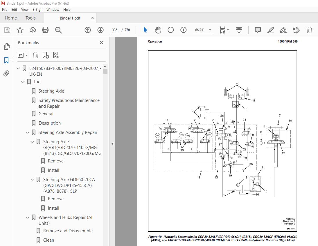
TABLE OF CONTENTS:
Yale Forklift B839 (ERC070-120HH) Service Manual – PDF DOWNLOAD
524150783-1600YRM0326-(03-2007)-UK-EN 1
toc 1
Steering Axle 1
Safety Precautions Maintenance and Repair 2
General 5
Description 5
Steering Axle Assembly Repair 10
Steering Axle GP/GLP/GDP070-110LG/MG (B813), GC/GLC070-120LG/MG 10
Remove 10
Install 10
Steering Axle GDP60-70CA (GP/GLP/GDP135-155CA) (A878, B878), GLP 11
Remove 11
Install 11
Wheels and Hubs Repair (All Units) 12
Remove and Disassemble 12
Clean 12
Inspect 12
Assemble and Install 12
Spindles and Bearings Repair (All Units) 14
Remove 14
Clean 14
Assemble and Install 15
Tie Rods Repair (All Units) 16
Remove 16
Clean 16
Install 16
Steering Cylinder Repair 19
Remove and Disassemble 19
Clean and Inspect 19
Assemble and Install 19
Troubleshooting 20
524150790-2100YRM0103-(03-2007)-UK-EN 25
toc 25
Tilt Cylinders 25
Safety Precautions Maintenance and Repair 26
General 29
Description 29
Tilt Cylinder Repair 29
Remove 29
Disassemble 29
Clean 29
Assemble 30
Tilt Cylinders With O-Ring or Single-Lip Seals 30
Tilt Cylinders 31
Install 32
Tilt Cylinder Leak Check 34
Tilt Cylinder Stroke and Mast Tilt Angle Adjustment 35
Torque Specifications 35
Piston Rod Nut 35
Retainer 35
Troubleshooting 36
tables 25
Table 1 Movement Rates (Maximum) for Tilt Cylinders 34
524150797-8000YRM0231-(02-2023)-UK-EN 41
General 47
Threaded Fasteners 47
Nomenclature, Threads 47
Strength Identification 48
Cotter (Split) Pins 49
Fastener Torque Tables 54
Conversion Table 56
524150797-8000YRM0231-(03-2020)-UK-EN 63
General 67
Threaded Fasteners 67
Nomenclature, Threads 67
Strength Identification 68
Cotter (Split) Pins 69
Fastener Torque Tables 74
Conversion Table 76
524153919-4000YRM0741-(03-2005)-UK-EN 83
toc 83
Lift Cylinders 83
Safety Precautions Maintenance and Repair 84
Safety Procedures When Working Near Mast 87
General 89
Description 89
Lowering Control Valve (Velocity Fuse) 89
Lift Cylinder Repair 92
Remove 92
Disassemble 93
Assemble 93
Install 93
Lift System Leak Check 94
Troubleshooting 95
524153920-4000YRM0736-(07-2010)-UK-EN 99
toc 99
Masts 99
Safety Precautions Maintenance and Repair 100
General 103
Description and Operation 103
Carriages 103
Two-Stage Mast With Limited Free-Lift 103
Two-Stage Mast With Full Free-Lift 104
Three-Stage Mast With Full Free-Lift 105
Safety Procedures When Working Near Mast 107
Fork Replacement 109
Remove 110
Install 110
Carriage Repair 111
Remove 111
Sideshift Carriage Repair 113
Remove 113
Disassemble 113
Assemble 113
Install 113
Two-Stage Mast With Limited Free-Lift Repair 115
Remove, GLP/GDP3 5-5 5LJ/MJ (GP/GLP/GDP070-120LJ/MJ) Model Lift 115
Remove, GC070-120LJ/MJ, ERC070-120HG (A839), and ERC35-55HG (ERC 117
Disassemble 120
Clean and Inspect 120
Assemble 121
Install, GLP/GDP3 5-5 5LJ/MJ (GP/GLP/GDP070-120LJ/MJ) Lift Truck 122
Install, GC070-120LJ/MJ, ERC070-120HG (A839), and ERC35-55HG (ER 124
Two-Stage Mast With Full Free-Lift Repair 126
Remove 126
Disassemble 126
Clean and Inspect 128
Assemble 128
Install 128
Three-Stage Mast With Full Free-Lift Repair 130
Remove 130
Disassemble 130
Clean and Inspect 134
Assemble 134
Install 135
Mast Operation Check 141
Lift and Tilt System Leak Check 142
Lift System 142
Tilt System 143
Tilt Cylinder Stroke and Backward Tilt Angle Adjustment 144
Lift Chain Adjustments 146
Mast Adjustments 148
Carriage Adjustment 150
Troubleshooting 151
tables 99
Table 1 Tilt Cylinder Leak Check Specifications, GC070-120LJ/MJ 143
Table 2 Hook-Type Carriage Chain Adjustment 146
Table 3 Pin-Type Carriage Chain Adjustment 147
524158040-2240YRM0001-(01-2023)-UK-EN 157
General 163
Battery Type 163
Lead-Acid Batteries 163
Lithium-Ion Batteries 164
Specific Gravity 164
Chemical Reaction in a Cell 164
Electrical Terms 166
Battery Selection 167
Battery Voltage 168
Battery as a Counterweight 168
Battery Ratings 168
Kilowatt-Hours 168
Battery Maintenance 169
Safety Procedures 169
Maintenance Records 169
New Battery 169
Cleaning Battery 170
Adding Water to Battery 172
Hydrometer 172
Battery Temperature 173
Charging Battery 174
Types of Battery Charges 175
Methods of Charging 176
Troubleshooting Charger 177
Knowing When Battery Is Fully Charged 177
Where to Charge Batteries 177
Equipment Needed 177
Battery Connectors 178
Battery Care 178
Troubleshooting 180
524158040-2240YRM0001-(03-2020)-UK-EN 185
General 189
Battery Type 189
Lead-Acid Batteries 189
Lithium-Ion Batteries 190
Specific Gravity 190
Chemical Reaction in a Cell 190
Electrical Terms 192
Battery Selection 192
Battery Voltage 193
Battery as a Counterweight 194
Battery Ratings 194
Kilowatt-Hours 194
Battery Maintenance 194
Safety Procedures 194
Maintenance Records 195
New Battery 195
Cleaning Battery 195
Adding Water to Battery 197
Hydrometer 198
Battery Temperature 199
Charging Battery 200
Types of Battery Charges 200
Methods of Charging 202
Troubleshooting Charger 202
Knowing When Battery Is Fully Charged 203
Where to Charge Batteries 203
Equipment Needed 203
Battery Connectors 204
Battery Care 204
Troubleshooting 206
524158753-1600YRM0720-(11-2006)-UK-EN 211
toc 211
Steering Housing and Control Unit 211
Safety Precautions Maintenance and Repair 212
General 215
Description 215
Operation 216
Steering Wheel and Column Assembly Repair 217
Assembly Components, Remove 217
Steering Control Unit, Disassemble 222
Steering Control Unit, Clean 222
Steering Control Unit, Assemble 222
Assembly Components, Install 224
System Air Removal 226
Troubleshooting 226
524166834-1400YRM0413-(11-2006)-UK-EN 231
toc 231
Drive Axle, Speed Reducer, and Differential 231
Safety Precautions Maintenance and Repair 232
General 235
Description 235
Drive Axle, Speed Reducer, and Differential Repair 236
Remove 236
General 236
Traction Motor, Speed Reducer, and Differential 237
Motor, Speed Reducer, and Differential, Remove 237
Disassemble 240
Speed Reducer 240
Differential 241
Clean 242
Inspect 242
Assemble 242
Speed Reducer 242
Input Gear, Install 242
New Pinion, Install 242
Differential 245
Drive Axle Housing 248
Remove 248
Clean 249
Inspect 249
Assemble 249
Troubleshooting 252
tables 231
Table 1 Pinion Assembly Shims Adjustment 244
Table 2 Ring and Pinion Tooth Contact Adjustment 246
524166837-1800YRM0338-(05-2009)-UK-EN 255
toc 255
Brake System 255
Safety Precautions Maintenance and Repair 256
General 259
Description and Operation 259
Brake Booster and Master Cylinder 259
Master Cylinder 259
Service Brake Assembly 259
Parking Brake 263
Seat Brake 264
Brake Shoe Assemblies Repair 265
Remove and Disassemble 265
Clean and Inspect 265
Assemble and Install 267
Master Cylinder Repair 271
Master Cylinder For Lift Truck Models GC/GLC70-120LG/MG (B818) a 271
Remove 271
Disassemble 271
Assemble 272
Install 272
Master Cylinder For Lift Truck Models ERC70-120HD, ERC70-120HG ( 273
Remove and Disassemble 273
Clean and Inspect 274
Assemble and Install 274
Brake Booster Repair 274
Remove 274
Disassemble 274
Clean and Inspect 275
Assemble 276
Install 276
Brake System Air Removal 276
Brake Pedal Adjustment 276
Brake Pedal GP/GLP/GDP70-120LG/MG (B813) With Manual Transmissio 276
Brake Shoes Adjustment 278
Parking Brake Adjustment 278
Parking Brake Adjustment, Lift Truck Models GC/GLC70-120LG/MG (B 278
Parking Brake Lever and Switch Adjustment ERC70-120HD and ERC70- 279
Seat Brake Assembly 280
Remove 280
Clean and Inspect 280
Install 280
Adjustments 282
Solenoid Adjustment 282
Traction cutoff Switch Adjustment 282
Cable Adjustment 282
Brake Booster Relief Valve Check 285
Troubleshooting 285
524166839-2000YRM0077-(02-2009)-UK-EN 291
toc 291
Manual hydraulic Control Valve 291
Safety Precautions Maintenance and Repair 292
General 295
Description 295
Operation 297
Lift Section 299
Tilt Section 300
Tilt Backward 300
Tilt Forward 300
Relief Valve 302
Solenoid Valve for Auxiliary Function 303
Main Control Valve Repair 304
Remove and Disassemble – Control Valve Without OPS Solenoid 304
Remove and Disassemble – Control Valve With OPS Solenoid 304
Clean and Inspect 306
Assemble – Control Valve Without OPS 306
Assemble – Control Valve With OPS 306
Install 307
Solenoid Valve for Auxiliary Function Repair 307
Remove and Disassemble 307
Assemble and Install 309
Troubleshooting 309
Pressure Relief Valve Check and Adjustment 310
Primary Relief Valve 310
Secondary Relief Valve 310
Control Lever Arrangement and Adjustment 311
Specifications 313
Troubleshooting 313
524179945-1900YRM0559-(04-2009)-UK-EN 319
toc 319
Hydraulic System 319
Safety Precautions Maintenance and Repair 320
General 323
Description 323
Hydraulic System 323
Operation 331
Hydraulic System 331
Hydraulic Gear Pump 337
Steering Pump 337
Hydraulic Tank Repair 345
Tank, Remove [ERC/P16-20AAF (ERC030-040AF, AG/BG) (A814); ERC/P1 345
Tank, Remove [ERP20-30ALF (B216) and ERP20-30ALF (ERP040-060DH) 347
Tank, Remove [ERP20-32ALF (ERP040-065DH) (E216)] 348
Hydraulic Tank [ERC35-55HG (ERC70-120HH) (B839/C839)] 348
Inspect 349
Small Leaks, Repair 350
Large Leaks, Repair 350
Clean 350
Steam Method 350
Chemical Solution Method 351
Additional Methods for Tank Repair 351
Tank, Install [ERC/P16-20AAF (ERC030-040AF, AG/BG) (A814); ERC/P 351
Tank, Install [ERP20-30ALF (B216) and ERP20-30ALF (ERP040-060DH) 352
Tank, Install [ERP20-32ALF (ERP040-065DH) (E216)] 352
Filter Replacement 353
All Lift Trucks Except [ERC35-55HG (ERC70-120HH) (B839/C839); ER 353
Remove 353
Install 354
Lift Truck Models [ERC35-55HG (ERC70-120HH) (B839/C839)] 354
Remove 354
Install 354
Lift truck Models [ERC20-32AGF (ERC040-065GH) (A908) and ERC/P16 355
Remove 355
Install 355
Lift Truck Models [ERP20-32ALF (ERP040-065DH) (E216)] 357
Remove 357
Install 357
Hydraulic Pump Repair 360
Hydraulic Pump, Remove [ERC/P16-20AAF (ERC030-040AF, AG/BG) (A81 360
Hydraulic Pump, Disassemble ERC/P16-20AAF (ERC030-040AF, AG/BG) 360
Inspect 362
Clean 362
Pump Seal Replace and Pump Assemble 362
Assemble Pump on Motor 362
Hydraulic Pump and Motor, Install [ERC/P16-20AAF (ERC030-040AF, 364
Hydraulic Pump, Remove [ERP20-30ALF (B216); ERP20-30ALF (ERP040- 365
Hydraulic Pump, Disassemble [ERC35-55HG (ERC70-120HH) (B839/C839 366
Hydraulic Pump, Inspect [ERC35-55HG (ERC70-120HH) (B839/C839) an 368
Hydraulic Pump, Clean [ERC35-55HG (ERC70-120HH) (B839/C839) and 368
Hydraulic Pump, Assemble [ERC35-55HG (ERC70-120HH) (B839/C839) a 368
Hydraulic Pump and Motor, Install [ERP20-30ALF (B216); ERP20-30A 368
Main Control Valve Repair 370
Steering Pump Repair 370
Pump, Remove and Disassemble [ERC/P16-20AAF (ERC030-040AF, ERC03 370
Pump, Remove and Disassemble [ERP20-30ALF (B216); ERP20-30ALF (E 372
Pump, Assemble and Install 374
Steering Control Unit Replacement 375
Remove 375
Install 375
Steering Cylinder Repair 381
Main Control Valve Check and Adjust 381
Steering Relief Valve Check and Adjust 382
Specifications 382
Relief Valve Pressures* 382
Hydraulic Tank Capacity (dipstick full mark) 383
Hydraulic Pump Capacities – All Models Except ERC35-55HG (ERC70- 383
Hydraulic Pump Capacities – Models ERC35-55HG (ERC70-120HH) (B83 383
Troubleshooting 383
Steering 383
Steering Housing and Steering Control Unit 384
Hydraulic System 385
524183081-1600YRM1054-(11-2006)-UK-EN 391
toc 391
Steering System for AC Electric Lift Trucks 391
Safety Precautions Maintenance and Repair 392
General 395
Description 396
Steering Wheel and Column Assembly Repair 397
General 397
Assembly Components, Remove 399
Assembly Components, Install 400
Power Steering Motor and Pump 401
Description 401
Remove 401
Disassemble 404
Install 404
Power Steering Pump, Repair 404
Seal, Replace 405
Steering System Air Removal 406
Steering Pressure Check 406
Steering Motor Circuits Check 407
Troubleshooting 408
524183082-2200YRM1055-(10-2009)-UK-EN 413
toc 413
Electrical System (Trucks With AC Controllers) 413
Safety Precautions Maintenance and Repair 414
General 417
Description 418
Features of the Display Panels 418
Other Control Components 419
Display Panel and Key Switch Replacement 420
Display Panel, Replace 420
Key Switch, Replace 422
Controller Replacement 422
Traction and Pump Motor Controller Replacement 422
Master Controller, Replace 428
Master Controller, Remove ERP20-30ALF (ERP040-060DH) (D216), ERP 428
Master Controller, Install ERP20-30ALF (ERP040-060DH) (D216), ER 428
Master Controller, Remove ERC/P16-20AAF (ERC030-040AH) (B814/C81 430
Master Controller, Install ERC/P16-20AAF (ERC030-040AH) (B814/C8 430
Master Controller, Remove ERC35-55HG (ERC070-120HH) (B839/C839) 432
Master Controller, Install ERC35-55HG (ERC070-120HH) (B839/C839) 432
Control Components Replacement 433
General 433
Start Switch, Replace 433
Brake Light Switch, Replace 434
Seat Switch, Replace 434
Parking Brake Switch, Replace 435
Foot Directional Control Pedal Direction Switches, Replace 437
Steering Column Direction Control Switches, Replace 440
Remove 440
Install 440
Brake Fluid Switch, Replace 442
Brush Wear and Over Temperature Sensors (DC Pump Motor Only) 442
Rocker Switches for Lights, Replace 442
Accelerator Position Sensor, Replace 443
On-Demand Steering Sensor, Replace 444
Lights, Converter, Relay, and Reverse Alarm 444
Brake, Tail, and Reverse Light Assembly, Replace 445
Incandescent Assembly 445
LED Assembly – Remove 447
LED Assembly – Install 447
Strobe Light Assembly, Replace 450
Wire Harness Repair 451
Del-City Crimp-Solder-Shrink Splice 451
Front, Rear Driving Light or Spot Light Assemblies, Replace 452
Converter, Replace 452
Remove, Lift Truck Models ERP20-30ALF (ERP040-060DH) (D216), ERP 452
Install, Lift Truck Models ERP20-30ALF (ERP040-060DH) (D216), ER 454
Remove, Lift Truck Models ERC20-32AGF (ERC040-065GH) (A908) and 454
Install, Lift Truck Models ERC20-32AGF (ERC040-065GH) (A908) and 454
Remove, Lift Truck Models ERC35-55HG (ERC70-120HH) (B839/C839) 456
Install, Lift Truck Models ERC35-55HG (ERC70-120HH) (B839/C839) 456
Reverse Relay, Replace 457
Lift Truck Models ERC20-32AGF (ERC040-065GH) (A908), ERC/P16-20A 457
Lift Truck Models ERC35-55HG (ERC70-120HH) (B839/C839) 457
Backup Alarm, Replace 459
Horn and Horn Button, Replace 459
Horn Replacement for Lift Trucks ERP20-30ALF (ERP040-060DH) (D21 459
Horn Replacement for Lift Trucks ERC35-55HG (ERC70-120HH) (B839/ 461
Horn Switch and Cover, Replace 462
Hydraulic Pump Switches 463
Fan Power Supply, Replace 463
Remove, Lift Truck Models ERC35-55HG (ERC70-120HH) (B839/C839) 463
Install, Lift Truck Models ERC35-55HG (ERC70-120HH) (B839/C839) 463
Remove, Lift Truck Models ERP20-30ALF (ERP040-060DH) (D216) and 464
Install, Lift Truck Models ERP20-30ALF (ERP040-060DH) (D216) and 465
Remove, Lift Truck Models ERC20-32AGF (ERC040-065GH) (A908) 465
Install, Lift Truck Models ERC20-32AGF (ERC040-065GH) (A908) 465
Control and Power Fuse Check 466
Fuse Locations 466
Brake Light Switch Adjustment 472
Seat Switch Check 473
Seat Brake Adjustment 473
Parking Brake Switch Adjustment 474
Direction Switches Check 474
Foot Directional Control Pedal 474
Steering Column 475
Foot Directional Control Pedal or Accelerator Pedal Adjustment 475
Accelerator Position Sensor Adjustment and Start Switch Adjustme 476
Acceleration Position Sensor, Adjust 476
Start Switch, Adjust 478
tables 413
Table 1 Wire Splice Size 451
524183083-2200YRM1056-(03-2009)-UK-EN 481
toc 481
AC Motor Controllers/Display Panel 481
Safety Precautions Maintenance and Repair 482
Description 485
General 485
AC Motors 485
Motor Controllers 485
Master Controller 485
Dash Display 485
Controller Area Network Bus (CANbus) 485
Master Controller Checks and Adjustments 486
Function Settings 487
General 487
Function Numbers 487
Function Descriptions 490
General 490
Function Number 1 BATTERY VOLTAGE 490
Function Number 2 EXTENDED SHIFT 490
Function Number 3 ACCELERATION 1 490
Function Number 4 ACCELERATION 2 490
Function Number 5 TOP SPEED LIMIT 490
Function Number 6 REGEN BRAKING 490
Function Number 7 AUTO DECELERATION 491
Function Number 8 BDI ADJUSTMENT 491
Function Number 9 LIFT INTERRUPT 491
Function Number 10 POWER STEERING TIME DELAY 491
Function Number 11 SERVICE REMINDER 491
Function Number 12 CUSTOM 491
Function Number 13 PUMP SPEED 1 491
Function Number 14 PUMP SPEED 2 492
Function Number 15 PUMP SPEED 3 492
Function Number 16 PUMP ACCELERATION 492
Troubleshooting 492
General 492
Controller Status Light Emitting Diodes (LEDs) 493
Master Controller 493
AC Motor Controllers 493
Status Codes 499
AC Motor Controllers Status Code Charts 501
Troubleshooting When Dash and/or Lift Truck is not Operational 522
Typical Symptoms 522
Truck Runs but Dash Display is not Operational, or Only Displays 522
Truck Does Not Run and Dash is Not Operational or Only Displays 523
Hydraulics Operate Normally, Traction Does Not Operate Correctly 524
Traction Operates Normally, Hydraulics do Not Operate Correctly, 524
AC Transistor Motor Controller Replacement 524
General 524
General Maintenance Instructions 530
Special Precautions 530
Fuses 531
Fan Test 531
Contactors 531
Repair 531
Thermal Sensors 535
Motor Controller, Replace 535
Display Panel 536
General 536
Premium Display Panel 536
Standard Display Panel 536
Display Functions and Features 537
Key-On Initialization 537
Standard Display 538
Premium Display 538
Lift Truck Inspection Function 539
Access to Service Functions 539
Service Functions 539
Service Functions 540
Performance Modes 542
Battery Discharge Indicator (BDI) 542
Hourmeter 543
Dash Display Service Menu Navigation 549
General 549
Moving Through Menu Selections 549
Editing and Adding Information 549
tables 481
Table 1 Factory Parameters for ERP20-30ALF (ERP040-060DH) (D216 487
Table 2 Factory Setting for ERC020-032AGF (ERC40-65GH) (A908) 488
Table 3 Factory Setting for ERC/P16-20AAF (ERC030-040AH) (B814/ 488
Table 4 Factory Parameters for ERC35-55HG (ERC70-120HH) (B839/C 489
Table 5 List of Status Codes 499
Table 6 42-Pin Connections/Descriptions for Master Controller 532
Table 7 Pin Connections/Descriptions for 72/80 (Gen IV) Volt Mo 534
Table 8 Pin Connections/Descriptions for 36/48 and 72v/80v (Gen 534
524183085-2200YRM1058-(04-2011)-UK-EN 553
toc 553
Troubleshooting and Adjustments Using the AC Controls Program (E 553
Safety Precautions Maintenance and Repair 554
General 557
Computer Requirements 557
Software, Install 557
Language Selection 557
Demo Mode 558
Connect PC to Lift Truck 562
Starting AC Controls Program 564
Lift Truck Control Setup 569
Change Lift Truck Serial Number or Hourmeter 569
Setting Factory Default Values or Changing Lift Truck Parameters 570
Create New Custom Lift Truck Configuration 576
Lift Truck Configuration Properties 579
Import New Lift Truck Configuration From Disk 582
Delete Custom Lift Truck Configuration or Password File 584
Dash Display 587
Custom Display Languages 587
Download Display Language 589
Clear Operator Log 589
Password Functions 592
Enable/Disable Password and Lift Truck Inspection Functions 592
Truck Inspection Checklist 592
Password 592
Password Properties 592
Create New Password File 597
Download Passwords 598
Upload Passwords 600
Reports Menu 602
Devices Report 602
Custom Report 602
Password Report 602
Operator Report 609
Current Settings Report 612
Status Code Report 616
Status Codes Log 619
Troubleshooting 621
Diagnostics 621
Help Menu 624
General 624
Contents 624
Technical Support 624
About Electric Truck AC Controls Program 624
524205680-0620YRM1098-(03-2010)-UK-EN 631
toc 631
AC Motor Repair 631
Safety Precautions Maintenance and Repair 632
General 635
AC Motor Repair 635
Disassemble 635
Assemble 639
Troubleshooting 641
524238572-0100YRM1200-(11-2006)-UK-EN 645
toc 645
Frame 645
Safety Precautions Maintenance and Repair 646
General 649
Description 649
Overhead Guard Replacement 651
Remove 651
Install 652
Battery and Operator Restraint, Hood and Seat Brake Repair 653
Battery Restraint and Hood Repair 653
Operator Restraint System and Seat Assembly 656
Automatic Locking Retractor (ALR) 656
Emergency Locking Retractor (ELR) 656
Seat Brake Repair 657
Counterweight Replacement 657
Remove 657
Install 658
Traction Motor Repair 658
Remove 658
Install 659
Hydraulic Tank Repair 660
Inspect 660
Small Leaks, Repair 660
Large Leaks, Repair 660
Clean 660
Steam Method 661
Chemical Solution Method 661
Additional Preparations For Repair 661
Safety Label Replacement 662
Battery Specifications 664
tables 645
Table 1 Torque Values 652
Table 2 Weight of Counterweights 657
Table 3 Battery Specifications* 664
524238574-8000YRM1201-(02-2010)-UK-EN 667
toc 667
Periodic Maintenance 667
Safety Precautions Maintenance and Repair 668
General 673
How to Move Disabled Lift Truck 673
How to Tow Lift Truck 673
How to Put Lift Trucks on Blocks 674
How to Raise Drive Tires 674
How to Raise Steering Tires 674
How to Clean a Lift Truck 675
Maintenance Schedule 676
Maintenance Procedures Every 8 Hours or Daily 680
General 680
How to Make Checks With Key Switch OFF 681
Tires and Wheels 681
Forks 681
Remove 681
Inspect 681
Install 682
Adjust 682
Inspection of Mast, Mast Pivots, Header Hoses and Lift Chains 683
Safety Labels 683
Steering Column Latch 683
Operator Restraint System 684
Automatic Locking Retractor (ALR) 684
Emergency Locking Retractor (ELR) 684
Battery Restraint System 685
Battery 686
Hydraulic System 687
How to Make Checks With Key Switch ON 688
Horn, Lights, and Alarm 688
Steering System 689
Service Brakes 689
Parking Brake 689
Seat Brake 689
Control Levers and Pedals 689
Direction and Speed Control Pedals 689
Lift System Operation 689
Oil Leaks 690
First Service After First 100 Hours of Operation 690
Change Hydraulic Oil and Filter 690
Lift Truck Models ERC35-55HG (ERC70-120HH) (C839) 690
Remove 690
Install 692
Lift Truck Models ERC35-55HG (ERC70-120HH) (B839) 693
Remove 693
Install 694
Maintenance Procedures Every 500 Hours or 3 Months 695
Wheel Nuts 695
Header Hose Checks 695
Mast Lubrication 695
Integral Sideshift Carriage 698
Brake Fluid 699
Other Lubrication 699
Maintenance Procedures Every 1000 Hours or 6 Months 699
Differential and Speed Reducer 699
Lift Chains 699
Wear Check 699
Lubrication 700
Forks 700
Parking Brake 700
Brake Linkage Shafts 701
Steering Spindles and Tie Rod Ends 701
Seat Rails 701
Seat Plate Hinges 701
Electrical Inspection 702
Contactors 702
Maintenance Procedures Every 2000 Hours or Yearly 704
Brake Fluid 704
Hydraulic System 705
Hydraulic Tank Breather, Lift Truck Models ERC35-55HG (ERC70-120 705
Change Hydraulic Oil and Hydraulic Oil Filter, Lift Truck Models 705
Remove 705
Install 706
Hydraulic Tank Breather, Lift Truck Models ERC35-55HG (ERC70-120 707
Remove 707
Install 707
Change Hydraulic Oil and Hydraulic Oil Filter, Lift Truck Models 707
Remove 707
Install 709
Differential and Speed Reducer 709
Service Brakes 710
Wheel Bearings 710
Steer Wheels, Lubrication 710
Drive Wheels, Lubrication 710
Lift Chains 710
Battery Maintenance 711
How to Charge Battery 711
How to Change Battery 712
Safety Procedures When Working Near Mast 715
Lift and Tilt System Leak Check 718
Check Lift Cylinders for Leaks 718
Check Tilt Cylinders for Leaks 718
Lift Chain Adjustments 719
Welding Repairs 720
Overhead Guard Changes 721
Wheels and Tires 721
General 721
Remove Wheels From Lift Truck 721
Remove Tire From Wheel and Install Tire on Wheel 721
Remove 721
Install 721
Install Wheels 722
tables 667
Table 1 Maintenance Schedule 677
Table 2 Battery Specifications* 715
Table 3 Hook-Type Carriage Chain Adjustment 720
524238575-8000YRM1202-(11-2006)-UK-EN 725
toc 725
Capacities and Specifications 725
Safety Precautions Maintenance and Repair 726
Lift Truck Lifting Capacity 729
Counterweight Weights 729
Tire Sizes 729
Capacities 730
Hydraulic System 730
Steering System 731
Specifications 731
Turning Radius 731
Mast Speeds 732
Maximum Carriage and Tilt Creep Rates 733
Battery Specifications 733
Traction Motor Speed 734
Battery Current at Hoist Relief 734
Torque Specifications 734
Brake System 734
Differential 735
Drive Axle 735
Frame 735
Mast 735
Main Control Valve 735
Steering System 735
Tilt Cylinders 736
Hydraulic System 736
Electrical System 736
tables 725
Table 1 Manual Control Valve 730
Table 2 E-Hydraulic Control Valve 730
524238576-8000YRM1203-(02-2009)-UK-EN 739
toc 739
Diagrams 739
Safety Precautions Maintenance and Repair 740
More products