$41.95
Yale Forklift B877 (GDP300-360EB) Service Manual – PDF DOWNLOAD
Yale Forklift B877 (GDP300-360EB) Service Manual – PDF DOWNLOAD
FILE DETAILS:
Yale Forklift B877 (GDP300-360EB) Service Manual – PDF DOWNLOAD
Language : English
Pages : 1758
Downloadable : Yes
File Type : PDF
IMAGES PREVIEW OF THE MANUAL:
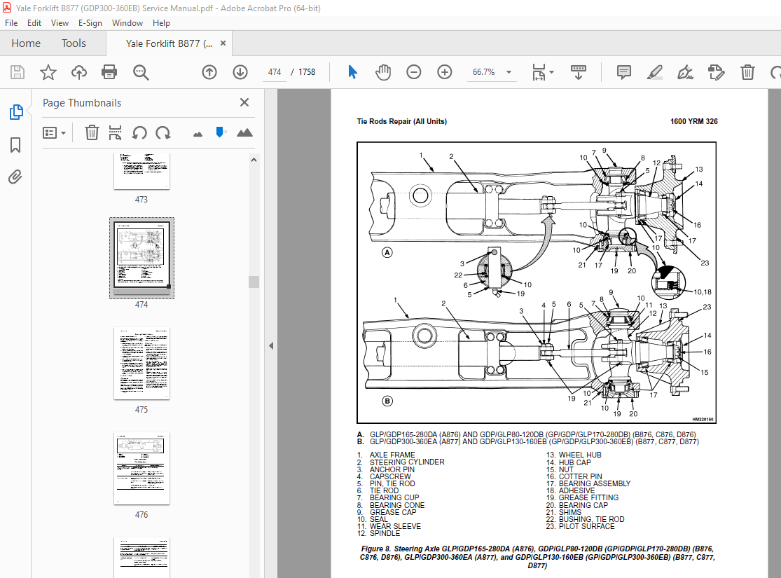
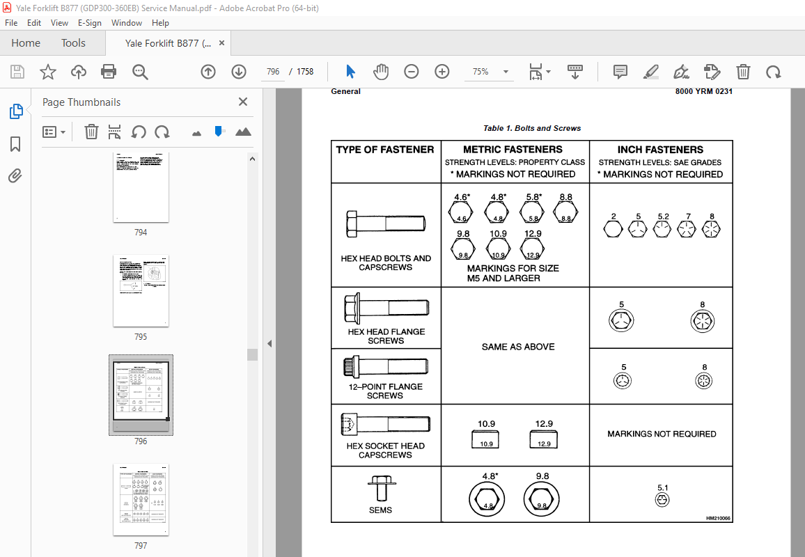
TABLE OF CONTENTS:
Yale Forklift B877 (GDP300-360EB) Service Manual – PDF DOWNLOAD
524149351 8000YRM0934 (04 2003) US EN 1
toc 1
Periodic Maintenance 1
Safety Precautions Maintenance and Repair 2
General 5
How to Move Disabled Lift Truck 5
How to Tow Lift Truck 5
How to Put Lift Truck on Blocks 6
How to Raise Drive Tires 6
How to Raise Steering Tires 6
Maintenance Schedule 7
Maintenance Procedures Every 8 Hours or Daily 14
How to Make Checks With Engine Stopped 14
Tires and Wheels 14
Forks 14
Adjust 14
Remove 15
Install 15
Forks, Mast, and Lift Chains, Inspect 15
Safety Labels 16
Operator Restraint System 16
Steering Column Latch 16
Drive Belts 16
Cooling System 17
Fuel, Oil, or Coolant Leaks, Check 18
Cab Hydraulic System 18
Hydraulic System 18
Engine Oil 19
Fuel System 20
Primary Fuel Filter 20
Battery 20
Air Filter 20
How to Make Checks With Engine Running 20
Gauges, Lights, Horn, and Fuses 20
Control Levers and Pedals 21
Transmission Oil 21
Lift System Operation 21
Brakes 21
Steering System 23
Maintenance Procedures Every 250 Hours or Every 2 Months 23
Engine Oil and Filter – Cummins Engine 23
Maintenance Procedures Every 500 Hours or Every 2 Months 24
Lift Chains 24
Lubrication 24
Adjust 24
Drive Shaft 24
Steering Axle 24
Wheel Nuts 25
Shafts for Brake Actuators 25
Drive Axle and Differential 25
Hydraulic Tank Breather 25
Air Filter, Engine, and Air Compressor 25
Cabin Air Filter, Heater 25
Engine Oil and Filter – Perkins Engine 25
Drive Belts 26
Mast 26
General Lubrication 27
Fork Wear and Damage Check 27
Lift Chains Wear Check 27
Fuel System 28
Idle Speed 28
Governor Speed (Diesel) 28
Maintenance Procedures Every 1000 Hours or 6 Months 29
Transmission Oil and Filter, Change 29
Final Fuel Filters, Diesel 29
Diesel Fuel System Air Removal 29
Fuel Injection Pump Without Vent Tube 30
Fuel Injection Pump Timing 31
Valve Adjustment 31
Maintenance Procedures Every 2000 Hours or Yearly 32
Hydraulic System 32
Hydraulic Oil Filter, Change 32
Hydraulic Oil, Change 32
Differential and Drive Axle 32
Wheel Bearings 32
Steer Wheels 32
Drive Wheels 32
Service Brakes 33
Cleaning Procedures (Dry Brake Axle) 33
Safety Procedures When Working Near Mast 33
Fuel Injectors Check 34
Lift and Tilt System Leak Check 35
Lift System 35
Tilt System 35
Welding Repairs 36
Wheel and Tire Replacement 36
Remove Wheels From Lift Truck 36
Pneumatic Tires 37
Remove Tire From Wheel 37
Remove Tire From Three- and Four-Piece Wheel 37
Install Tire on Wheel 38
Install Three- or Four-Piece Wheel in Tire 39
Add Air to Tires 40
Solid Rubber Tires 40
Remove Tire From Wheel 40
Install Tire on Wheel 42
Wheels, Install 44
tables 1
Table 1 Maintenance Schedule 8
Table 2 Allowable Mast Movement from Internal Leakage 35
524150772 0100YRM0927 (11 2015) US EN 47
General 51
Description 51
Counterweight Repair 52
Remove 52
Install 54
Fenders 54
Remove 54
Install 54
Side Counterweights GDP130-160EB (GP300-360EB) 54
Side Counterweight, Replace 54
Hood and Air Cleaner Repair 54
Remove 55
Install 57
Hydraulic Tank Repair 57
Remove 57
Repairs, All Units 60
Small Leaks 60
Large Leaks 60
Clean 60
Steam Method 61
Chemical Solution Method 61
Other Methods of Preparation for Repair 61
Install 62
Fuel Tank Repair 62
Remove 62
Repairs 63
Install 63
Cooling System and Radiator Repair 66
Remove 66
Install 66
Cab Repair 69
Rear Cab Assembly 69
Bottom Cab Assembly 70
Raising and Lowering Cab 70
Raise Cab 70
Lower Cab 71
Cab Repair 71
Remove 71
Install 73
Engine and Transmission Repair 74
Transmission, Remove 74
Transmission, Install 76
TE-10 Transmission 77
Remove 77
Install 81
Label Replacement 85
524150774 0600YRM0705 (03 2006) US EN 93
toc 93
Perkins Diesel Engines 93
Safety Precautions Maintenance and Repair 94
General 101
General Safety Rules 101
Description 102
Engine Serial Number Codes 105
Engine Data 105
Engine Removal and Installation 107
Lift Engine 107
Cylinder Head Assembly Repair 107
Valve Cover 107
Remove 107
Install 108
Rocker Arm Assembly 108
Remove 108
Install 108
Disassemble 108
Inspect 109
Assemble 109
Valve Clearance Adjustments 109
Four-Cylinder Engines 110
Six-Cylinder Engines 110
Valve Springs 110
Cylinder Head Assembly 112
Remove 112
Install 114
Valves and Valve Springs 118
Remove 118
Inspect 118
Install 119
Valve Guides 119
Inspect 119
Remove 120
Install 120
Cylinder Head and Valve Seats 120
Inspect 120
Repair 120
New Valve Seats, Install 120
Piston and Connecting Rod Assemblies Repair 122
Rod Bearings 122
Remove 123
Install 123
Piston and Connecting Rod Assembly 124
Service Note 124
Remove 124
Install 125
Piston Rings 126
Remove 126
Inspect 126
Install 126
Piston and Connecting Rod 127
Disassemble 127
Inspect 128
How to Select Correct Replacements 128
Install 129
Piston Cooling Jets 129
Remove 129
Install 130
Crankshaft Assembly Repair 130
General 130
Crankshaft Pulley 131
Engine AR, Remove 131
Engines YG and YH, Remove 131
Inspect 132
Engine AR, Install 132
Engines YG and YH, Install 132
Rear Oil Seal 133
Replace 133
Main Bearings 134
Remove 134
Inspect 135
Install 135
Thrust Washers 135
Crankshaft Axial Movement, Check 135
Remove 136
Install 136
Crankshaft 137
Remove 137
Inspect 137
Install 137
Flywheel 139
Remove 139
Ring Gear, Replace 139
Install 139
Flywheel Housing 140
Remove 140
Install 140
Timing Case and Timing Gears Repair 141
General 141
Timing Case Cover 141
Remove 141
Install 142
Front Oil Seal 142
Remove 142
Install 142
Crankshaft Pulley Wear Sleeve 143
Install 143
Idler Gear and Hub 143
Remove 143
Install 144
Air Compressor Drive, Bendix 145
Disassemble 145
Assemble 146
Fuel Injection Pump Gear 146
Remove 147
Install 147
Camshaft Gear 148
Remove 148
Install 148
Crankshaft Gear 149
Remove 149
Install 149
Timing Case 149
Remove 149
Install 150
Camshaft and Tappets 151
Remove 151
Install 151
Cylinder Block Assembly Repair 152
Description 152
Cylinder Block 152
Disassemble 152
Inspect 153
Assemble 153
Cylinder Bore (Four-Cylinder Engines) 153
Cylinder Liner (Six-Cylinder Engines) 154
Inspect 154
Cylinder Liner Condition, Check 154
Remove 155
Service Liner, Install 155
Partially Finished Liner, Install 157
Engine Timing 157
Description 157
How to Set Number One Piston to TDC on Compression Stroke 159
How to Set Number One Piston to TDC on Compression Stroke (Alter 159
Valve Timing, Check 160
Fuel Injection Pump Timing, Check 161
Turbocharger – Engine YH Repair 162
General 162
Remove 162
Install 162
Impeller and Compressor Housing, Clean 163
Lubrication System Repair 164
General 164
Oil Filter, Replace 164
Filter Head 164
Remove and Install 164
Oil Sump 165
Remove 165
Install 165
Oil Pump 165
Remove 165
Inspect 166
Install 167
Relief Valve 167
Remove 167
Disassemble 168
Inspect 168
Assemble 168
Install 168
Idler Gear Shaft, Replace 169
Remove 169
Remove (Alternative) 169
Install 170
Install (Alternative) 170
Install (Alternative for Four-Cylinder Engines Only) 171
Fuel System Repair 171
Description 171
Fuel Injection Pump 172
Remove 172
Install 173
Check and Adjust 173
Fuel System Air Removal 174
Fuel Filter, Replace 175
Canister Type 175
Quick Release Canister Type 176
Fuel Injectors 177
Remove 177
Inspect 177
Install 177
Fuel Pump 178
Remove 178
Disassemble 178
Assemble 179
Install 180
Test 180
Cooling System Repair 180
General 180
Thermostat 180
Remove 180
Install 181
Test 181
Coolant Pump 181
Remove 181
Disassemble 182
Assemble 183
Install 186
Fan and Fan Drive 186
Remove 186
Install 187
Oil Cooler (Six-Cylinder Engines) 187
Remove 187
Disassemble and Assemble 187
Install 188
Oil Cooler Bypass Valve 188
Electrical Equipment Repair 188
Drive Belts 188
Adjustment 188
Remove 189
Install 189
Alternator 189
Remove 189
Install 189
Starter Motor 190
Remove 190
Install 190
Cold Start Aid 190
Air Compressor – Engines YG and YH 190
General 190
Repair 190
Remove 190
Install 191
Rotary Exhauster Replacement 192
Remove 192
Clean 192
Install 192
Engine Specifications 193
Cylinder Head Assembly 193
Piston and Connecting Rods 196
Crankshaft Assembly 199
Crankshaft Overhaul 200
Timing Case and Drive Assembly 202
Engine Block Assembly 203
Turbocharger 206
Lubrication System 206
Fuel System 207
Cooling System 209
Flywheel and Housing 209
Electrical Equipment 210
Torque Specifications 210
Cylinder Head Assembly 210
Piston and Connecting Rod Assemblies 210
Crankshaft Assembly 210
Timing Case and Drive Assembly 211
Turbocharger 211
Lubrication System 211
Fuel System 211
Cooling System 211
Flywheel 211
Auxiliary Equipment 211
Special Torque Specifications 212
Flywheel and Housing 212
Turbocharger 212
Electrical Equipment 212
Auxiliary Equipment 212
Special Tools* 213
Troubleshooting 218
tables 93
Table 1 Cylinder Head 193
Table 2 Valve Guides 193
Table 3 Inlet Valves 193
Table 4 Exhaust Valves 194
Table 5 Valve Springs 196
Table 6 Tappets 196
Table 7 Rocker Arm Shaft 196
Table 8 Rocker Arms and Bushings 196
Table 9 Pistons (Engine AR) 196
Table 10 Pistons (Engines YG and YH) 196
Table 11 Piston Rings (Engine AR) 197
Table 12 Piston Rings (Engines YG and YH) 197
Table 13 Piston Pins 198
Table 14 Connecting Rods 198
Table 15 Small End Bushings 198
Table 16 Connecting Rod Bearings (Engines AR and YG) 198
Table 17 Connecting Rod Bearings (Engine YH) 198
Table 18 Piston Cooling Jets 199
Table 19 Crankshaft 199
Table 20 Main Bearings 199
Table 21 Crankshaft Thrust Washers 199
Table 22 Crankshaft Heat Treatment 200
Table 23 Crankshaft Overhaul Specifications 200
Table 24 Maximum Variation (Run-out) 202
Table 25 Camshaft 202
Table 26 Camshaft Thrust Washer 202
Table 27 Camshaft Gear 202
Table 28 Gear for Fuel Injection Pump 203
Table 29 Crankshaft Gear 203
Table 30 Idler Gear and Hub 203
Table 31 Cylinder Block (Engine AR) 203
Table 32 Cylinder Bore Specifications 204
Table 33 Cylinder Block (Engines YG and YH) 205
Table 34 Cylinder Liners (Engines YG and YH) 205
Table 35 Cylinder Liner Specifications (Partially Finished) 205
Table 36 Oil Pump (Engine AR) 206
Table 37 Oil Pump (Engines YG and YH) 206
Table 38 Idler Gear for Oil Pump 206
Table 39 Relief Valve 207
Table 40 Oil Filter 207
Table 41 Lucas Fuel Injection Pump 207
Table 42 Fuel Injector Codes 208
Table 43 Fuel Pump (Engine AR) 209
Table 44 Fuel Pump (Engines YG and YH) 209
Table 45 Fuel Filter 209
Table 46 Coolant Pump 209
Table 47 Thermostat 209
Table 48 Fan Drive Housing 209
Table 49 Limits for Flywheel Run Out and Alignment (Total Indic 209
Table 50 Alternator 210
Table 51 Starter Motor 210
Table 52 Cold Start Aid 210
Table 53 List of Possible Causes 218
524150775 0700YRM0626 (03 2003) US EN 223
toc 223
Cooling System 223
Safety Precautions Maintenance and Repair 224
General 227
Description 228
Radiator 228
Radiator Cap 228
Thermostat 228
Water Pump 229
Fan and Fan Shroud 229
Cooling System Checks 229
Radiator 229
Thermostat 229
Water Pump 230
Exhaust Leaks 230
Fan and Fan Shroud 230
Radiator Cleaning 230
Drain 230
Clean 230
Fill 231
Troubleshooting 232
524150776 1300YRM0930 (08 2001) US EN 235
toc 235
Three-Speed Powershift Transmission 235
Safety Precautions Maintenance and Repair 236
General 239
Mechanical Description 239
General 239
Torque Converter 239
Description 239
Operation 239
Clutch Assemblies 243
Description 243
Operation 244
Forward and First-Speed Clutch Assembly 244
Reverse and Second-Speed Shaft, First and Second Gear Shaft 245
Third-Speed Shaft 245
Output Shaft 245
Hydraulic Operation 247
Sump, Filter and Pump 247
Transmission Control Valve 247
Solenoid Valves 247
Inching Spool 248
Direction Spools 248
Range Spool 248
Modulator Valve 249
Operation 249
Modulator Operation 250
Transmission Control System 253
Foot Directional Control Pedal 253
Control Lever 254
Hydraulic Circuits 255
Cooling and Lubrication 255
Neutral 255
Forward-First 255
Reverse-First 258
From First to Second Speed 259
From Second to Third Speed 260
Inching 261
524150777 1300YRM0931 (08 2001) US EN 265
toc 265
Three-Speed Powershift Transmission 265
Safety Precautions Maintenance and Repair 266
General 269
Transmission Repair 272
Remove 272
Disassemble 274
Torque Converter Housing and Pump Gears 274
Transmission Cover, Remove 275
Clutch Assemblies, Remove 277
Forward and Low-Speed Clutches 278
Forward Clutch, Disassemble 278
First-Speed Clutch, Disassemble 280
Reverse and Second-Speed Clutches, Disassemble 280
Second-Speed Clutch, Disassemble 280
Reverse Clutch, Disassemble 282
Third-Speed Clutch, Disassemble 282
Output Gears, Disassemble 284
Clean 284
Inspect 284
Assemble 286
Output Gears, Assemble 286
Third-Speed Clutch, Assemble 286
Reverse and Second-Speed Clutches, Assemble 286
Second-Speed Clutch, Assemble 286
Reverse Clutch, Assemble 289
Forward and First-Speed Clutches, Assemble 289
Forward Clutch, Assemble 289
First-Speed Clutch, Assemble 291
Clutch Assemblies, Install 291
Input Shaft and Forward Clutch Hub, Install 292
Transmission Cover, Install 293
Torque Converter Housing 295
Install 297
Control Valve Repair 299
Remove 299
Disassemble and Assemble 300
Clean and Inspect 300
Install 300
Modulator Valve Repair 302
Remove 302
Disassemble 302
Clean and Inspect 302
Install 302
Transmission Pump Repair 304
Remove 304
Disassemble 304
Clean and Inspect 304
Assemble 304
Install 304
Foot Directional Pedal Repair 306
Remove and Disassemble 306
Assemble and Install 306
Inching/Brake Pedal Linkage Adjustment 308
Stall Test 309
Transmission Oil Pressure Check 310
Troubleshooting 312
tables 265
Table 1 Transmission Pressures 311
524150778 1300YRM0932 (12 2004) US EN 317
toc 317
Autoshift Transmission Controller 317
Safety Precautions Maintenance and Repair 318
General 321
Autoshift Control Module 321
Transmission Shift Control Valve 321
Autoshift Functions 322
System Interaction With Operator Display 322
Error Code Descriptions 322
System Audible Alarm 322
Park Brake Interlock 324
System Reset/Override 324
System Degraded Operating Mode 324
System Failure Mode 324
Transmission Oil High-Temperature Fault 324
Loss of Transmission Oil Pressure Fault 324
Controller Bypass 325
Automatic/Manual Shift Mode 325
Automatic Transmission Shifting 325
Manual Transmission Shifting 326
Direction Change 326
Direction Change Inhibit 326
Downshift Inhibit 327
Driveshaft Engagement Inhibit 327
Lift Height Transmission Interrupt (Optional) 327
Engine Dethrottle (Optional) 328
Autoshift Hardware 328
Autoshift Lever 328
Speed Sensors 329
Transmission System Monitor Diagnostics 329
Controller Parameter Adjustment Software User Interface 330
User Interface Description 330
Components Required to Communicate With Controller 330
Userlink Installation Instructions 330
Start Procedures 330
Controller Product Codes 330
Main Menu Description 331
Language Selection 331
Help Menu 331
PC Serial Communication Port 331
Monitor Screen 331
Event Log 332
Parameter Adjustment 333
Current Parameters 333
Load Parameters 333
Restore Factory Parameters 333
Load Controller Software from File 333
Exit Menu 333
Controller Connector Pin-Out Tables 335
tables 317
Table 1 Error Code Descriptions 323
Table 2 Automatic Transmission Upshift 325
Table 3 Automatic Transmission Downshift 326
Table 4 Event Log Descriptions and Values 332
Table 5 Parameter Descriptions and Values 334
Table 6 J2 Controller Connector (Black) 335
Table 7 J1 Controller Connector (Blue) 337
524150779 1400YRM0046 (08 2012) US EN 341
toc 341
Differential 341
Safety Precautions Maintenance and Repair 342
General 345
Description 345
Differential Repair 345
Remove 345
Differential Carrier From Axle Housing, Remove 345
Differential and Ring Gear From Differential Carrier, Remove 349
Drive Pinion and Pinion Carrier From Differential Carrier, Remov 351
Disassemble 352
Differential and Ring Gear Assembly, Disassemble 352
Drive Pinion and Pinion Carrier, Disassemble 353
Clean and Inspect 356
Assemble 357
Pinion, Bearings, and Pinion Carrier, Assemble 357
Pinion Bearings, Adjust Preload 357
Press Method 357
Yoke or Flange Method 358
Triple-Lip Seal, Install 359
Pinion Carrier Shim Set, Adjust Thickness (Depth of Pinion) 360
Differential and Ring Gear, Assemble 362
Differential Gears Rotating Torque, Check 364
Differential and Ring Gear Assembly, Install 365
Differential Bearings, Preload Adjust 366
Ring Gear, Runout Check 367
Ring Gear Backlash, Adjust 368
Gear Set, Tooth Contact Pattern Check 370
Thrust Screw, Install and Adjust 373
Install 373
Differential Assembly Into Axle Housing, Install 373
Specifications 374
Troubleshooting 378
tables 341
Table 1 Ring Gear Backlash Adjustment Specifications 369
Table 2 Ring and Pinion Tooth Contact Adjustment 370
Table 3 General Specifications 374
Table 4 Rivet Installation Pressure 374
Table 5 Pinion Adjustment 374
Table 6 Pinion Preload Pressure 375
Table 7 Torque Specifications 376
Table 8 Torque Specifications for Metric Hardware 377
Table 9 Torque Specifications for Metric (Fine) Hardware 377
524150780 1400YRM0944 (08 2012) US EN 381
toc 381
Planetary Drive Axle 381
Safety Precautions Maintenance and Repair 382
General 385
Description 385
Operation 387
Identification 387
Removal 388
Disassembly 388
Planetary Spider and Gearing Assembly GDP80-120DB (GP170-280DB) 389
Planetary Spider and Gearing Assembly GDP130-160EB (GP300-360EB) 390
Wheel End 392
Spindle and Piston Housing 393
Cleaning 394
Clean Ground or Polished Parts 394
Clean Parts With Rough Finish 394
Clean Axle Assemblies 394
Drying Cleaned Parts 394
Corrosion Prevention 394
Parts Inspection 395
Tapered Roller Bearings 395
Bevel Pinion and Ring Gear Sets 396
Main Differential Assembly 396
Axle Shafts 396
Yoke 396
Brakes 396
Repair or Replace Parts 396
Repair Welding 397
Apply Silicone Gasket Material 397
Assembly 397
Spindle and Piston Housing to Axle Housing 397
Wet Disc Brakes 398
Adjust Wheel Bearing Preload 399
Planetary Spider and Gearing Assembly GDP80-120DB (GP170-280DB) 400
Planetary Spider and Gearing Assembly GDP130-160EB (GP300-360EB) 400
Planetary Spider Assembly 401
Installation 402
Fill Wet Disc Brakes With Hydraulic Fluid 402
Torque Specifications 403
Lubrication Specification 404
524150781 1400YRM0945 (08 2011) US EN 407
toc 407
Planetary Drive Axle 407
Safety Precautions Maintenance and Repair 408
General 411
Description 411
Operation 413
Identification 413
Removal 414
Disassembly 415
Brake Drum 415
Planetary Spider and Gearing Assembly GDP/GLP80-120DB (GDP/GLP17 416
Dry Brakes 416
Planetary Spider and Gearing Assembly GDP/GLP130-160EB (GDP/GLP3 418
Spindle and Brake Spider 420
Cleaning 420
Ground or Polished Parts 420
Parts With Rough Finish 421
Axle Assemblies 421
Drying Cleaned Parts 421
Corrosion Prevention 421
Parts Inspection 421
Tapered Roller Bearings 421
Bevel Pinion and Ring Gear Sets 422
Main Differential Assembly 423
Axle Shafts 423
Yoke 423
Brakes 423
Repair or Replace Parts 423
Repair Welding 423
Apply Silicone Gasket Material 423
Assembly 424
Spindle, Brake Spider, and Brake 424
Wheel End 425
Adjust Wheel Bearing Preload 425
Planetary Spider and Gearing Assembly GDP/GLP80-120DB (GDP/GLP17 426
Planetary Spider and Gearing Assembly GDP/GLP130-160EB (GDP/GLP3 427
Planetary Spider Assembly 427
Installation 428
Torque Specifications 429
Lubrication Specification 430
524150782 1600YRM0936 (03 2007) US EN 433
toc 433
Steering System 433
Safety Precautions Maintenance and Repair 434
General 437
Description 437
Steering Wheel and Column Assembly 439
General 439
Steering Wheel and Horn 439
Remove 439
Install 439
Steering Control Unit Repair 441
General 441
Description 441
Operation 441
Remove 442
Disassemble 442
Clean 445
Assemble and Install 445
Steering System Air Removal 451
Steering Relief Pressure Check 452
Troubleshooting 452
524150783 1600YRM0326 (03 2007) US EN 457
toc 457
Steering Axle 457
Safety Precautions Maintenance and Repair 458
General 461
Description 461
Steering Axle Assembly Repair 466
Steering Axle GP/GLP/GDP070-110LG/MG (B813), GC/GLC070-120LG/MG 466
Remove 466
Install 466
Steering Axle GDP60-70CA (GP/GLP/GDP135-155CA) (A878, B878), GLP 467
Remove 467
Install 467
Wheels and Hubs Repair (All Units) 468
Remove and Disassemble 468
Clean 468
Inspect 468
Assemble and Install 468
Spindles and Bearings Repair (All Units) 470
Remove 470
Clean 470
Assemble and Install 471
Tie Rods Repair (All Units) 472
Remove 472
Clean 472
Install 472
Steering Cylinder Repair 475
Remove and Disassemble 475
Clean and Inspect 475
Assemble and Install 475
Troubleshooting 476
524150784 1800YRM0937 (04 2010) US EN 481
toc 481
Dry Brake System 481
Safety Precautions Maintenance and Repair 482
General 485
Description 485
Operation 486
Service Brakes 486
Parking Brake 487
Air Tank Repair 488
Relief Valve 488
Drain Valve 489
Brake Pedal Valve Repair 489
Remove 489
Disassemble, Inspect, and Assemble 490
Install 490
Air Chambers Repair 491
Remove 491
Disassemble 491
Inspect 491
Assemble 493
Install 493
Actuator Arms Repair 493
Remove 493
Inspect 494
Install 494
Brake Assemblies Repair 495
Brake Shoe, Remove 495
Camshaft, Remove 497
Clean 497
Inspect 498
Camshaft, Install 498
Brake Shoe, Install 499
Air Dryer 499
Description 499
Cartridge 499
Remove 499
Install 499
Filter 501
Remove 501
Install 501
Quick-Release Valve 501
Governor Check and Adjustment for Air Compressor 502
Brake Shoes Adjustment 502
Specifications 504
Troubleshooting 505
Service Brakes 505
Service Brakes, Park Function 507
tables 481
Table 1 Air Chambers Operation 487
524150785 1800YRM0951 (02 2018) US EN 511
General 515
Description and Operation 515
Service Brakes 515
Parking Brake 515
Oil Cooler Circuit 515
Pressure Switch Replacement 518
Accumulators Replacement 519
Brake Treadle Valve Repair 519
Remove and Disassemble 519
Clean and Inspect 520
Assemble and Install 520
Parking Brake Valve Repair 520
Remove 520
Clean and Inspect 520
Repair 520
Install 520
Parking Brake Caliper Repair 520
Remove 520
Disassemble 523
Inspect 523
Install 523
Adjust 523
Brake Pad Repair 524
Inspect 524
Remove 524
Install 524
Seals Repair 524
Remove 524
Install 524
Service Brake Repair 525
Remove and Disassemble 525
Drain Lubricating Oil 525
Drain Coolant Oil 531
Disconnect Brake Lines 531
Wheel End With Outer Bearing on Ring Gear Hub Journal, Lift Truck Models GDP/GLP130-160EB (GP/GDP/GLP300-360EB) 531
Wheel End With Outer Bearing on Spindle Journal, Lift Truck Models GDP/GLP80-120DB (GP/GDP/GLP170-280DB) 532
Brake Disc Housing Assembly Wheel End 533
Brake Piston Housing 534
Brake Piston Housing and Wheel Spindle 535
Inspect 535
Clean 537
Assemble 538
Wheel Spindle 538
Brake Piston Housing 539
Piston Assembly 540
Brake Disc Housing 541
Duo-Cone Face Seal Into Brake Disc Housing and Into Hub 542
Check for Correct Installation of Duo-Cone Seal 544
Wheel Hub to Brake Disc Housing 544
Adjust 545
Fill Brake System With Coolant Oil 546
System Air Removal 546
Adjust Brake With New Disc Pack 546
Coolant Change Intervals 547
Coolant Draining and Filling 547
Wet Brake Noise Reduction 548
General 548
Adding Additive To Transmission 549
Specifications 550
Minimum Brake Disc Thickness 553
Hydraulic Fluid for Brake Actuation 553
Brake Coolant Specifications 553
Coolant Change Intervals 553
Hydraulic Fluid Specifications 553
Troubleshooting 554
524150787 1900YRM0938 (03 2007) US EN 559
toc 559
Hydraulic System 559
Safety Precautions Maintenance and Repair 560
General 563
Description and Operation 563
Hydraulic Tank 563
Hydraulic Pump 564
Steering Priority Flow Valve 564
Pilot Valve 565
Main Control Valve 567
Unloader Valve 568
Hydraulic Operation 569
Checks And Adjustments 572
Quick Disconnect Fittings 572
Steering Priority Flow Valve 572
Steering Relief Pressure 572
Modulator Valve 573
Pilot Valve and Pressure Reducing Valve 573
Accumulator 574
Filter 574
Main Control Valve 574
Relief Pressure Check 574
Check Valves 575
Unloader Valve 575
Hydraulic Pump Repair 576
Remove 576
Disassemble 576
Clean and Inspect 576
Assemble 577
Install 578
Pilot Accumulator Replacement 578
Remove 578
Install 578
Pilot Valve Repair 578
Remove 578
Disassemble 579
Clean and Inspect 579
Assemble 579
Install 580
Control Levers and Joystick Repair 581
Remove 581
Install 581
Calibration and Diagnostics 582
General 582
Description 582
Lever and Joystick Calibration 582
Flow Adjustment 582
Dead Band Value Setting 583
Lowering Delay 584
PWM and I/O Module Readouts 584
Function Disable 585
General Startup 585
Minimum system requirements 585
Install the Hydraulic Controls Program 585
DelayTimeFile (Reset) 585
Select the Processor Speed 586
Hydraulic Controls Program 586
Calibration 587
Joystick/Lever Calibration 587
Levers 587
Joystick 588
Valve Flow Adjustment 588
Diagnostics 589
Calibration System Shutdown 589
LED Diagnostics 590
Electrical Connections 592
Specifications 596
tables 559
Table 1 Main Control Valve Port Settings 565
Table 2 Processor Speed Settings 585
Table 3 PWM Board LED Error Codes 590
Table 4 Altering PT I/O Board LED’s (Old Logic) 591
Table 5 Altering PT I/O Board LED’s (New Logic) 591
Table 6 Fixed PT Logic I/O Boards LED’s 592
Table 7 PWM Driver Module 593
Table 8 Input/Output Module 1 593
Table 9 Input/Output Module 2 594
Table 10 Altering PT 595
Table 11 Fixed PT 595
524150788 2000YRM0943 (03 2007) US EN 599
toc 599
Main Control Valve 599
Safety Precautions Maintenance and Repair 600
General 603
Description 603
Operation 606
Lift Section 606
Tilt/Auxiliary Section 606
Relief Valves 606
Unloader Valve 606
Main Control Valve Repair 609
Remove 609
Disassemble 609
Auxiliary Side 609
Lift Side 609
Clean and Inspect 612
Assemble 612
Auxiliary Side 612
Lift Side 612
Install 612
Pressure Relief Valve Check and Adjustment 613
Check and Adjust 613
Replace 613
Specifications 614
Troubleshooting 614
524150790 2100YRM0103 (03 2007) US EN 619
toc 619
Tilt Cylinders 619
Safety Precautions Maintenance and Repair 620
General 623
Description 623
Tilt Cylinder Repair 623
Remove 623
Disassemble 623
Clean 623
Assemble 624
Tilt Cylinders With O-Ring or Single-Lip Seals 624
Tilt Cylinders 625
Install 626
Tilt Cylinder Leak Check 628
Tilt Cylinder Stroke and Mast Tilt Angle Adjustment 629
Torque Specifications 629
Piston Rod Nut 629
Retainer 629
Troubleshooting 630
tables 619
Table 1 Movement Rates (Maximum) for Tilt Cylinders 628
524150791 2200YRM0002 (01 2016) US EN 635
General 639
Description 640
Alternator Repair 642
Alternator Type A 642
Remove and Disassemble 642
Clean 644
Assemble 644
Install 645
Alternator Type B 648
Remove and Disassemble 648
Clean 648
Assemble 649
Install 650
General Check and Adjustment 650
Low Output Check (Type A or Type B) 651
High Output Check (Type A or Type B) 654
Brushes Circuit Check 655
Delco Alternators 655
Motorola Alternators 655
Diodes Check 656
Diode Bridge Check 656
Delco and Leece-Neville Alternators 656
Motorola Alternators 656
Rotor Field Winding Check 657
Stator Windings Check 658
Voltage Regulator Check 658
Troubleshooting 658
524150792 2200YRM0106 (01 2016) US EN 663
General 667
Description and Operation 668
Starter Repair 672
Remove 672
Disassemble 672
Clean 673
Assemble 673
Install 674
General Checks and Adjustments 674
Troubleshooting 676
524150793 2200YRM0939 (12 2004) US EN 683
toc 683
Instrument Panel Indicators and Senders 683
Safety Precautions Maintenance and Repair 684
General 687
Description 687
General 687
Instrument Panel Meters, Indicators, and LCD Display 687
Error Code Display, Transmission 694
Error Code Display, Engine 695
Connector 696
Seat Switch Logic 696
Central Warning Light Output 698
Buzzer Output 698
Engine Shutdown Output 698
Instrument Panel Component Replacement 701
Instrument Panel 701
Remove 701
Light 702
Replace 702
Sender Replacement 702
Fuel Level Sender 702
Transmission Pressure and Temperature Sender, Tier 1 703
Pressure Sender, Tier 2 704
Temperature Sender, Tier 2 704
Low Coolant Sender 704
Vacuum Switch 704
Crankshaft Position Sensor 705
Specifications 705
Troubleshooting 707
tables 683
Table 1 Instrument Panel and Indicators 688
Table 2 Engine Error Code Descriptions 696
Table 3 Pin Description 697
Table 4 Sender Description 698
524150794 4000YRM0135 (03 2011) US EN 711
toc 711
Lift Cylinders 711
Safety Precautions Maintenance and Repair 712
Safety Procedures When Working Near Mast 715
General 719
Description 719
Lowering Control Valve 719
Cylinders (General) 722
Lift Cylinder Repair 722
Lift Cylinder Removal Without Removing Mast 722
Standard Masts With Main Lift Cylinder Fastened to Crossmember o 722
Standard and Full Free-Lift Masts With Lift Cylinder Fastened to 723
Masts That Have Two Cylinders, Main Lift Cylinder and Free-Lift 724
Disassemble 724
Assemble 724
Lift Cylinder Installation in Mast 726
Standard Masts With Main Lift Cylinder Fastened to Crossmember o 726
Standard and Full Free-Lift Masts With Lift Cylinder Fastened to 726
Chevron-Style Packing 727
Chevron-Style Packing Installation on Piston 727
Chevron-Style Packing Installation in Packing Gland 729
Lift Cylinders for HI VIS® Masts 731
Description 731
Lowering Control Valve 731
Remove 733
Disassemble 734
Assemble 734
Install 736
Main Lift Cylinders 736
Free-Lift Cylinder 736
Lift System Leak Check 736
Specifications 737
Troubleshooting 738
tables 711
Table 1 Cylinder Retainer Torque Specifications and Weight Guid 737
524150795 4000YRM0445 (08 2001) US EN 743
toc 743
Masts 743
Safety Precautions Maintenance and Repair 744
General 747
Description 747
Safety Procedures When Working Near Mast 748
Operation 750
Two-Stage Mast 750
Three-Stage Mast 750
Forks Repair 752
Remove 752
Install 752
Carriage Repair 752
Remove 752
Sideshift Carriage, Disassemble 752
Sideshift Carriage, Assemble 754
Sideshift Cylinder, Disassemble 755
Sideshift Cylinder, Assemble 755
Fork Positioner Cylinder, Disassemble 756
Fork Positioner Cylinder, Assemble 757
Install 758
Mast Repairs 758
Remove 758
Two-Stage Mast, Disassemble 758
Three-Stage Mast, Disassemble 762
Clean and Inspect 764
Two-Stage Mast, Assemble 764
Three-Stage Mast, Assemble 767
Install 770
Lift Cylinders Description 772
Piston-Type Cylinders 772
All Lift Cylinders Repair 772
Remove 773
Disassemble 773
Clean and Inspect 774
Assemble 774
Install 774
Mast Operation Check 775
Lift and Tilt System Leak Checks 775
Lift System 775
Tilt System 775
Tilt Cylinder Stroke and Backward Tilt Angle Adjustment 776
Lift Chain Adjustments 776
Mast Adjustments 777
Bearing Blocks 777
Wear Plates 777
Load Roller Adjustments 778
Carriage Adjustment 780
Troubleshooting 782
tables 743
Table 1 Carriage and Fork Weights 755
Table 2 Mast Weights 762
Table 3 Allowable Mast Movement from Internal Leakage 776
524150797 8000YRM0231 (02 2023) US EN 787
General 793
Threaded Fasteners 793
Nomenclature, Threads 793
Strength Identification 794
Cotter (Split) Pins 795
Fastener Torque Tables 800
Conversion Table 802
524150797 8000YRM0231 (03 2020) US EN 809
General 813
Threaded Fasteners 813
Nomenclature, Threads 813
Strength Identification 814
Cotter (Split) Pins 815
Fastener Torque Tables 820
Conversion Table 822
524150798 8000YRM0940 (07 2013) US EN 829
toc 829
Capacities and Specifications 829
Safety Precautions Maintenance and Repair 830
Lift Truck Weights 833
Capacities 834
Engine Specifications 835
Perkins Diesel 835
Cummins Diesel/LPG 836
Hydraulic System 837
Electrical System 838
Tire Sizes 838
Mast Speeds 839
Perkins Diesel 839
Cummins Diesel/LPG 840
Torque Specifications, Cummins Diesel 841
Lubrication System 841
Torque Specifications, Perkins Diesel 841
Engine 841
Cylinder Head Assembly 841
Piston and Connecting Rod Assemblies 841
Crankshaft Assembly 841
Timing Case and Drive Assembly 841
Turbocharger 841
Lubrication System 842
Fuel System 842
Cooling System 842
Flywheel and Housing 842
Aspiration System 842
Electrical Equipment 842
Auxiliary Equipment 842
Torque Specifications, General 843
Transmission 843
Driveline and Axle 843
Differential 843
Brakes – Wet 843
Brakes – Dry 843
Steering 843
Hydraulic System 843
Mast 844
Carriage 844
Tilt Cylinders 844
Frame 844
Wiper Arms, Front 844
Transmission Pressures (Powershift and Automatic) 845
TE-10 Transmission Specifications 846
Electrical 846
Hydraulic Cooler Lines 846
Torque Specifications for Lubricated or Plated Screw Threads 846
tables 829
Table 1 Temperature Sensor (In Speed Sensor) Resistance vs Temp 846
Table 2 Grade 5 847
Table 3 Grade 8 847
Table 4 Grades 8 8, 10 9, and 12 9 848
Table 5 O-ring Port Plug Torque Chart 849
Table 6 Pipe Plug Torque Chart 849
524150799 8000YRM0941 (01 2006) US EN 853
toc 853
Diagrams 853
Safety Precautions Maintenance and Repair 854
General 857
Description 857
524192598 8000YRM1066 (09 2005) US EN 915
toc 915
Periodic Maintenance 915
Safety Precautions Maintenance and Repair 916
General 919
How to Move Disabled Lift Truck 919
How to Tow Lift Truck 919
How to Put Lift Truck on Blocks 920
How to Raise Drive Tires 920
How to Raise Steering Tires 920
Maintenance Schedule 922
Maintenance Procedures Every 8 Hours or Daily 927
How to Make Checks With Engine Stopped 927
Hydraulic System Oil 927
Engine Oil 928
Cooling System 929
Fuel System 929
Water Separator/Fuel Filter 929
Fuel, Oil, or Coolant Leaks, Check 929
Cab Hydraulic System 929
Drive Belts 930
Battery 930
Air Filters 930
Forks 930
Adjust 931
Remove 931
Install 931
Forks, Mast, and Lift Chains, Inspect 931
Tires and Wheels 932
Operator Restraint System 933
Steering Column Latch 933
Safety Labels 934
How to Make Checks With Engine Running 934
Gauges, Lights, Horn and Fuses 934
Control Levers and Pedals 936
Transmission Oil 936
Lift System Operation 936
Brakes 936
Steering System 936
Maintenance Procedures Every 500 Hours or Every 3 Months 937
Lift Chains 937
Lubrication 937
Adjust 937
Drive Shaft 937
Steering Axle 937
Wheel Nuts 938
Shafts for Brake Actuators 938
Drive Axle and Differential 938
Hydraulic Tank Breather 938
Air Filter, Engine, and Air Compressor 938
Cabin Air Filter, Heater 938
Engine Oil and Filter 938
Drive Belts 939
Mast 939
General Lubrication 940
Fork Wear and Damage Check 940
Lift Chains Wear Check 941
Maintenance Procedures Every 1000 Hours or 6 Months 941
Transmission Oil and Filter, Change 941
Fuel Filter 942
Diesel Fuel System Air Removal 942
Fuel Injection Pump Without Vent Tube 942
Fuel Injection Pump Timing 943
Valve Adjustment 943
Pilot Accumulator Pressure Charge Check 944
Maintenance Procedures Every 2000 Hours or Yearly 944
Hydraulic System 944
Hydraulic Oil Filter, Change 944
Hydraulic Oil, Change 944
Differential and Drive Axle 945
Wheel Bearings 945
Steer Wheels 945
Drive Wheels 945
Service Brakes 946
Cleaning Procedures (Dry Brake Axle) 946
Safety Procedures When Working Near Mast 946
Fuel Injectors Check 947
Perkins 947
Lift and Tilt System Leak Check 948
Lift System 948
Tilt System 948
Welding Repairs 949
Wheel and Tire Replacement 950
Remove Wheels From Lift Truck 950
Pneumatic Tires 950
Remove Tire From Wheel 950
Remove Tire From Three- and Four-Piece Wheel 951
Install Tire on Wheel 952
Install Three- or Four-Piece Wheel in Tire 952
Add Air to Tires 953
Solid Rubber Tires 954
Remove Tire From Wheel 954
Install Tire on Wheel 955
Wheels, Install 957
tables 915
Table 1 Daily Inspections − Condition Check 922
Table 2 Daily Inspections − Fluid Level Check 923
Table 3 Daily Inspections − Checks With the Engine Running 923
Table 4 First Inspection After First 100 Hours of Operation 924
Table 5 Periodic Maintenance Schedule − Inspect and Adjust 925
Table 6 Periodic Maintenance Schedule − Lubricate 926
Table 7 Periodic Maintenance Schedule − Change 926
Table 8 Allowable Mast Movement from Internal Leakage 949
524192855 0600YRM1068 (05 2004) US EN 961
toc 961
Perkins Tier 2 Diesel Engines 961
Safety Precautions Maintenance and Repair 962
General 969
General Safety Rules 969
Description 970
Engine Serial Number Codes 972
Engine Data 972
Engine Removal and Installation 973
Cylinder Head Assembly Repair 973
Valve Cover 973
Remove 973
Install 974
Rocker Arm Assembly 974
Remove 974
Disassemble 974
Inspect 974
Assemble 974
Install 974
Valve Clearance Adjustments 975
Valve Springs 976
Cylinder Head Assembly 977
Remove 977
Install 979
Valves and Valve Springs 982
Remove 982
Inspect 982
Install 983
Valve Guides 983
Inspect 983
Remove 983
Install 983
Cylinder Head and Valve Seats 984
Inspect 984
Repair 985
New Valve Seats, Install 985
Piston and Connecting Rod Assemblies Repair 985
Rod Bearings 986
Remove 986
Install 986
Piston and Connecting Rod Assembly 987
Service Note 987
Remove 987
Install 988
Piston Rings 989
Remove 989
Inspect 989
Install 989
Piston and Connecting Rod 990
Disassemble 990
Inspect 990
How to Select Correct Replacements 991
Install 992
Piston Cooling Jets 992
Remove 992
Install 992
Crankshaft Assembly Repair 993
General 993
Crankshaft Pulley 993
Remove 993
Inspect 993
Install 994
Rear Oil Seal 994
Remove 994
Install 995
Main Bearings 996
Remove 996
Inspect 996
Install 996
Thrust Washers 997
Crankshaft Axial Movement, Check 997
Remove 998
Install 998
Crankshaft 998
Remove 998
Inspect 999
Install 999
Flywheel 1000
Remove 1001
Ring Gear, Replace 1001
Install 1001
Flywheel Housing 1001
Remove 1001
Install 1002
Timing Case and Timing Gears Repair 1002
General 1002
Timing Case Cover 1002
Remove 1002
Install 1003
Front Oil Seal 1003
Remove 1003
Install 1004
Crankshaft Pulley Wear Sleeve 1004
Install 1004
Idler Gear and Hub 1005
Remove 1005
Install 1005
Air Compressor Drive, Bendix 1006
Disassemble 1006
Assemble 1007
Fuel Injection Pump Gear 1007
Remove 1007
Install 1008
Camshaft Gear 1008
Remove 1008
Install 1009
Crankshaft Gear 1009
Remove 1009
Install 1010
Timing Case 1010
Remove 1010
Install 1010
Camshaft and Tappets 1011
Remove 1011
Install 1012
Cylinder Block Assembly Repair 1012
Description 1012
Cylinder Block 1012
Disassemble 1012
Inspect 1013
Assemble 1014
Cylinder Liner 1014
Inspect 1014
Cylinder Liner Condition, Check 1014
Remove 1015
Service Liner, Install 1016
Partially Finished Liner, Install 1017
Engine Timing 1018
Description 1018
How to Set Number One Piston to TDC on Compression Stroke 1019
How to Set Number One Piston to TDC on Compression Stroke (Alter 1020
How to Set Number One Piston to 4° After TDC on Compression Stro 1021
Valve Timing, Check 1022
Fuel Injection Pump Timing, Check 1023
Turbocharger 1023
General 1023
Remove 1023
Install 1024
Impeller and Compressor Housing, Clean 1024
Waste-Gate Valve Check 1025
Closed Circuit Breather System (CCB) 1026
CCB Assembly, Remove 1026
Closed Circuit Drain Valve, Remove 1026
CCB Assembly, Install 1026
Closed Circuit Drain Valve, Install 1026
Lubrication System Repair 1027
General 1027
Oil Filter, Replace 1027
Oil Filter Head 1027
Remove 1027
Install 1028
Oil Filter Head Bypass Valve 1028
Remove and Install 1028
Oil Sump 1028
Remove 1028
Install 1028
Oil Pump 1029
Remove 1029
Inspect 1029
Install 1030
Relief Valve 1030
Remove 1030
Disassemble 1031
Inspect 1031
Assemble 1031
Install 1031
Idler Gear Shaft, Replace 1031
Remove 1032
Remove (Alternative) 1032
Install 1033
Install (Alternative) 1033
Fuel System Repair 1034
Description 1034
Fuel Injection Pump 1036
Remove 1036
Install 1037
Fuel System Air Removal 1038
Fuel Filter, Replace 1040
Fuel Injectors 1040
Remove 1040
Inspect 1041
Install 1041
Fuel Lift Pump 1042
Remove 1042
Disassemble 1042
Assemble 1042
Install 1043
Test 1043
Cooling System Repair 1044
General 1044
Thermostat 1044
Remove 1044
Install 1044
Test 1044
Coolant Pump 1045
Remove 1045
Disassemble 1045
Assemble 1047
Install 1050
Fan and Fan Drive 1051
Remove 1051
Install 1051
Oil Cooler 1051
Remove 1051
Disassemble and Assemble 1051
Install 1052
Electrical Equipment Repair 1052
Drive Belts 1052
Alternator 1053
Remove 1053
Install 1053
Electronic Control Module (ECM) 1053
Remove 1053
Inspect 1054
Install 1054
Voltage Load and Protection Module (VLPM) 1054
Remove 1054
Install 1055
Engine Speed and Timing Sensor 1055
Remove 1055
Install 1055
Pressure Sensors (Engine Oil and Air Intake) 1055
Remove 1055
Install 1056
Temperature Sensor 1056
Remove 1056
Install 1057
Starter Motor 1057
Remove 1057
Install 1057
Cold Start Aid 1057
Air Compressor 1058
General 1058
Repair 1058
Remove 1058
Install 1058
Rotary Exhauster Replacement 1060
Remove 1060
Clean 1060
Install 1060
Engine Specifications 1060
Cylinder Head Assembly 1060
Piston and Connecting Rods 1063
Crankshaft Assembly 1064
Crankshaft Overhaul 1065
Timing Case and Drive Assembly 1067
Engine Block Assembly 1068
Turbocharger 1070
Lubrication System 1070
Cooling System 1072
Flywheel and Housing 1072
Electrical Equipment 1072
Torque Specifications 1073
Cylinder Head Assembly 1073
Piston and Connecting Rod Assemblies 1073
Crankshaft Assembly 1073
Timing Case and Drive Assembly 1073
Turbocharger 1073
Lubrication System 1073
Fuel System 1073
Cooling System 1074
Flywheel 1074
Auxiliary Equipment 1074
Special Torque Specifications 1075
Flywheel and Housing 1075
Electrical Equipment 1075
Auxiliary Equipment 1075
Special Tools 1076
Troubleshooting 1081
Turbocharger Troubleshooting 1083
tables 961
Table 1 Cylinder Head 1060
Table 2 Valve Guides 1061
Table 3 Inlet Valves 1061
Table 4 Exhaust Valves 1062
Table 5 Valve Springs 1062
Table 6 Tappets 1062
Table 7 Rocker Arm Shaft 1063
Table 8 Rocker Arms and Bushings 1063
Table 9 Pistons 1063
Table 10 Piston Rings 1063
Table 11 Piston Pins 1063
Table 12 Connecting Rods 1064
Table 13 Small End Bushings 1064
Table 14 Connecting Rod Bearings 1064
Table 15 Piston Cooling Jets 1064
Table 16 Crankshaft 1064
Table 17 Main Bearings 1065
Table 18 Crankshaft Thrust Washers 1065
Table 19 Crankshaft Heat Treatment 1065
Table 20 Crankshaft Overhaul Specifications 1066
Table 21 Maximum Variation (Run-Out) 1067
Table 22 Camshaft 1067
Table 23 Camshaft Thrust Washer 1067
Table 24 Camshaft Gear 1067
Table 25 Gear for Fuel Injection Pump 1068
Table 26 Crankshaft Gear 1068
Table 27 Idler Gear and Hub 1068
Table 28 Cylinder Block 1068
Table 29 Cylinder Liners 1069
Table 30 Cylinder Liner Specifications (Partially Finished) 1069
Table 31 Oil Pump 1070
Table 32 Idler Gear for Oil Pump 1070
Table 33 Relief Valve 1070
Table 34 Oil Filter 1070
Table 35 Bosch Fuel Injection Pump 1070
Table 36 Fuel Injector Codes 1071
Table 37 Fuel Pump 1072
Table 38 Fuel Filter 1072
Table 39 Coolant Pump 1072
Table 40 Thermostat 1072
Table 41 Fan Drive Housing 1072
Table 42 Limits for Flywheel Run Out and Alignment (Total Indic 1072
Table 43 Alternator 1072
Table 44 Starter Motor 1072
Table 45 Cold Start Aid 1072
Table 46 List of Possible Causes 1081
Table 47 List of Possible Causes 1083
524203754 4000YRM1062 (08 2012) US EN 1087
toc 1087
Masts and Carriages 1087
Safety Precautions Maintenance and Repair 1088
General 1091
Description 1091
Operation 1092
Two-Stage Mast 1092
Three-Stage Mast 1093
Safety Procedures When Working Near Mast 1094
Forks Repair 1095
Remove 1095
Inspect and Adjust 1095
Install 1095
Carriage Repair 1097
Description 1097
Three Function 1097
Four to Six Function 1097
Remove 1097
Disassemble 1100
Clean and Inspect 1100
Assemble 1100
Install 1101
Sideshift Cylinder Repair 1101
Remove 1101
Disassemble 1101
Clean and Inspect 1104
Assemble 1104
Install 1105
Fork Positioner Cylinders Repair 1105
Remove 1105
Disassemble 1105
Clean and Inspect 1105
Assemble 1105
Install 1105
Directional Control Valve Repair 1112
Remove 1112
Disassemble 1112
Clean and Inspect 1112
Assemble 1113
Install 1113
Mast Repair 1113
Two- and Three-Stage Mast 1113
Remove 1113
Disassemble 1118
Clean and Inspect 1118
Assemble 1120
Install 1121
Three-Stage Mast (Four Cylinders) 1122
Remove 1122
Disassemble 1124
Clean and Inspect 1126
Assemble 1126
Install 1126
Fork Carriage Chains 1128
Adjust 1128
Bearing Rollers 1130
Description 1130
Lubrication 1130
Clearance 1130
Remove and Disassemble 1130
Assemble 1131
Mast Profile 1131
Lift Cylinders Description 1131
Piston-Type Cylinders 1131
Lift Cylinders Repair 1132
Remove 1132
Disassemble 1133
Clean and Inspect 1133
Assemble 1133
Install 1134
Mast Operation Check 1134
Lift and Tilt System Leak Checks 1135
Lift System 1135
Tilt System 1135
Tilt Cylinder Stroke and Backward Tilt Angle Adjustment 1136
Lift Chain Adjustments 1136
Mast Adjustments 1137
Bearing Blocks, Two-Stage Masts 1137
Wear Plates 1137
Carriage Adjustment 1138
Troubleshooting 1140
tables 1087
Table 1 Allowable Mast Movement from Internal Leakage 1135
524203841 0600YRM1072 (06 2005) US EN 1145
toc 1145
Perkins Tier 2 Diesel Engine Electronic Troubleshooting Guide 1145
Safety Precautions Maintenance and Repair 1146
Electronic Troubleshooting 1169
System Operation 1169
Electronic Controls 1169
Engine Governor 1170
Timing Considerations 1170
Fuel Injection 1170
Diagnostic Codes 1170
Diagnostic Fault Codes 1170
Diagnostic Event Codes 1170
Programmable Parameters 1170
Passwords 1171
Electronic Service Tools 1171
Electronic Service Tool (EST) 1171
Connecting the Electronic Service Tool and the Communication Ada 1171
Support for the Electronic Service Tool 1172
Optional Service Tools 1172
Diagnostic Codes 1172
Diagnostic Fault Code Access Via Indicator Lamps 1175
Replacing the ECM 1177
Self Diagnostics 1178
Glossary 1178
Sensors and Electrical Connectors 1182
Engine Wiring Information 1185
Harness Wire Identification 1188
Diagnostic Code Reader 1188
General 1188
Reference Documents 1188
Abbreviations 1188
Environmental Specification 1188
Hardware 1189
Connection Cable 1190
Software 1190
Engine Communication 1190
User Controls 1190
Power Supply 1190
Display Screen 1191
Operation Controls 1191
Audible Warning 1191
Operation Instructions 1191
How to Connect the Diagnostic Code Reader to the Engine 1191
How to Turn ON the Diagnostic Code Reader 1191
How to use the Display Screen 1191
How to Operate the Diagnostic Code Reader 1192
Main Menu 1192
Active Codes 1192
Inactive Codes 1192
How to Clear Codes 1193
Status Lamp 1193
Data List 1193
Diagnostics 1194
Programming Parameters 1195
Passwords 1195
Factory Passwords 1195
Customer Passwords 1195
Flash Programming 1196
Flash Programming a Personality Module 1196
WinFlash Error Messages 1196
System Configuration Parameters 1196
Full Load Setting 1196
Full Torque Setting 1196
Rating Interlock 1196
Engine Serial Number 1197
ECM Software Release Date 1197
Troubleshooting Without a Diagnostic Code 1197
Alternator Noise (Noisy Operation) 1197
Probable Causes 1197
Recommended Actions 1197
Alternator Drive Belts 1197
Alternator Drive Pulley 1197
Alternator Bearings 1197
Alternator Will Not Charge (Charging Problem) 1197
Probable Causes 1197
Recommended Actions 1197
Alternator Drive Belts 1197
Charging Circuit 1198
Alternator or Regulator 1198
Battery 1198
Probable Causes 1198
Recommended Actions 1198
Faulty Battery 1198
Auxiliary Device 1198
Cannot Reach Top Engine RPM 1198
Probable Causes 1198
Recommended Actions 1198
Diagnostic Codes 1198
Fuel Supply 1198
Air Intake and Exhaust System 1198
Individual Malfunctioning Cylinders 1199
Valve Lash 1199
Check for Low Compression 1199
Check the Fuel Injection Nozzles 1199
Check the Turbocharger 1199
ECM Parameters 1199
Check the Signal for the Throttle Position Sensor 1200
Coolant in Engine Oil 1200
Probable Causes 1200
Recommended Actions 1200
Engine Oil Cooler Core 1200
Cylinder Head Gasket 1200
Cylinder Head 1200
Cylinder Block 1200
Coolant Temperature Is Too High 1200
Probable Causes 1200
Recommended Actions 1200
Radiator Fins 1200
Coolant Level 1200
Radiator Cap and/or Pressure Relief Valve 1200
Combustion Gases in the Cooling System 1201
Water Temperature Regulator 1201
Restriction in the Coolant System 1201
Coolant Temperature Gauge 1201
Coolant Pump 1201
Excessive Load on the System 1201
ECM Will Not Accept Factory Passwords 1201
Probable Causes 1201
Recommended Actions 1201
ECM Will Not Communicate With Other Systems or Display Modules 1201
Probable Causes 1201
Recommended Actions 1201
Electronic Service Tool Will Not Communicate With ECM 1201
Probable Causes 1201
Recommended Actions 1202
Engine Cranks but Will Not Start 1202
Probable Causes 1202
Recommended Actions 1202
Diagnostic Codes 1202
Visual Checks 1202
Crank Without Injection 1202
Starting Motor Solenoid or Starting Circuit 1203
Valve Lash 1203
Fuel Injection Nozzles 1203
Air Inlet Heater Starting Aid 1203
Air Intake and Exhaust System 1203
Low Compression 1203
Fuel Supply 1203
Engine Has Early Wear 1204
Probable Causes 1204
Recommended Actions 1204
Dirt in Engine Oil 1204
Leaks in Air Intake System 1204
Low Oil Pressure 1204
Engine Misfires, Runs Rough or Is Unstable 1204
Probable Causes 1204
Recommended Actions 1204
Logged Codes 1204
Fuel Supply 1204
Air Intake and Exhaust System 1205
Individual Malfunctioning Cylinders 1205
Valve Lash 1205
Check for Low Compression 1205
Check the Fuel Injection Nozzles 1205
Check the Air Inlet Heater Starting Aid 1205
Check the Engine Speed/Timing Sensors 1205
Check the Signal for the Throttle Position Sensor 1205
Check the Fuel Injection Pump 1206
Engine Oil in Cooling System 1206
Probable Causes 1206
Recommended Actions 1206
Engine Oil Cooler Core 1206
Cylinder Head Gasket 1206
Cylinder Head 1206
Engine Speed Does Not Change 1206
Probable Causes 1206
Recommended Repairs 1206
Diagnostic Codes 1206
Engine Stalls at Low RPM 1207
Probable Causes 1207
Recommended Actions 1207
Diagnostic Codes 1207
Fuel Injection Nozzles 1207
Fuel Supply 1207
Accessory Equipment 1207
Power Mode Control 1207
Engine Vibration 1207
Probable Causes 1207
Recommended Actions 1207
Engine Supports 1207
Malfunctioning Individual Cylinder 1208
Valve Lash 1208
Check for Low Compression (cylinder pressure) 1208
Check the Fuel Injection Nozzles 1208
Turbocharger 1208
Engine Will Not Crank 1208
Probable Causes 1208
Recommended Repairs 1208
Machine Security System 1208
Battery Cables and/or Batteries 1209
Starting Motor Solenoid or Starting Circuit 1209
Starting Motor and/or Flywheel Ring Gear 1209
Electrical Power Supply 1209
Internal Engine Problem 1209
Excessive Black Smoke 1209
Probable Causes 1209
Recommended Actions 1209
Air Intake System or Exhaust System 1209
Individual Malfunctioning Cylinder 1209
Valve Lash 1209
Low Compression (cylinder pressure) 1209
Check the Fuel Injection Nozzles 1210
Check the Turbocharger 1210
Broken 5-Volt Supply Wire 1210
Verifying the ECM Software 1210
Excessive Engine Oil Consumption 1210
Probable Causes 1210
Recommended Actions 1210
Oil Level 1210
Engine Crankcase Breather 1210
Air Intake and Exhaust System 1210
Turbocharger 1211
Low Compression (cylinder pressure) 1211
Excessive Valve Lash 1211
Probable Causes 1211
Recommended Actions 1211
Lubrication 1211
Valve Lash 1211
Valve Train Components 1211
Excessive White Smoke 1211
Probable Causes 1212
Recommended Actions 1212
Fuel Supply 1212
Individual Malfunctioning Cylinder 1212
Valve Lash 1212
Low Compression (cylinder pressure) 1212
Air Inlet Heater Starting Aid 1212
Fuel Injection Nozzles 1212
Coolant Temperature Sensor Circuit 1212
Engine Pressure Sensors 1213
Intake Air Temperature Is Too High 1213
Probable Causes 1213
Recommended Repairs 1213
High Ambient Air Temperature 1213
Coolant Temperature 1213
Check for High Intake Air Restriction and/or High Altitude 1213
Intake Air Restriction 1213
High Altitude 1213
Check the Intake Manifold Air Temperature Sensor and/or the Circ 1213
Check for Sufficient Coolant Flow Through the Aftercooler (if eq 1213
Check for Sufficient Flow of Air Through the Aftercooler (if equ 1213
Intermittent Engine Shutdown 1213
Probable Causes 1213
Recommended Actions 1214
Logged Codes 1214
Fuel Supply 1214
Engine Protection Device 1214
Electrical Connectors 1214
Intermittent Low Power or Power Cutout 1214
Probable Causes 1214
Recommended Repairs 1214
Diagnostic Codes 1215
Electrical Connectors 1215
Fuel Supply 1215
Check the Intake Manifold Pressure 1215
Air Intake and Exhaust System 1215
Individual Malfunctioning Cylinders 1215
Valve Lash 1215
Check for Low Compression 1216
Check the Fuel Injection Nozzles 1216
Check the Turbocharger 1216
ECM Parameters 1216
Electronic System Problem 1216
Low Engine Oil Pressure 1217
Probable Causes 1217
Recommended Actions 1217
Engine Oil Level 1217
Engine Oil Pressure Gauge 1217
Engine Oil Bypass Valves 1217
Piston Cooling Jets 1217
Engine Oil Suction Tube 1217
Engine Oil Pump 1217
Bearing Clearance 1217
Low Power/Poor or No Response to Throttle 1217
Probable Causes 1217
Recommended Actions 1217
Diagnostic Codes 1217
Fuel Supply 1217
Air Intake and Exhaust System 1218
Individual Malfunctioning Cylinders 1218
Valve Lash 1218
Check for Low Compression 1218
Check the Fuel Injection Nozzles 1218
Check the Turbocharger 1218
ECM Parameters 1219
Electronic System Problem 1219
Mechanical Noise (Knock) in Engine 1219
Probable Causes 1219
Recommended Actions 1219
Accessory Equipment 1219
Valve Train Components 1219
Connecting Rod and Main Bearings 1219
Noise Coming from Cylinder 1219
Probable Causes 1219
Recommended Actions 1219
Fuel Quality 1219
Fuel Injection Nozzles 1220
Valve Lash 1220
Poor Acceleration or Response 1220
Probable Causes 1220
Recommended Repairs 1220
Diagnostic Codes 1220
Fuel Supply 1220
Individual Malfunctioning Cylinder 1220
Valve Lash 1220
Check for Low Compression 1220
Check the Fuel Injection Nozzles 1220
Check the Turbocharger 1221
ECM Parameters 1221
Check Intake Manifold Pressure 1221
Troubleshooting With a Diagnostic Code 1221
CID 0041 FMI 03 8V Sensor Power Supply, Voltage More Than Normal 1221
Conditions Which Generate This Code 1221
System Response 1221
Possible Performance Effect 1221
Troubleshooting 1221
Results 1221
CID 0091 FMI 02 Throttle Position Sensor Erratic or Intermittent 1222
Conditions Which Generate This Code 1222
System Response 1222
Possible Performance Effect 1222
Troubleshooting 1222
Test Step 1 1222
Results 1222
CID 0091 FMI 03 Throttle Position Sensor Open Circuit or Shorted 1222
Conditions Which Generate This Code 1222
System Response 1222
Possible Performance Effect 1222
CID 0091 FMI 04 Throttle Position Sensor Shorted Low 1222
Conditions Which Generate This Code 1222
System Response 1222
Possible Performance Effect 1222
Troubleshooting 1222
Results 1222
CID 0091 FMI 08 Throttle Position Sensor Abnormal Signal 1222
Conditions Which Generate This Code 1222
System Response 1222
Troubleshooting 1223
Results 1223
CID 0091 FMI 12 Throttle Position Sensor Out of Calibration 1223
Conditions Which Generate This Code 1223
Possible Performance Effect 1223
Troubleshooting 1223
Results 1223
CID 0100 FMI 03 Engine Oil Pressure Sensor Open Circuit or Short 1223
Conditions Which Generate This Code 1223
System Response 1223
Troubleshooting 1223
Results 1223
CID 0100 FMI 04 Engine Oil Pressure Sensor Shorted Low 1223
Conditions Which Generate This Code 1223
System Response 1223
Troubleshooting 1223
Results 1223
CID 0100 FMI 10 Engine Oil Pressure Sensor, Power Supply Open Ci 1224
Conditions Which Generate This Code 1224
System Response 1224
Possible Performance Effect 1224
Results 1224
CID 0102 FMI 03 Intake Manifold Pressure Sensor, Open Circuit or 1224
Conditions Which Generate This Code 1224
System Response 1224
Possible Performance Effect 1224
Results 1224
CID 0102 FMI 04 Intake Manifold Pressure Sensor Shorted Low 1224
Conditions Which Generate This Code 1224
System Response 1224
Possible Performance Effect 1224
Results 1224
CID 0102 FMI 10 Intake Manifold Pressure Sensor Power Supply Ope 1225
Conditions Which Generate This Code 1225
System Response 1225
Results 1225
CID 0105 FMI 03 Intake Manifold Temperature Sensor Open Circuit 1225
Conditions Which Generate This Code 1225
System Response 1225
Possible Performance Effect 1225
Troubleshooting 1225
Results 1225
CID 0105 FMI 04 Intake Manifold Temperature Sensor Shorted Low 1225
Conditions Which Generate This Code 1225
System Response 1225
Possible Performance Effect 1225
Troubleshooting 1225
Results 1225
CID 0110 FMI 03 Engine Coolant Temperature Sensor Open Circuit o 1225
Conditions Which Generate This Code 1225
System Response 1226
Possible Performance Effect 1226
Troubleshooting 1226
Results 1226
CID 0110 FMI 04 Engine Coolant Temperature Sensor Shorted Low 1226
Conditions Which Generate This Code 1226
System Response 1226
Possible Performance Effect 1226
Troubleshooting 1226
Results 1226
CID 0174 FMI 02 Fuel Temperature Sensor Erratic, Intermittent 1226
Conditions Which Generate This Code 1226
System Response 1226
Possible Performance Effect 1226
Troubleshooting 1226
Results 1226
CID 0247 FMI 09 J1939 Datalink, Abnormal Update 1226
Conditions Which Generate This Code 1226
System Response 1227
Results 1227
CID 0253 FMI 02 Incorrect ECM Software 1227
Conditions Which Generate This Code 1227
System Response 1227
Possible Performance Effect 1227
Troubleshooting 1227
Expected Result 1227
Results 1227
CID 0262 FMI 03 5V Sensor Power Supply, Voltage More Than Normal 1227
Conditions Which Generate This Code 1227
System Response 1227
Possible Performance Effect 1227
Troubleshooting 1227
Results 1227
CID 0262 FMI 04 5V Sensor Power Supply, Voltage Less Than Normal 1227
Conditions Which Generate This Code 1227
System Response 1227
Possible Performance Effect 1228
Troubleshooting 1228
Results 1228
CID 0266 FMI 02 Incorrect Crank-Without-Inject Inputs 1228
Conditions Which Generate This Code 1228
System Response 1228
Possible Performance Effect 1228
CID 0320 FMI 02 Speed and Timing Sensor Intermittent Loss of Sig 1228
Conditions Which Generate This Code 1228
System Response 1228
Possible Performance Effect 1228
Results 1228
CID 0320 FMI 11 Speed and Timing Sensor Loss of Signal 1228
Conditions Which Generate This Code 1228
System Response 1228
Possible Performance Effect 1228
Results 1228
CID 0342 FMI 02 Speed and Timing Sensor No 2 Intermittent Signa 1229
Conditions Which Generate This Code 1229
System Response 1229
Possible Performance Effect 1229
Test Step 1 1229
Results 1229
Test Step 2 1229
Results 1229
CID 0774 FMI 02 Throttle Position Sensor No 2 Erratic or Interm 1229
Conditions Which Generate This Code 1229
System Response 1229
Possible Performance Effect 1229
Results 1229
CID 0774 FMI 03 Throttle Position Sensor No 2 Open Circuit or S 1229
Conditions Which Generate This Code 1229
System Response 1229
Possible Performance Effect 1230
Troubleshooting 1230
Results 1230
CID 0774 FMI 04 Throttle Position Sensor No 2 Shorted Low 1230
Conditions Which Generate This Code 1230
System Response 1230
Possible Performance Effect 1230
Troubleshooting 1230
Results 1230
CID 0774 FMI 08 Throttle Position Sensor No 2 Abnormal Signal 1230
Conditions Which Generate This Code 1230
System Response 1230
Possible Performance Effect 1230
Results 1230
CID 0774 FMI 12 Throttle Position Sensor No 2 Out of Calibratio 1230
Conditions Which Generate This Code 1230
System Response 1230
Possible Performance Effect 1230
Results 1230
CID 1627 FMI 03 Fuel Injection Pump Relay Did Not Turn Off 1230
Conditions Which Generate This Code 1230
System Response 1231
Possible Performance Effect 1231
Results 1231
CID 1684 FMI 00 Fuel Injection Pump, Fuel Temperature More Than 1231
Conditions Which Generate This Code 1231
System Response 1231
Possible Performance Effect 1231
Test Step 1 1231
Results 1231
Test Step 2 1231
Results 1231
CID 1684 FMI 02 Fuel Injection Pump, Software Failure 1231
Conditions Which Generate This Code 1231
System Response 1231
Possible Performance Effect 1231
Troubleshooting 1231
Results 1231
CID 1684 FMI 03 Fuel Injection Pump, Fueling Fault 1232
Conditions Which Generate This Code 1232
System Response 1232
Possible Performance Effect 1232
Troubleshooting 1232
Results 1232
CID 1684 FMI 04 Fuel Injection Pump, Supply Voltage Fault 1232
Conditions Which Generate This Code 1232
System Response 1232
Possible Performance Effect 1232
Troubleshooting 1232
Results 1232
CID 1684 FMI 05 Fuel Injection Pump, Invalid Pulse Width 1232
Conditions Which Generate This Code 1232
Troubleshooting 1232
Results 1232
CID 1684 FMI 07 Fuel Injection Pump, Mechanical Fault 1233
Conditions Which Generate This Code 1233
System Response 1233
Possible Performance Effect 1233
Troubleshooting 1233
Results 1233
CID 1684 FMI 08 Fuel Injection Pump, Crankshaft Reference Fault 1233
Conditions Which Generate This Code 1233
System Response 1233
Possible Performance Effect 1233
Troubleshooting 1233
Test Step 1 1233
Results 1233
Test Step 2 1233
Results 1233
Test Step 3 1233
Results 1233
Test Step 4 1233
Expected Result 1233
Results 1233
CID 1684 FMI 09 Fuel Injection Pump, CAN Fault 1234
Conditions Which Generate This Code 1234
System Response 1234
Possible Performance Effect 1234
Troubleshooting 1234
Expected Result 1234
Results 1234
CID 1684 FMI 10 Fuel Injection Pump, Fuel Shutoff Signal Error 1234
Conditions Which Generate This Code 1234
System Response 1234
Troubleshooting 1234
Test Step 1 1234
Results 1234
Test Step 2 1234
Results 1234
Test Step 3 1235
Results 1235
CID 1684 FMI 11 Fuel Injection Pump, Internal Sensor Fault 1235
Conditions Which Generate This Code 1235
System Response 1235
Possible Performance Effect 1235
Troubleshooting 1235
Test Step 1 1235
Results 1235
Test Step 2 1235
Results 1235
CID 1684 FMI 14 Fuel Injection Pump, No Communications 1235
Conditions Which Generate This Code 1235
System Response 1235
Troubleshooting 1235
Test Step 1 1235
Results 1235
Test Step 2 1235
Results 1235
Test Step 3 1235
Results 1236
CID 1743 FMI 02 Engine Speed Mode Selection Switch State, Invali 1236
Conditions Which Generate This Code 1236
System Response 1236
Possible Performance Effect 1236
Troubleshooting 1236
Results 1236
CID 1894 FMI 02 Set Speed Control Disengage Switch State, Invali 1236
Conditions Which Generate This Code 1236
System Response 1236
CID 1895 FMI 02 Set Speed Control Speed Toggle Switch, Invalid S 1236
Conditions Which Generate This Code 1236
System Response 1236
Troubleshooting With an Event Code 1236
Event Codes 1236
Programmable Engine Parameters 1236
E015 High Engine Coolant Temperature Derate 1237
Conditions Which Generate This Code 1237
System Response 1237
Possible Performance Effect 1237
Troubleshooting 1237
Results 1237
E016 High Engine Coolant Temperature Shutdown 1237
Conditions Which Generate This Code 1237
System Response 1237
Possible Performance Effect 1237
Troubleshooting 1237
Results 1237
E017 High Engine Coolant Temperature Warning 1237
Conditions Which Generate This Code 1237
System Response 1237
Possible Performance Effect 1237
Troubleshooting 1237
Results 1237
E025 High Intake Air Temperature Derate 1237
Conditions Which Generate This Code 1237
System Response 1237
Possible Performance Effect 1237
Troubleshooting 1237
Results 1237
E027 High Intake Air Temperature Warning 1238
Conditions Which Generate This Code: 1238
System Response 1238
Possible Performance Effect 1238
Troubleshooting 1238
Results 1238
E040 Low Engine Oil Pressure Shutdown 1238
Conditions Which Generate This Code 1238
System Response 1238
Possible Performance Effect 1238
Troubleshooting 1238
Results 1238
E054 High Fuel Temperature Derate 1238
Conditions Which Generate This Code 1238
System Response 1238
Troubleshooting 1238
Test Step 1 – Check for Diagnostic Codes 1238
Expected Result 1239
Results 1239
Test Step 2 – Perform a Check of the Fuel System 1239
Expected Result 1239
Results 1239
E056 High Fuel Temperature Warning 1239
Conditions Which Generate This Code 1239
System Response 1239
Troubleshooting 1239
Test Step 1 – Check for Diagnostic Codes 1239
Expected Result 1239
Results 1239
Test Step 2 – Perform a Check of the Fuel System 1239
Expected Result 1239
Results 1239
E100 Low Engine Oil Pressure Warning 1240
Conditions Which Generate This Code 1240
System Response 1240
Possible Performance Effect 1240
Troubleshooting 1240
Test Step 1 – Check for Active Diagnostic Codes 1240
Expected Result 1240
Results 1240
Test Step 2 – Perform a Check of the Engine Lubrication System 1240
Expected Result 1240
Results 1240
E190 Engine Overspeed Warning 1240
Conditions Which Generate This Code 1240
System Response 1240
Possible Performance Effect 1240
Troubleshooting 1240
Engine Overspeed Warning 1241
Expected Result 1241
Results 1241
E442 Engine Failed to Stop With a No-Fuel Command 1241
Conditions Which Generate This Code 1241
System Response 1241
Possible Performance Effect 1241
Troubleshooting 1241
Test Step 1 1241
Results 1241
Test Step 2 1241
Results 1241
E883 Engine Failed to Stop When Fuel Solenoid Disengaged 1241
Conditions Which Generate This Code 1241
System Response 1241
Possible Performance Effect 1241
Troubleshooting 1241
Test Step 1 1241
Results 1241
Test Step 2 1242
Results 1242
Test Step 3 1242
Results 1242
Diagnostic Function Tests 1242
5-Volt Engine Pressure Sensor Supply Circuit – Test 1242
System Operation Description 1242
Background Information 1242
Test Step 1 1243
Inspect Electrical Connectors and Wiring 1243
Expected Result 1243
Results 1243
Test Step 2 1244
Check for Active Diagnostic Codes 1244
Expected Result 1244
Results 1244
Test Step 3 1244
Disconnect the ECM Engine Harness Connector From the ECM 1244
Expected Result 1245
Results 1245
Test Step 4 1245
Disconnect the +5V Sensors While Active Diagnostic Codes are Bei 1245
Expected Result 1245
Results 1245
Test Step 5 1246
Check the Engine Harness 1246
Expected Result 1246
Results 1246
Air Inlet Heater Circuit – Test 1246
System Operation Description 1246
Test Step 1 1246
Inspect Electrical Connectors and Wiring 1246
Expected Result 1247
Results 1247
Test Step 2 1247
Check the Supply to the Power Relay for the Air Inlet Heater Sta 1247
Expected Result 1247
Results 1247
Test Step 3 1247
Check the Output From the Power Relay for the Air Inlet Heater S 1247
Expected Result 1248
Results 1248
Test Step 4 1248
Ground the Input to the Power Relay at the MIC 1248
Expected Result 1248
Results 1248
Test Step 5 1248
Ground the Input to the Power Relay at the ECM Connector 1248
Expected Result 1248
Results 1248
Test Step 6 1248
Override the Air Inlet Heater Starting Aid to Test the ECM 1248
Results 1249
Checking Idle Validation Switching Point (Throttle Sensor) With 1249
Expected Result 1249
Analog Throttle Position Sensor Circuit – Test 1249
System Operation Description 1249
Checking the Throttle Sensor With Unconnected Output C 1250
Expected Result 1250
Test Step 1 1250
Check for Connector Damage 1250
Expected Result 1250
Results 1250
Test Step 2 1250
Check for Active Diagnostic Codes 1250
Expected Result 1250
Results 1251
Test Step 3 1251
Check the Throttle Position With the Electronic Service Tool 1251
Expected Result 1251
Results 1251
Test Step 4 1251
Check the Voltage at the Throttle Position Sensor 1251
Expected Result 1251
Results 1251
Test Step 5 1252
Disconnect the Throttle Position Sensor and Check for Active Dia 1252
Expected Result 1252
Results 1252
Test Step 6 1252
Check the Throttle Selection Status With the Electronic Service 1252
Expected Result 1252
Results 1252
Test Step 7 1252
Disconnect the Supply Terminals of the Throttle Position Sensor 1252
Expected Result 1253
Results 1253
Test Step 8 1253
Check the Position of Throttle Position Sensor 1253
Expected Result 1253
Results 1253
Test Step 9 1253
Check the Throttle Position Sensor at the ECM 1253
Expected Result 1254
Results 1254
CAN Data Link Circuit – Test 1254
System Operation Description 1254
Test Step 1 1254
Inspect Electrical Connectors and Wiring 1254
Expected Result 1254
Results 1254
Test Step 2 1255
Check the CAN Data Link Between the ECM and P40 Fuel Injection P 1255
Expected Result 1255
Results 1255
Test Step 3 1255
Check the CAN Data Link Between the ECM and P40 Fuel Injection P 1255
Expected Result 1255
Results 1255
Test Step 4 1255
Verify the Supply Voltage at the Fuel Injection Pump 1255
Expected Result 1255
Results 1255
Data Link Circuit – Test 1256
System Operation Description 1256
Background Information 1256
Communication 1256
Test Step 1 1256
Inspect Electrical Connectors and Wiring 1256
Expected Result 1257
Results 1257
Test Step 2 1257
Determine the Type of Problem With the Data Link 1257
Expected Result 1257
Results 1257
Test Step 3 1257
Check the Battery Voltage at the ECM 1257
Expected Result 1258
Results 1258
Test Step 4 1258
Check the Battery Voltage That is Coming to the Data Link Connec 1258
Expected Result 1258
Results 1258
Test Step 5 1258
Connect the Electronic Service Tool Directly to the ECM 1258
Expected Result 1259
Results 1259
Test Step 6 1259
Change Electronic Service Tool Components 1259
Expected Result 1259
Results 1259
Test Step 7 1259
Connect an Electronic Service Tool and the ECM to Another Batter 1259
Expected Result 1259
Results 1259
Electrical Connectors – Inspect 1260
System Operation Description 1260
Background Information 1260
Test Step 1 1263
Check the Locking of the DT Connector (Deutsch) and the Lock Rin 1263
Expected Result 1263
Results 1264
Test Step 2 1264
Check the Socket Head Screw on the Connector for the Electronic 1264
Expected Result 1264
Results 1264
Test Step 3 1264
Perform a Pull Test on Each Wire Terminal Connection 1264
Expected Result 1264
Results 1264
Test Step 4 1264
Monitor the Electronic Service Tool While the Wiring and the Con 1264
Expected Result 1264
Results 1265
Test Step 5 1265
Check Wires for Nicks and/or Abrasions in the Insulation 1265
Expected Result 1265
Results 1265
Test Step 6 1265
Check Connectors for Moisture or Corrosion 1265
Expected Result 1266
Results 1266
Test Step 7 1266
Inspect the Connector Terminals 1266
Expected Result 1266
Results 1266
Test Step 8 1266
Check Individual Pin Retention Into the Socket 1266
Expected Result 1267
Results 1267
Electrical Power Supply Circuit – Test 1267
System Operation Description 1267
Background Information 1267
Test Step 1 1268
Check the Batteries 1268
Expected Result 1268
Results 1268
Test Step 2 1269
Inspect Electrical Connectors and Wiring 1269
Expected Result 1269
Results 1269
Test Step 3 1269
Check the Battery Voltage at the ECM 1269
Expected Result 1269
Results 1270
Test Step 4 1270
Use the Bypass Harness for the Electronic Service Tool to Bypass 1270
Expected Result 1271
Results 1271
Engine Pressure Sensor Open or Short Circuit – Test 1271
System Operation Description 1271
Background Information 1271
Test Step 1 1271
Check for Active +5V Sensor Supply Diagnostic Codes 1271
Expected Result 1271
Results 1272
Test Step 2 1272
Verify All Active Diagnostic Codes 1272
Expected Result 1272
Results 1272
Test Step 3 1272
Inspect Electrical Connectors And Wiring 1272
Expected Result 1273
Results 1273
Test Step 4 1273
Verify That the Diagnostic Code is Still Active 1273
Expected Result 1273
Results 1273
Test Step 5 1273
Disconnect the Sensor to Create an Open Circuit 1273
Expected Result 1273
Results 1273
Test Step 6 1273
Measure the Sensor Supply Voltage 1273
Expected Result 1273
Results 1273
Test Step 7 1274
Determine if the Short Circuit is in the Connector or in the Sen 1274
Expected Result 1274
Results 1274
Test Step 8 1274
Create a Short Circuit Between the Signal and the Common Termina 1274
Expected Result 1275
Results 1275
Test Step 9 1275
Check the Operation of the ECM by Creating Open and Short Circui 1275
Expected Result 1275
Results 1275
Test Step 10 1275
Bypass the Harness Wiring Between the ECM and the Sensor Connect 1275
Expected Result 1276
Results 1276
Engine Speed/Timing Sensor Circuit – Test 1276
System Operation Description 1276
Test Step 1 1277
Inspect the Electrical Connectors and Cables 1277
Expected Result 1277
Results 1277
Test Step 2 1277
Check the Installation of the Engine Speed/Timing Sensors 1277
Expected Result 1277
Results 1277
Test Step 3 1277
Measure the Sensor Resistance Through the Wiring Harness 1277
Expected Result 1278
Results 1278
Test Step 4 1278
Measure the Resistance of the Sensor 1278
Expected Result 1278
Results 1278
Test Step 5 1278
Measure the Resistance of the Cables Between the Fuel Injection 1278
Expected Result 1278
Results 1278
Test Step 6 1279
Check the Continuity of the Cables From the ECM to the Fuel Inje 1279
Expected Result 1279
Results 1279
Engine Temperature Sensor Open or Short Circuit – Test 1279
System Operation Description 1279
Background Information 1280
Test Step 1 1280
Verify All Active Diagnostic Codes 1280
Expected Result 1281
Results 1281
Test Step 2 1281
Inspect Electrical Connectors and Wiring 1281
Expected Result 1281
Results 1281
Test Step 3 1281
Verify That the Diagnostic Code is Still Active 1281
Expected Result 1281
Results 1281
Test Step 4 1281
Disconnect the Sensor to Create an Open Circuit 1281
Expected Result 1282
Results 1282
Test Step 5 1282
Create a Short Circuit Between the Signal and the Common Termina 1282
Expected Result 1282
Results 1282
Test Step 6 1282
Check the Operation of the ECM by Creating an Open and a Short C 1282
Expected Result 1283
Results 1283
Test Step 7 1283
Bypass the Harness Wiring Between the ECM and the Sensor Connect 1283
Expected Result 1283
Results 1283
Fuel Injection Pump Circuit – Test 1283
System Operation Description 1283
Background Information 1284
Test Step 1 1284
Check the Batteries 1284
Expected Result 1284
Results 1284
Test Step 2 1284
Inspect the Electrical Connectors and Wiring 1284
Expected Result 1284
Results 1284
Test Step 3 1285
Check the Supply Voltage at the Machine Interface Connector 1285
Expected Result 1285
Results 1286
Test Step 4 1286
Check the Supply Voltage at the Fuel Injection Pump 1286
Expected Result 1286
Results 1286
Test Step 5 1286
Check the Supply to the Power Relay for the Fuel Injection Pump 1286
Expected Result 1286
Results 1286
Test Step 6 1286
Check the Output of the Power Relay for the Fuel Injection Pump 1286
Expected Result 1287
Results 1287
Test Step 7 1287
Check the Voltage at the Relay Coil for the Fuel Injection Pump 1287
Expected Result 1287
Results 1287
Test Step 8 1287
Check the Output of the ECM Fuel Pump Power Control at the Machi 1287
Expected Result 1287
Results 1287
Test Step 9 1287
Check the Output of the Fuel Injection Pump Power Control at the 1287
Expected Result 1288
Results 1288
Test Step 10 1288
Measure the Voltage at the Pump Power Supply 1288
Expected Result 1288
Results 1288
Test Step 11 1289
Check the Voltage Load Protection Module (VLPM) 1289
Expected Result 1289
Results 1289
Indicator Lamp Circuit – Test 1289
System Operation Description 1289
Test Step 1 1289
Inspect Electrical Connectors and Wiring 1289
Results 1291
Test Step 2 1291
Inspect the Lamp, the Fuse, and the Power Supply 1291
Expected Result 1291
Results 1291
Test Step 3 1291
Inspect the Input to the Lamp at the ECM connector 1291
Expected Result 1291
Results 1291
Test Step 4 1291
Test the Individual Lamp Circuits 1291
Expected Result 1291
Results 1291
Test Step 5 1291
Check the Voltage at the ECM 1291
Expected Result 1291
Results 1292
Idle Validation Circuit – Test 1292
System Operation Description 1292
Test Step 1 1292
Expected Result 1292
Results 1292
tables 1145
Table 1 Electronic Service Tool 1171
Table 2 Optional Service Tools 1172
Table 3 CID FMI Codes and J Code FMI Codes 1173
Table 4 Event Codes and CID FMI Codes 1175
Table 5 CID Numbers and Flash Codes 1176
Table 6 Engine Connectors 1184
Table 7 Color Codes for the Harness Wire 1188
Table 8 Pin Connections for Perkins Deutsch Socket Connector 1190
Table 9 Suspect Parameter Numbers 1194
Table 10 Failure Mode Indicators (FMI) Codes 1194
Table 11 Engine Oil Pressure Trip and Reset Points 1238
524206065 1300YRM1082 (01 2016) US EN 1297
Series Code / Model Designation Reference Table 1301
Description of Operation 1302
General 1302
Torque Convertor, Pump Drive, and Pressure Regulating Valve 1302
Input Shaft and Directional Clutches 1303
Range Clutches 1306
Output Section 1306
Transmission Controls 1306
Operation of the Valve 1308
Selection of Range 1314
Pressure Switch 1314
Electric Solenoid Controls 1314
Transmission Specifications 1332
Transmission Identification 1332
Weight, Dimensions, and Oil Capacity 1332
Transmission Repair 1333
Disassemble 1333
Reverse and Second-Speed Clutch 1363
Clean and Inspect 1379
Housings 1379
Oil Seals and Gaskets 1380
Bearings 1380
Gears and Shafts 1380
Assemble 1380
Reverse and Second-Speed Clutch 1391
Control Valve Repair 1431
Remove 1431
Disassemble and Assemble 1431
Clean and Inspect 1434
Housings 1434
Oil Seals and Gaskets 1434
Install 1434
Stall Test 1436
Transmission Calibration and Electrical Troubleshooting 1437
Userlink® 1437
Connection 1437
Clutch Filling Calibration 1438
Purpose 1438
Clutch Filling Calibration Procedure 1438
Alternative Clutch Filling Calibration Procedure 1438
Heat-up Mode 1439
Heat-up Mode Stall Test 1439
Inching Pedal Calibration 1440
Purpose 1440
Troubleshooting 1440
Transmission Display Warning Codes 1440
Access 1441
Clear 1441
Exit 1441
Limp Home Mode 1478
Shutdown Mode 1478
Pressure Feedback Sensor 1478
Transmission Oil Pressure Check 1479
Pressure and Temperature Specifications 1479
Electrical Specifications 1485
Hydraulic Cooler Lines Specifications 1485
Torque Specifications 1486
Torque Specifications for Lubricated or Plated Screw Threads 1486
Troubleshooting 1488
524302733 1300YRM1356 (01 2016) US EN 1495
Series Code / Model Designation Reference Table 1499
General 1499
Transmission Repair 1499
Remove 1499
Disassemble 1503
Reverse and Second-Speed Clutch 1533
Clean and Inspect 1549
Housings 1549
Oil Seals and Gaskets 1550
Bearings 1550
Gears and Shafts 1550
Assemble 1550
Reverse and Second-Speed Clutch 1560
Install 1601
Control Valve Removal and Installation 1604
Remove 1604
Install 1604
Control Valve Components 1605
Control Valve Disassemble and Assemble 1605
Remove 1605
Control Valve Cover 1605
Control Valve Components 1606
Install 1606
Control Valve Components 1606
Control Valve Cover 1606
Transmission Frame Bracket 1607
Torque Specifications 1607
Torque Specifications for Lubricated or Plated Screw Threads 1607
Troubleshooting 1609
524304019 1300YRM1358 (01 2016) US EN 1613
Series Code / Model Designation Reference Table 1619
General 1620
Description 1620
General 1620
Operation 1623
Hydraulic Operation 1623
1st/3rd Selector Valve 1626
Cooling and Lubrication 1628
Control System 1629
General 1630
APC200 Controller 1630
Self Test 1630
Protection Modes 1630
Limp Home Mode 1630
Shut Down Mode 1630
Transmission Exceed Codes 1631
Fault Codes 1631
Description 1631
Fault Log Mode 1631
Access 1631
Exit 1632
Clear 1632
Fault Rectification 1632
Hydraulic Control Valve 1634
Hydraulic Control Valve Repair 1636
Solenoid Replacement 1636
Pressure Check 1636
Pressure Specifications 1637
Pressure, Speed, and Temperature Sensors 1637
Pressure Switch 1642
Test 1642
Speed Sensor 1643
Test 1643
Temperature Sensors 1644
Test 1644
Transmission Test and Calibration 1645
Precautions 1645
Stall Test 1645
Description 1645
Stall Test Procedure 1645
Clutch Calibration 1646
Description 1646
Procedure 1647
Inching Calibration 1647
Description 1647
Brake and Inching Pedal Adjustment 1648
Inching Sensor Adjustment 1648
Inching Sensor Calibration 1649
Electrical Specifications 1649
APC200 Display information 1649
General 1650
General Information Group 1650
Fault Codes 1651
Indication of Protection Modes 1651
Test Function Group 1652
Digital Input Test 1654
Analog Input Test 1655
Speed Sensor Test 1656
Output Test 1657
Voltage Test 1658
Calibration Group 1660
Calibration Mode 1660
Clutch Filling Calibration 1660
Heat Up Mode 1661
Inching Sensor Calibration 1661
Inching Pedal Sensor Adjustment 1661
Inching Sensor Calibration 1661
TE-Userlink 1662
Description 1662
Connection 1662
1662
Diagrams, Schematics, or Arrangements 1662
550022606 1300YRM1435 (01 2016) US EN 1699
Series Code / Model Designation Reference Table 1703
General 1703
Transmission Exceed Codes 1703
Clutch Calibration Condition Messages 1703
Fault Codes During Clutch Calibration 1703
APC200 Fault Codes 1704
Limp Home Mode 1704
Shut Down Mode 1704
Pressure Feedback Sensor 1704
APC200 Fault Codes 1705
Transmission Exceed Codes 1705
Clutch Calibration Condition Messages 1709
Fault Codes During Clutch Calibration 1709
APC200 Fault Codes 1712
550033397 0100YRM1458 (04 2011) US EN 1739
toc 1739
Cab Heater (Prior to Oct 2008) 1739
Safety Precautions Maintenance and Repair 1740
Aurora Heater and Air Conditioner 1743
Heater System 1743
General 1743
Air Conditioning 1744
General 1744
Dryer 1745
Control Systems, Sensors, and Switches 1745
Heater System Repair 1747
Heater Assembly 1747
Access 1747
Remove 1747
Install 1747
Heater Assembly Parts, Replace 1748
Heater Core 1748
Remove 1748
Install 1748
Evaporator Core 1749
Remove 1749
Install 1749
Blower 1749
Remove 1749
Install 1749
Water Valve 1750
Remove 1750
Install 1750
Vent Door 1751
Remove 1751
Install 1751
Push/Pull Cable, Replace 1751
Water Valve Cable 1751
Remove 1751
Install 1752
Vent Door Cable 1752
Remove 1752
Install 1753
Electric-Operated Heater Control and Fan Control 1754
Remove 1754
Install 1754
Cable-Operated Heater Control and Air Control 1755
Remove 1755
Install 1755
Air Conditioning Switch 1755
Remove 1755
Install 1755
Technical Detail 1756
tables 1739
Table 1 Air Conditioning Specifications 1756
More products