$41.95
Yale Forklift B878 (GP GDP GLP135 155CA) Service Manual – PDF DOWNLOAD
Yale Forklift B878 (GP GDP GLP135 155CA) Service Manual – PDF DOWNLOAD
FILE DETAILS:
Yale Forklift B878 (GP GDP GLP135 155CA) Service Manual – PDF DOWNLOAD
Language : English
Pages : 1350
Downloadable : Yes
File Type : PDF
IMAGES PREVIEW OF THE MANUAL:
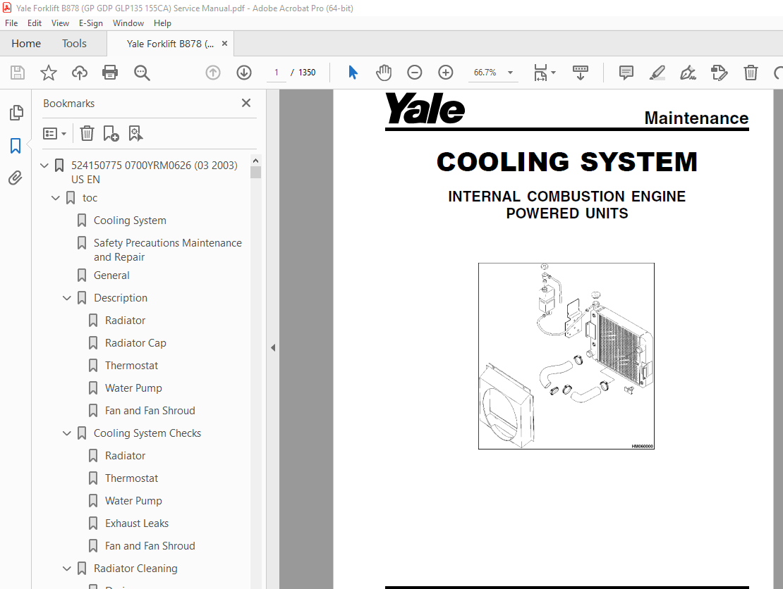
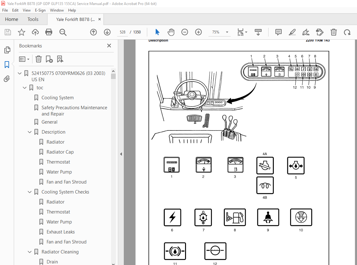
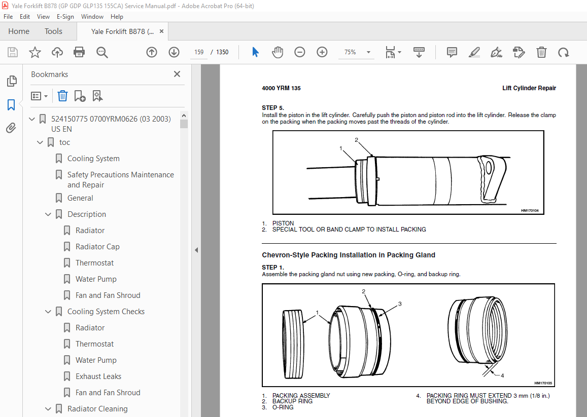
TABLE OF CONTENTS:
Yale Forklift B878 (GP GDP GLP135 155CA) Service Manual – PDF DOWNLOAD
524150775 0700YRM0626 (03 2003) US EN 1
toc 1
Cooling System 1
Safety Precautions Maintenance and Repair 2
General 5
Description 6
Radiator 6
Radiator Cap 6
Thermostat 6
Water Pump 7
Fan and Fan Shroud 7
Cooling System Checks 7
Radiator 7
Thermostat 7
Water Pump 8
Exhaust Leaks 8
Fan and Fan Shroud 8
Radiator Cleaning 8
Drain 8
Clean 8
Fill 9
Troubleshooting 10
524150779 1400YRM0046 (08 2012) US EN 13
toc 13
Differential 13
Safety Precautions Maintenance and Repair 14
General 17
Description 17
Differential Repair 17
Remove 17
Differential Carrier From Axle Housing, Remove 17
Differential and Ring Gear From Differential Carrier, Remove 21
Drive Pinion and Pinion Carrier From Differential Carrier, Remov 23
Disassemble 24
Differential and Ring Gear Assembly, Disassemble 24
Drive Pinion and Pinion Carrier, Disassemble 25
Clean and Inspect 28
Assemble 29
Pinion, Bearings, and Pinion Carrier, Assemble 29
Pinion Bearings, Adjust Preload 29
Press Method 29
Yoke or Flange Method 30
Triple-Lip Seal, Install 31
Pinion Carrier Shim Set, Adjust Thickness (Depth of Pinion) 32
Differential and Ring Gear, Assemble 34
Differential Gears Rotating Torque, Check 36
Differential and Ring Gear Assembly, Install 37
Differential Bearings, Preload Adjust 38
Ring Gear, Runout Check 39
Ring Gear Backlash, Adjust 40
Gear Set, Tooth Contact Pattern Check 42
Thrust Screw, Install and Adjust 45
Install 45
Differential Assembly Into Axle Housing, Install 45
Specifications 46
Troubleshooting 50
tables 13
Table 1 Ring Gear Backlash Adjustment Specifications 41
Table 2 Ring and Pinion Tooth Contact Adjustment 42
Table 3 General Specifications 46
Table 4 Rivet Installation Pressure 46
Table 5 Pinion Adjustment 46
Table 6 Pinion Preload Pressure 47
Table 7 Torque Specifications 48
Table 8 Torque Specifications for Metric Hardware 49
Table 9 Torque Specifications for Metric (Fine) Hardware 49
524150783 1600YRM0326 (03 2007) US EN 53
toc 53
Steering Axle 53
Safety Precautions Maintenance and Repair 54
General 57
Description 57
Steering Axle Assembly Repair 62
Steering Axle GP/GLP/GDP070-110LG/MG (B813), GC/GLC070-120LG/MG 62
Remove 62
Install 62
Steering Axle GDP60-70CA (GP/GLP/GDP135-155CA) (A878, B878), GLP 63
Remove 63
Install 63
Wheels and Hubs Repair (All Units) 64
Remove and Disassemble 64
Clean 64
Inspect 64
Assemble and Install 64
Spindles and Bearings Repair (All Units) 66
Remove 66
Clean 66
Assemble and Install 67
Tie Rods Repair (All Units) 68
Remove 68
Clean 68
Install 68
Steering Cylinder Repair 71
Remove and Disassemble 71
Clean and Inspect 71
Assemble and Install 71
Troubleshooting 72
524150790 2100YRM0103 (03 2007) US EN 77
toc 77
Tilt Cylinders 77
Safety Precautions Maintenance and Repair 78
General 81
Description 81
Tilt Cylinder Repair 81
Remove 81
Disassemble 81
Clean 81
Assemble 82
Tilt Cylinders With O-Ring or Single-Lip Seals 82
Tilt Cylinders 83
Install 84
Tilt Cylinder Leak Check 86
Tilt Cylinder Stroke and Mast Tilt Angle Adjustment 87
Torque Specifications 87
Piston Rod Nut 87
Retainer 87
Troubleshooting 88
tables 77
Table 1 Movement Rates (Maximum) for Tilt Cylinders 86
524150791 2200YRM0002 (01 2016) US EN 93
General 97
Description 98
Alternator Repair 100
Alternator Type A 100
Remove and Disassemble 100
Clean 102
Assemble 102
Install 103
Alternator Type B 106
Remove and Disassemble 106
Clean 106
Assemble 107
Install 108
General Check and Adjustment 108
Low Output Check (Type A or Type B) 109
High Output Check (Type A or Type B) 112
Brushes Circuit Check 113
Delco Alternators 113
Motorola Alternators 113
Diodes Check 114
Diode Bridge Check 114
Delco and Leece-Neville Alternators 114
Motorola Alternators 114
Rotor Field Winding Check 115
Stator Windings Check 116
Voltage Regulator Check 116
Troubleshooting 116
524150792 2200YRM0106 (01 2016) US EN 121
General 125
Description and Operation 126
Starter Repair 130
Remove 130
Disassemble 130
Clean 131
Assemble 131
Install 132
General Checks and Adjustments 132
Troubleshooting 134
524150794 4000YRM0135 (03 2011) US EN 141
toc 141
Lift Cylinders 141
Safety Precautions Maintenance and Repair 142
Safety Procedures When Working Near Mast 145
General 149
Description 149
Lowering Control Valve 149
Cylinders (General) 152
Lift Cylinder Repair 152
Lift Cylinder Removal Without Removing Mast 152
Standard Masts With Main Lift Cylinder Fastened to Crossmember o 152
Standard and Full Free-Lift Masts With Lift Cylinder Fastened to 153
Masts That Have Two Cylinders, Main Lift Cylinder and Free-Lift 154
Disassemble 154
Assemble 154
Lift Cylinder Installation in Mast 156
Standard Masts With Main Lift Cylinder Fastened to Crossmember o 156
Standard and Full Free-Lift Masts With Lift Cylinder Fastened to 156
Chevron-Style Packing 157
Chevron-Style Packing Installation on Piston 157
Chevron-Style Packing Installation in Packing Gland 159
Lift Cylinders for HI VIS® Masts 161
Description 161
Lowering Control Valve 161
Remove 163
Disassemble 164
Assemble 164
Install 166
Main Lift Cylinders 166
Free-Lift Cylinder 166
Lift System Leak Check 166
Specifications 167
Troubleshooting 168
tables 141
Table 1 Cylinder Retainer Torque Specifications and Weight Guid 167
524150797 8000YRM0231 (02 2023) US EN 173
General 179
Threaded Fasteners 179
Nomenclature, Threads 179
Strength Identification 180
Cotter (Split) Pins 181
Fastener Torque Tables 186
Conversion Table 188
524150797 8000YRM0231 (03 2020) US EN 195
General 199
Threaded Fasteners 199
Nomenclature, Threads 199
Strength Identification 200
Cotter (Split) Pins 201
Fastener Torque Tables 206
Conversion Table 208
524153897 0600YRM0590 (04 2014) US EN 215
524153907 1900YRM0097 (05 2012) US EN 267
toc 267
Hydraulic Gear Pumps 267
Safety Precautions Maintenance and Repair 268
Description 271
Operation 272
Flow Control Valve 272
Relief Valve 272
Hydraulic Gear Pump Repair 273
Remove 273
Disassemble 274
Clean 274
Inspect 275
Assemble 278
Install 280
Pump Output Check 280
Method No 1 280
Method No 2 281
Hydraulic System Air Check 282
Troubleshooting 283
524185155 0100YRM0322 (02 2007) US EN 289
toc 289
Frame 289
Safety Precautions Maintenance and Repair 290
General 293
Description 293
Counterweight Repair 294
Remove 294
Install 294
Hood Repair 295
Remove 295
Install 295
Overhead Guard Repair 295
Remove 295
Install 295
Operator Restraint System Repair 296
Automatic Locking Retractor (ALR) 296
Emergency Locking Retractor (ELR) 296
Hydraulic Tank Repair 298
Remove 298
Inspect 298
Small Leaks Repair 298
Large Leaks Repair 298
Clean 298
Steam Method 298
Chemical Solution Method 299
Other Methods of Preparation for Repair 299
Install 299
Fuel Tank Repair 300
Remove 300
Repair 300
Install 300
Radiator Repair 300
Remove 300
Install 300
Engine Repair 301
Remove 301
Install 301
Throttle Pedal Adjustment 303
Perkins 1104C-44(RE) Diesel Engine 303
Safety Labels 304
Cab Repair 306
Cab, Replace 306
Window, Replace 306
Windshield Wipers and Heater 306
tables 289
Table 1 Material Specifications for Cab Windows 306
524185156 1300YRM0324 (10 2003) US EN 311
toc 311
Two-Speed Powershift Transmission 311
Safety Precautions Maintenance and Repair 312
General 315
Mechanical Description 315
Torque Converter 315
Transmission Pump 316
Shaft Assemblies 316
Input Shaft 317
Forward Clutch Shaft 317
Clutch Assemblies 317
Countershaft 324
Output Shaft 324
Hydraulic Operation 325
Torque Converter 325
Seal Rings 326
Control Valve 326
System Pressure Regulator 329
Clutch Pressure Regulator 329
Torque Converter Regulator 330
Inching Spool 330
Direction Spool, Direction Control Lever 330
Direction Spool, Foot Directional Control Pedal 331
Range Spool 332
Drain Spool 332
Accumulator 332
Modulator Spool 332
Operation 333
Lubrication Circuit 333
Foot Directional Control Pedal 334
Oil Flow Diagrams 335
Neutral 335
Forward-Low 335
Forward-Low-Inching 335
Reverse-Low 336
524185157 1300YRM0325 (10 2003) US EN 343
toc 343
Two-Speed Powershift Transmission 343
Safety Precautions Maintenance and Repair 344
General 347
Transmission Repair 347
Transmission and Torque Converter, Remove 347
Transmission, Disassemble 349
Reverse-Low Clutch, Disassemble 352
Reverse-High Clutch, Disassemble 355
Forward-Low Clutch, Disassemble 358
Forward-High Clutch, Disassemble 361
Clean and Inspect 363
Forward Low and High Clutches Assembly 364
Forward Clutches, Assemble 366
Reverse-Low Clutch, Assemble 372
Reverse Clutches, Assemble 374
Transmission, Assemble 381
Torque Converter, Install 387
Control Valve Repair 388
Remove 388
Disassemble 389
Assemble 390
Install 392
Foot Directional Control Pedal 392
Remove and Disassemble 392
Assemble and Install 392
Stall Test 395
Linkage Adjustments 396
Linkage for Inching Pedal GDP60-70CA (GP/GLP/GDP135-155CA) (A878 396
Linkage for Inching Pedal GC/GLC/GDC135-155CA (A879, B879) 399
Linkage for Range Lever – Early Model GDP60-70CA (GP/GLP/GDP135- 401
Linkage for Direction Control Lever – Early Model GDP60-70CA (GP 403
Linkage for Range Lever – Later Model GDP60-70CA (GP\GLP\GDP135- 403
Linkage for Direction Control Lever – Later Model GDP60-70CA (GP 405
Linkage for Range Lever GC/GLC/GDC135-155CA (A879, B879) 407
Linkage for Direction Control Lever GC/GLC/GDC135-155CA (A879, B 407
Oil Pressure Check 409
System Pressure Check Port 410
Torque Converter Check Port 410
Clutch Pressure Check Port 410
Inching Pressure 410
Solenoid Check Ports ( Foot Directional Control Only) 410
Lubrication Pressure Check Ports 410
Specifications 410
Troubleshooting 411
Correct System Pressure: 1300 ±124 kPa ( 189 ±18 psi) 413
Correct Clutch Pressure: 924 ±69 kPa ( 134 ±10 psi) 414
Correct Solenoid Pressure (Foot Directional Control Only): 965 ± 415
Torque Converter Pressure: 834 ±69 kPa ( 121 ±10 psi) 415
Lubrication Pressure: 83 ±21 kPa ( 12 ±3 psi) 416
tables 343
Table 1 Stall Speed Specifications 395
524185159 1400YRM0049 (09 2003) US EN 419
toc 419
Drive Axle 419
Safety Precautions Maintenance and Repair 420
General 423
Description 423
Drive Axle Repair 424
Disassemble 424
Clean 427
Inspect 427
Assemble 428
Torque Specifications 431
Troubleshooting 431
524185160 1600YRM0054 (10 2003) US EN 435
toc 435
Steering Control Unit 435
Safety Precautions Maintenance and Repair 436
General 439
Description 439
Operation 439
Steering Wheel and Column Assembly Repair 441
Steering Column Assembly Repair 441
Type A Steering Column Assembly 441
Remove and Disassemble 441
Assemble and Install 443
Type B Steering Column Assembly 445
Remove and Disassemble 445
Assemble and Install 445
Steering Control Unit 448
Disassemble 448
Clean 451
Assemble 452
System Air Removal 457
Troubleshooting 457
524185161 1800YRM0327 (09 2003) US EN 461
toc 461
Brake System 461
Safety Precautions Maintenance and Repair 462
General 465
Description 465
Operation 466
Brake Booster and Master Cylinder 466
Brake Booster 466
Master Cylinder 467
Service Brake Assembly 468
Parking Brake 469
Brake Shoe Assemblies Repair 470
Remove and Disassemble 470
Clean and Inspect 470
Cleaning Procedures 470
Inspect 470
Assemble and Install 472
Master Cylinder Repair 473
Remove 473
Disassemble 473
Assemble 475
Install 475
Brake Booster Repair 475
Remove 475
Disassemble 475
Clean and Inspect 477
Assemble 477
Install 477
Brake System Air Removal 477
Brake Pedal Adjustment 478
Brake Shoes Adjustment 479
Parking Brake Adjustment 479
Parking Brake Switch Adjustment 479
Brake Booster Relief Valve Check 479
Troubleshooting 480
524185163 1900YRM0328 (09 2003) US EN 485
toc 485
Hydraulic System 485
Safety Precautions Maintenance and Repair 486
General 489
Description and Operation 489
Hydraulic Pumps 490
Main Control Valve 491
Control Valve Lever 491
Steering Control Unit 491
Brake Valve 492
Troubleshooting 492
Lift, Lower, and Tilt Circuit 493
Steering and Brake System 494
524185164 2000YRM0090 (10 2003) US EN 499
toc 499
Main Control Valve 499
Safety Precautions Maintenance and Repair 500
General 503
Description 503
Operation 503
Lift Spool 503
Tilt Spool 503
Tilt Backward 503
Tilt Forward 507
Two-Stage Relief Valve 508
Main Control Valve Repair 509
Remove and Disassemble 509
Clean and Inspect 509
Assemble 509
Install 510
Two-Stage Relief Valve 510
Troubleshooting 511
tables 499
Table 1 Relief Pressures (Oil temperature at 55 to 66 C ( 131 t 510
524185165 2200YRM0143 (02 2007) US EN 515
toc 515
Instrument Panel Indicators and Senders 515
Safety Precautions Maintenance and Repair 516
General 519
Description 520
Internal Combustion Engine Trucks 520
Instrument Cluster Panels at Base of Steering Column, Descriptio 525
Trucks With Instrument Cluster Display Panels, Description 526
Electric Lift Trucks 529
Battery Gauge With Lift Interrupt (Curtis 933/1 and 933/4 Models 530
Battery Gauge With Lift Interrupt and Brush Wear Indicator (GE), 530
EV-100LX Motor Controller Display Panel (ITW), Description 531
Adjustments – General 532
Replacement – General Information 532
Internal Combustion Engine Display Panel Replacement 532
Display Panels Mounted at Base of Steering Column 532
Remove 532
Install 534
Instrument Cluster Display Panels Mounted on Cowl 534
Remove and Install 534
Inner Components, Replace 534
Electric Truck Display Panel Replacement 536
GE and Curtis 933/1 and 933/4 Battery Gauges 536
Controller for Battery Indicator, Replace 536
ITW Display Panel, Replace 536
Remove 536
Sender Replacement 540
Fuel Level Sender 540
Pressure and Temperature Sender 540
Seat Sensor, Operator Presence System (OPS) 541
Remove 541
Install 541
Operator Presence System Module Replacement 541
Remove 541
Install 543
Specifications 544
Meter Specifications 544
Sender Specifications 545
Troubleshooting 546
Meter 546
Troubleshooting for Operator Presence System 547
tables 515
Table 1 Troubleshooting Procedure for Operator Presence Module 547
524185167 4000YRM0329 (09 2010) US EN 553
toc 553
Masts 553
Safety Precautions Maintenance and Repair 554
General 557
Description and Operation 557
General 557
Safety Procedures When Working Near Mast 558
Two-Stage Mast 560
Three-Stage Mast 561
Carriage Repair 562
Remove 562
Sideshift Carriage, Disassemble 564
Sideshift Carriage, Assemble 566
Install 566
Two-Stage Mast Repair 567
Remove 567
Disassemble 569
Clean and Inspect 569
Assemble 570
Install 571
Three-Stage Mast Repair 572
Remove 572
Disassemble 572
Clean and Inspect 573
Assemble 573
Install 574
Mast Operation Check 575
Lift and Tilt System Leaks Check 575
Lift System 575
Tilt System 576
Tilt Cylinder Stroke and Backward Tilt Angle Adjustment 576
Lift Chain Adjustments 577
Mast Adjustments 579
Carriage Adjustment 581
Troubleshooting 582
tables 553
Table 1 Mast Parts Weight 567
Table 2 Hook-Type Carriage Chain Adjustment 578
Table 3 Pin-Type Carriage Chain Adjustment 578
524185168 8000YRM0331 (09 2003) US EN 587
toc 587
Capacities and Specifications 587
Safety Precautions Maintenance and Repair 588
Lift Truck Weights 591
Capacities 591
Tire Sizes 592
Tire Pressure 592
Electrical System 592
Wheel Nut Torque 592
Engine Specifications 593
Hydraulic System 593
Mast Speeds 594
Transmission Oil Pressures 594
Torque Specifications 595
Engine – GM 4 3L V-6 595
Engine – Perkins 1004 4 595
Clutch 595
Manual Transmission 595
Powershift Transmission 595
Speed Reducer 596
Drive Axle 596
Steering System 596
Brake System 596
Hydraulic System 596
Tilt Cylinder 596
Mast 596
524185169 8000YRM0341 (06 2009) US EN 599
toc 599
Periodic Maintenance 599
Safety Precautions Maintenance and Repair 600
General 605
Serial Number Data 605
How to Move Disabled Truck 605
How to Tow Lift Truck 605
How to Put Lift Truck on Blocks 606
How to Raise Drive Tires 606
How to Raise Steering Tires 606
Maintenance Schedule 607
Maintenance Procedures Every 8 Hours or Daily 618
How to Make Checks With Engine Stopped 618
Hydraulic System Oil 618
Engine Oil 619
Drive Belts 619
Intake Manifold Rubber Cap 620
Cooling System 620
Air Filter 620
Fuel System 621
Primary Fuel Filter, Diesel Engine 621
Battery 621
Tires and Wheels 622
Forks 622
Adjust 622
Remove and Install 624
Forks, Mast, and Lift Chains, Inspect 625
Operator Restraint System 626
Automatic Locking Retractor (ALR) 626
Emergency Locking Retractor (ELR) 626
Safety Labels 627
How to Make Checks With Engine Running 628
Gauges, Lights, Horn, and Fuses 628
Oil Level, Powershift Transmission 629
Oil Level, Oil Clutch System, GP/GLP/GDP070-110LG/MG 630
Control Levers and Pedals 630
Lift System Operation 630
Inching/Brake Pedal 630
Service Brakes 630
Parking Brake 631
Steering System 631
Maintenance Procedures Every 250 Hours or 6 Weeks 631
Engine Oil and Filter, GM V-6 Engine 631
Lift Chains, Lubrication 631
Drive Shafts 631
Mast Lubrication 632
Crankcase Breather, GM V-6 632
Air Filter, GM V-6 EPA Compliant Engine 632
Maintenance Procedures Every 350 Hours or 2 Months 633
Drive Belts 633
Perkins Diesel Engine 633
GM V-6 Engine (Early Models) 634
GM V-6 Engine (Late Models) 634
Brake Fluid 636
Lift Chains Wear Check 636
Forks Wear and Damage Check 636
Steering Axle Lubrication 636
Fuel System, Checks and Adjustments 637
Diesel Fuel System 637
LPG Carburetor (Early Models) 637
Gasoline Carburetor (Early Models) 638
Fuel Injection (Late Models) 638
Hydraulic Tank Breather 638
Cooling System, Clean Debris from Radiator Core 638
Maintenance Procedures Every 500 Hours or 3 Months 639
Engine Oil and Filter, Perkins Diesel Engine 639
Crankcase Breather, Perkins Diesel Engine 639
PCV Valve, GM V-6 639
Maintenance Procedures Every 1000 Hours or 6 Months 639
Manifold Heat Valve, GM V-6 (Early Models) 639
Ignition System, GM V-6 639
Valve Clearance Adjustment 639
Fuel Filter, Replace (Diesel Engine) 640
Fuel System Air Removal (Perkins 1004-4 Diesel Engine) 640
Fuel Injection Pump With Vent Tube 640
Fuel Injection Pump With Vent Screw 641
Oil Level Check in Transmission 643
Manual Transmission, GP/GLP/GDP070-110LG/MG 643
Speed Reducer for Powershift Transmission, GP/GLP/GDP070-110LG/M 643
Manual Transmission, GDP60-70CA (GP/GLP/GDP135-155CA) 643
Differential and Drive Axle for Powershift Transmission, GDP60-7 643
Differential, Speed Reducer, and Drive Axle for Manual Transmiss 643
Control Levers and Pedals, Lubricate 643
Crankcase Breather, Replace 643
Cooling System, GM V-6 EPA Compliant Engine 643
Spark Plug Replacement 644
Remove 644
Install 644
LPG Fuel Filter GM V-6 EPA Compliant Engine, Replace 644
Inspect Engine Electrical System, Connectors, and FCVS Connectio 645
Maintenance Procedures Every 2000 Hours or Yearly 646
Hydraulic System 646
Hydraulic Oil and Filter, GP/GLP/GDP070-110LG/MG, Replace 646
Hydraulic Oil and Filter, GDP60-70CA (GP/GLP/GDP135-155CA), Repl 646
Oil Change and Oil Filter Replacement, Powershift Transmission, 646
Oil Change, Manual Transmission, GP/GLP/GDP070-110LG/MG 647
Oil Change, Manual Transmission, GDP60-70CA (GP/GLP/GDP135-155CA 647
Oil Change, Speed Reducer, Powershift Transmission, GP/GLP/GDP07 647
Oil and Filter Change, Oil Clutch System, GP/GLP/GDP070-110LG/MG 647
Oil Change, Differential and Drive Axle, Powershift Transmission 647
Oil Change, Differential, Speed Reducer, and Drive Axle, Manual 648
Cooling System 648
PCV Valve, GM V-6 648
Service Brakes 648
LPG Filter, Replace 649
Gasoline Fuel Filter, Replace 649
Hood Latch Check, GP/GLP/GDP070-110LG/MG 649
Air Filter Element, GM V-6 EPA Compliant Engine 650
Oxygen Sensor GM V-6 EPA Compliant Engine 650
Inspect Low Pressure Regulator (LPR) for Oil Buildup and Leaks 650
Check Throttle Shaft for Sticking 651
Inspect Exhaust Manifold and Piping for Leaks 651
Test LPG/GAS Regulator Pressure 651
Safety Procedures When Working Near Mast 651
Lift Chain Adjustments 654
Fuel Injectors Repair 656
Lift and Tilt System Leak Check 656
Lift Cylinders, Leak Check 656
Tilt Cylinders, Leak Check 657
Welding Repairs 657
Overhead Guard Changes 658
Wheel and Tire Replacement 659
Remove Wheels From Lift Truck 659
Remove Wheels From Tire 659
Remove Tire From Two-Piece Wheel 660
Remove Tire From Three- and Four-Piece Wheels 662
Install Wheel in Tire 664
Install Three- or Four-Piece Wheel in Tire 664
Install Two-Piece Wheel in Tire 666
Add Air to Pneumatic Tires 667
Wheels, Install 667
Solid Rubber Tires Repair 668
Wheel, Tire Remove 668
Wheel, Tire Install 670
SIT Tire, Change for GDP60-70CA (A878, and B878), and GP/GLP/GDP 672
Remove SIT Solid Tire From Wheel 672
Install SIT Solid Tire on Wheel 673
Adhesives and Sealants 674
Hydraulic Oil, Lubricant, and Coolant Specifications 674
tables 599
Table 1 Maintenance Schedule 608
Table 2 Hook-Type Carriage Chain Adjustment 654
Table 3 Pin-Type Carriage Chain Adjustment 655
524185171 8000YRM0519 (06 2007) US EN 677
toc 677
Diagrams 677
Safety Precautions Maintenance and Repair 678
524201517 0600YRM1070 (06 2007) US EN 755
toc 755
Perkins Diesel Engines 755
Safety Precautions Maintenance and Repair 756
General 763
General Safety Rules 763
Description 764
Engine Serial Number Codes 766
Engine Data 766
Engine Removal and Installation 767
Cylinder Head Assembly Repair 768
Engine Breather 768
Remove 768
Install 768
Valve Cover 769
Remove 769
Install 769
Rocker Arm Assembly 770
Remove 770
Disassemble 770
Inspect 771
Assemble 771
Install 771
Valve Clearance Adjustments 772
Valve Springs 772
Cylinder Head Assembly 773
Remove 773
Inspect 774
Install 775
Valves and Valve Springs 777
Remove 777
Inspect 778
Install 778
Valve Guides 778
Inspect 778
Remove 779
Install 779
Valve Seats 780
Inspect 780
Repair 780
New Valve Seats, Install 781
Piston and Connecting Rod Assemblies Repair 782
General 782
Rod Bearings 782
Remove 782
Install 783
Piston and Connecting Rod Assembly 784
Service Note 784
Remove 784
Disassemble 784
Inspect 784
How to Select Correct Replacements 786
Assemble 786
Install 787
Piston Cooling Jets 789
Remove 789
Install 789
Crankshaft Assembly Repair 790
General 790
Crankshaft Pulley 790
Remove 790
Inspect 790
Install 790
Rear Oil Seal 791
Remove 791
Install 791
Crankshaft Flange Wear Sleeve 793
Remove 793
Install 793
Main Bearings 794
Remove 794
Inspect 794
Install 794
Thrust Washers 795
Crankshaft Axle Movement, Check 795
Remove 796
Install 796
Crankshaft 797
Remove 797
Inspect 797
Install 797
Crankshaft Timing Ring 799
Remove 799
Install 799
Flywheel 800
Remove 800
Ring Gear, Replace 800
Install 800
Flywheel Housing 801
Remove 801
Install 801
Timing Case and Timing Gears Repair 802
General 802
Timing Case Cover 802
Remove 802
Install 802
Front Oil Seal 803
Remove, With Timing Case Installed 803
Install, With Timing Case Installed 803
Remove, With Timing Case Removed 804
Install, With Timing Case Removed 804
Crankshaft Pulley Wear Sleeve, Install 805
Fuel Pump Gear 805
Remove 805
Install 807
Idler Gear and Hub 808
Remove 808
Disassemble 808
Standard Idler Gear and Hub Assembly 808
Heavy Duty Idler Gear and Hub Assembly 809
Assemble 809
Standard Idler Gear and Hub Assembly 809
Heavy Duty Idler Gear and Hub Assembly 809
Install 810
Camshaft Gear 811
Remove 811
Install 811
Crankshaft Gear 811
Remove 811
Install 811
Timing Case 812
Remove 812
Install 813
Power Take-Off (PTO) Adaptor 814
Remove 814
Disassemble 814
Assemble 815
Install 815
Camshaft and Tappets 815
Remove 815
Install 816
Cylinder Block Assembly Repair 816
General 816
Cylinder Block 816
Disassemble 816
Inspect 817
Assemble 817
Cylinder Bore 817
Inspect 817
Cylinder Liner Condition Check 817
Engine Timing 818
General 818
How to Set Number One Piston to TDC on Compression Stroke 818
Fuel Injection Pump Timing, Check 819
Fuel Injection Pump Timing, Adjust 820
Lubrication System Repair 822
General 822
Oil Filter, Replace 822
Oil Filter Head 823
Remove 823
Install 823
Oil Sump 823
Remove 823
Install 824
Oil Pump 825
Remove 825
Inspect 825
Install 826
Oil Strainer and Suction Pipe 826
Remove 826
Install 826
Relief Valve 827
Remove 827
Install 827
Dipstick Tube 827
Remove and Install 827
Fuel System Repair 828
General 828
Cold Start Advance Unit (KSB) 828
Typical Fuel System 830
Fuel Filter 831
Remove 831
Install 831
Fuel Injectors 832
Remove 832
Install 833
Fuel System Air Removal 834
Bosch EVPE Fuel Injection Pump 834
General 834
Remove 835
Install 836
Cooling System Repair 836
General 836
Thermostat 838
Remove 838
Install 838
Test 838
Coolant Pump 838
Remove 838
Disassemble 839
Assemble 840
Install 841
Fan 842
Remove and Install 842
Fan Drive 842
Remove 842
Install 842
Oil Cooler 842
Remove 842
Disassemble and Assemble 843
Install 843
Coolant Bypass Hose 843
Removal 843
Install 843
Electrical Equipment Repair 844
Drive Belt 844
Check 844
Adjust 844
Remove 844
Install 844
Alternator 845
Remove 845
Install 845
Fault Diagnosis 845
Normal Operation: 845
If the Warning Lamp is Not Illuminated When the Ignition Switch 846
If the Warning Light Continues to be Illuminated When the Altern 846
Starter Motor 847
Remove 847
Install 847
Test 847
Starting Aid 847
Remove 847
Install 848
Check 848
Power Supply Continuity 848
Operation 848
Pressure Sensor 849
Remove 849
Install 850
Temperature Sensor 850
Remove 850
Install 851
Engine Specifications 851
Cylinder Head Assembly 851
Piston and Connecting Rods 854
Crankshaft Assembly 856
Crankshaft Overhaul 856
Timing Case and Drive Assembly 858
Engine Block Assembly 859
Lubrication System 860
Fuel System 860
Cooling System 861
Flywheel and Housing 862
Electrical Equipment 862
Torque Specifications 862
Special Torque Specifications 863
Cylinder Head Assembly 863
Piston and Connecting Rod Assemblies 863
Crankshaft Assembly 863
Timing Case and Drive Assembly 863
Cylinder block 863
Fuel System 863
Lubrication System 863
Cooling System 864
Flywheel and Housing 864
Electrical Equipment 864
Special Tools 864
Troubleshooting 868
tables 755
Table 1 Cylinder Head 851
Table 2 Valve Guides 852
Table 3 Inlet Valves 852
Table 4 Exhaust Valves 853
Table 5 Valve Springs 854
Table 6 Tappets 854
Table 7 Rocker Arm Shaft 854
Table 8 Rocker Arms and Bushings 854
Table 9 Pistons 854
Table 10 Piston Rings 854
Table 11 Piston Pins 855
Table 12 Connecting Rods 855
Table 13 Small End Bushings 855
Table 14 Connecting Rod Bearings 856
Table 15 Piston Cooling Jets 856
Table 16 Crankshaft Overhaul Specifications 857
Table 17 Maximum Variation (Run-out) 858
Table 18 Camshaft 858
Table 19 Camshaft Thrust Washer 858
Table 20 Camshaft Gear 858
Table 21 Gear for Fuel Pump 858
Table 22 Crankshaft Gear 858
Table 23 Idler Gear and Hub 859
Table 24 Timing Gear Backlash Values 859
Table 25 Cylinder Block 859
Table 26 Oil Pump 860
Table 27 Idler Gear for Oil Pump 860
Table 28 Relief Valve 860
Table 29 Oil Filter 860
Table 30 Bosch Fuel Injection Pump 860
Table 31 Fuel Injector Settings 860
Table 32 Fuel Pump 861
Table 33 Fuel Filter 861
Table 34 Coolant Pump 861
Table 35 Thermostat 861
Table 36 Fan Drive Housing 861
Table 37 Limits for Flywheel Run Out and Alignment (Total Indic 862
Table 38 Alternator 862
Table 39 Starter Motor 862
Table 40 Starting Aids 862
Table 41 List of Possible Causes 869
524208004 0900YRM1088 (05 2006) US EN 873
toc 873
Electronic Controlled LPG/Gasoline Fuel System 873
Safety Precautions Maintenance and Repair 874
General 879
Fuel System Warnings and Cautions 879
Glossary 880
Description and Operation of LPG Fuel System 884
Propane Fuel System 884
LPG Fuel Tank 886
Service Line 886
Fuel Filter 886
Low Pressure Lock-Off (LPL) 886
Low Pressure Regulator (LPR) 887
Air Fuel Mixer 887
Throttle Control Device 888
Drive By Cable 888
Three-Way Catalytic (TWC) Muffler 889
Electronic Control Module (ECM) 889
Heated Exhaust Gas Oxygen (HEGO) Sensor 890
Description and Operation of Gasoline Fuel System 892
Gasoline Fuel System Throttle Body Injection (TBI), 3 0L Engine 892
Gasoline Multi-Point Fuel Injection (MPFI) System, 4 3L Only 892
Gasoline Fuel Storage Tank 892
Gasoline Fuel Pump 892
Fuel Filter 892
Fuel Pressure Regulator, 3 0L Only 895
Fuel Rail and Pressure Regulator, 4 3L Only 896
Fuel Injector 896
Throttle Control Device 896
Drive By Cable 896
Three-Way Catalytic Muffler 897
Electronic Control Module (ECM) 897
Heated Exhaust Gas Oxygen (HEGO) Sensor 899
LPG Fuel System Repair 899
Propane Fuel System Pressure Relief 899
Propane Fuel System Leak Test 899
Propane Fuel Filter Replacement 900
Remove 900
Install 900
Low Pressure Lock-Off (LPL) Replacement 900
Remove 900
Install 900
Pressure Trim Valve (PTV) Replacement 902
Remove 902
Install 902
Low Pressure Regulator 902
Remove 902
Install 902
Fuel Trim Valve (FTV) Solenoid Replacement 903
Remove 903
Install 903
Temperature Manifold Absolute Pressure (TMAP) 903
Remove 903
Install 903
Throttle Body Replacement 905
Remove 905
Install 905
Mixer Replacement 907
Remove 907
Install 907
Coolant Hose Replacement 907
Remove 907
Install 908
Vapor Hose Replacement 908
Remove 908
Install 908
Balance Line Hose Replacement 908
Remove 908
Install 908
PTV Hose Replacement 908
Remove 908
Install 908
FTV Hose Replacement 909
Remove 909
Install 909
Throttle Position Sensor (TPS) Replacement 909
Foot Pedal Position (FPP) Sensor Replacement 911
Electronic Control Module (ECM) Replacement 914
Remove 914
Install 914
Heated Exhaust Gas Oxygen (HEGO) Sensor Replacement 914
Remove 914
Install 915
Three-Way Catalytic Muffler (TWC) Replacement 915
Remove 915
Install 915
Restricted Exhaust System Diagnosis 915
Exhaust System Description 915
Tools Required 915
Diagnostic Tool 915
Check at Heated Exhaust Gas Oxygen Sensor (HEGO) 915
Gasoline Fuel System Repair 916
Gasoline MPFI and TBI Fuel System Pressure Relief 916
Gasoline Fuel System Leak Test 917
Throttle Body Injector (TBI) Assembly Replacement, 3 0L Only 917
Remove 917
Install 917
Throttle Body Assembly Replacement, 3 0L Only 919
Remove 919
Install 919
Throttle Body Assembly Replacement, 4 3L Only 920
Remove 920
Install 920
Fuel Rail Replacement, Gasoline 4 3L Only 921
Remove 921
Install 921
Injector Replacement, Gasoline 4 3L Only 921
Remove 921
Install 921
Injector Replacement, Gasoline 3 0L Only 923
Remove 923
Install 923
Temperature Manifold Absolute Pressure (TMAP) Replacement 923
Remove 923
Install 923
Throttle Position Sensor (TPS) Replacement 923
Foot Pedal Position (FPP) Sensor Replacement 926
Electronic Control Module (ECM) Replacement 929
Remove 929
Install 929
Heated Exhaust Gas Oxygen (HEGO) Sensor Replacement 930
Remove 930
Install 930
Three-Way Catalytic Muffler (TWC) Replacement 930
Remove 930
Install 930
Restricted Exhaust System Diagnosis 930
Exhaust System Description 930
Tools Required 930
Diagnostic Tool 930
Check at Heated Exhaust Gas Oxygen Sensor (HEGO) 931
LPG System Diagnosis 931
Fuel System Description 931
Diagnostic Aids 932
Tools Required 932
Duty Cycle Monitoring Tool 932
Diagnostic Tool 932
Pressure Gauges 932
Test Description 932
Gasoline System Diagnosis 940
Fuel System Description, 3 0L Only 940
Fuel System Description, 4 3L Only 940
Diagnostic Aids 941
Tools Required 941
Diagnostic Tool 941
Test Description 941
LPG Symptom Diagnosis 948
Gasoline Symptom Diagnosis 962
Wire Harness Repair 973
On Vehicle Service Wiring Harness Repair 973
Connectors and Terminals 973
Twisted/Shielded Cable Repair 974
Twisted Leads Repair 975
Micro-Pack 976
Metri-Pack 976
Remove 976
Weather-Pack 978
Weather-Pack Terminal Repair 979
tables 873
Table 1 TPS Replacement Procedure 909
Table 2 FPP Replacement Procedure 912
Table 3 TPS Replacement Procedure 924
Table 4 FPP Replacement Procedure 927
Table 5 LPG Fuel System Diagnosis 932
Table 6 Fuel Control Diagnosis 936
Table 7 Gasoline Fuel System Diagnosis, 3 0L Only 942
Table 8 Gasoline Fuel System Diagnosis, 4 3L Only 945
Table 9 Preliminary Checks 948
Table 10 Intermittent 949
Table 11 No Start 950
Table 12 Hard Start 952
Table 13 Cuts Out or Misses 953
Table 14 Hesitation, Sag, or Stumble 954
Table 15 Backfire 955
Table 16 Lack of Power, Sluggishness, or Sponginess 956
Table 17 Poor Fuel Economy 957
Table 18 Rough, Unstable, Incorrect Idle, or Stalling 959
Table 19 Surges or Chuggles 961
Table 20 Preliminary Checks 962
Table 21 Intermittent 963
Table 22 No Start 964
Table 23 Hard Start 965
Table 24 Cuts Out or Misses 966
Table 25 Hesitation, Sag, or Stumble 967
Table 26 Backfire 968
Table 27 Lack of Power, Sluggishness, or Sponginess 969
Table 28 Poor Fuel Economy 970
Table 29 Rough, Unstable, Incorrect Idle, or Stalling 971
Table 30 Surges or Chuggles 972
524208009 2200YRM1090 (04 2005) US EN 983
toc 983
Electronic Control Module (ECM) Diagnostic Troubleshooting 983
Safety Precautions Maintenance and Repair 984
General 993
Description of ECM Based Diagnostics 993
Definition of Terms 993
Diagnostics Overview of the Spectrum Fuel System 993
Malfunction Indicator Lamp (MIL) 993
Spectrum Diagnostic Trouble Codes (DTC) 994
Using a Laptop Computer to Diagnose the Spectrum System 994
Installing the Spectrum Diagnostic Software 994
Connecting a Laptop Computer to the Spectrum System 994
Diagnostic Communication Error 995
Diagnostic Trouble Codes 995
Checking Diagnostic Trouble Codes 996
Clearing Diagnostic Trouble Codes 996
DATA Stream 996
Reading Sensor and Actuator Values 996
Graphing and Data Logging 997
Ignition System Test 998
Disabling Ignition Outputs 998
Injector Test 999
Disabling Injectors 999
Throttle Test 1000
Using a Diagnostic Jumper to Diagnose the ECI System 1001
On-Board Diagnostics System Check/Malfunction Indicator Lamp 1002
Circuit Description 1002
Preliminary and Intermittent Checks 1005
GM 3 0L Wiring Schematics and Connectors 1007
GM 3 0L Diagnostic Trouble Codes 1021
DTC 111 – IAT High Voltage Motorola® TMAP 1021
Circuit Description 1021
Conditions for Setting the DTC 1021
DTC 112 – IAT Low Voltage Motorola® TMAP 1024
Circuit Description 1024
Conditions for Setting the DTC 1024
DTC 113 – IAT Higher Than Expected 1 Motorola® TMAP 1027
Circuit Description 1027
Conditions for Setting the DTC 1027
Diagnostic Aids 1027
DTC 114 – IAT Higher Than Expected 2 Motorola® TMAP 1028
Circuit Description 1028
Conditions for Setting the DTC 1028
Diagnostic Aids 1028
DTC 115 – Oil Pressure Low 1029
Circuit Description 1029
Conditions for Setting the DTC 1029
DTC 121 – ECT Voltage High 1032
Circuit Description 1032
Conditions for Setting the DTC 1033
DTC 122 – ECT Voltage Low 1036
Circuit Description 1036
Conditions for Setting the DTC 1036
DTC 123 – ECT Higher Than Expected 1 1038
Circuit Description 1038
Conditions for Setting the DTC 1038
DTC 124 – ECT Higher Than Expected 2 1040
Circuit Description 1040
Conditions for Setting the DTC 1040
DTC 131 – MAP High Pressure Motorola® TMAP 1042
Circuit Description 1042
Conditions for Setting the DTC 1042
Diagnostic Aids 1042
DTC 132 – MAP Low Voltage Motorola® TMAP 1044
Circuit Description 1044
Conditions for Setting the DTC 1044
DTC 134 – BP High Pressure Motorola® TMAP 1048
Circuit Description 1048
Conditions for Setting the DTC 1048
DTC 135 – BP Low Pressure Motorola® TMAP 1050
Circuit Description 1050
Conditions for Setting the DTC 1050
DTC 142 – Crank Sync Noise 1054
Circuit Description 1054
Conditions for setting the DTC 1054
DTC 143 – Never Crank Synced At Start 1057
Circuit Description 1057
Conditions for Setting the DTC 1057
DTC 144 – Camshaft Sensor Loss 1060
Circuit Description 1060
Conditions for Setting the DTC 1060
DTC 145 – Camshaft Sensor Noise 1063
Circuit Description 1063
Conditions for Setting the DTC 1063
DTC 211 – Closed Loop Multiplier High (LPG) 1066
Circuit Description 1066
Conditions for Setting the DTC 1066
Diagnostic Aids 1066
DTC 212 – HO 2 S Open/Inactive 1068
Circuit Description 1068
Conditions for Setting the DTC 1068
DTC 221 – Closed Loop Multiplier High (Gasoline) 1072
Circuit Description 1072
Conditions for Setting the DTC 1072
Diagnostic Aids 1073
DTC 222 – Closed Loop Multiplier Low (Gasoline) 1074
Circuit Description 1074
Conditions for Setting the DTC 1074
Diagnostic Aids 1074
DTC 224 – Closed Loop Multiplier Low (LPG) 1076
Circuit Description 1076
Conditions for Setting the DTC 1076
Diagnostic Aids 1077
DTC 241 – Adaptive Lean Fault (High Limit-Gasoline) 1078
Circuit Description 1078
Conditions for Setting the DTC 1078
Diagnostic Aids 1079
DTC 242 – Adaptive Rich Fault (Low Limit-Gasoline) 1082
Circuit Description 1082
Conditions for Setting the DTC 1082
Diagnostic Aids 1082
DTC 243 – Adaptive Learn High (LPG) 1084
Circuit Description 1084
Conditions for Setting the DTC 1084
Diagnostic Aids 1084
DTC 244 – Adaptive Learn Low (LPG) 1088
Circuit Description 1088
Conditions for Setting the DTC 1088
Diagnostic Aids 1088
DTC 261 – System Voltage High 1090
Circuit Description 1090
Conditions for Setting the DTC 1090
DTC 262 – System Voltage Low 1092
Circuit Description 1092
Conditions for Setting the DTC 1092
DTC 411 – Injector Driver 1 Open 1095
Circuit Description 1095
Conditions for Setting the DTC 1095
DTC 412 – Injector Driver 1 Shorted 1098
Circuit Description 1098
Conditions for Setting the DTC 1098
DTC 511 – COP Failure 1101
Circuit Description 1101
Conditions for Setting the DTC 1101
DTC 512 – Invalid Interrupt 1103
Circuit Description 1103
Conditions for Setting the DTC 1103
DTC 513 – A/D Loss 1105
Circuit Description 1105
Conditions for Setting the DTC 1105
DTC 514 – RTI 1 Loss 1107
Circuit Description 1107
Conditions for Setting the DTC 1107
DTC 515 – Flash Checksum Invalid 1109
Circuit Description 1109
Conditions for Setting the DTC 1109
DTC 516 – Ram Failure 1111
Circuit Description 1111
Conditions for Setting the DTC 1111
DTC 531 – External 5V Ref Lower Than Expected 1113
Circuit Description 1113
Conditions for Setting the DTC 1113
DTC 532 – External 5V Ref Higher Than Expected 1116
Circuit Description 1116
Conditions for Setting the DTC 1116
DTC 555 – RTI 2 Loss 1118
Circuit Description 1118
Conditions for Setting the DTC 1118
DTC 556 – RTI 3 Loss 1120
Circuit Description 1120
Conditions for Setting the DTC 1120
DTC 611 – FPP High Voltage 1122
Circuit Description 1122
Conditions for Setting the DTC 1122
DTC 612 – FPP Low Voltage 1125
Circuit Description 1125
Conditions for Setting the DTC 1125
DTC 631 – TPS1 Signal Voltage High 1129
Circuit Description 1129
Conditions for Setting the DTC 1129
DTC 632 – TPS1 Signal Voltage Low 1132
Circuit Description 1132
Conditions for Setting the DTC 1132
DTC 638 – Throttle Unable To Close 1134
Circuit Description 1134
Conditions for Setting the DTC 1134
Diagnostic Aids 1134
DTC 651 – Maximum Govern Speed Override 1138
Circuit Description 1138
Conditions for Setting the DTC 1138
Diagnostic Aids 1138
DTC 652 – Fuel Rev Limit 1140
Circuit Description 1140
Conditions for Setting the DTC 1140
Diagnostic Aids 1140
DTC 653 – Spark Rev Limit 1143
Circuit Description 1143
Conditions for Setting the DTC 1143
Diagnostic Aids 1143
GM 4 3L Wiring Schematics and Connectors 1146
GM 4 3L Diagnostic Trouble Codes 1163
DTC 111 – IAT High Voltage Bosch® TMAP 1163
Circuit Description 1163
Conditions for Setting the DTC 1163
DTC 111 – IAT High Voltage Motorola® TMAP 1166
Circuit Description 1166
Conditions for Setting the DTC 1166
DTC 112 – IAT Low Voltage Bosch® TMap 1168
Circuit Description 1168
Conditions for Setting the DTC 1168
DTC 112 – IAT Low Voltage Motorola® TMAP 1171
Circuit Description 1171
Conditions for Setting the DTC 1171
DTC 113 – IAT Higher Than Expected 1 Bosch® TMAP 1174
Circuit Description 1174
Conditions for Setting the DTC 1174
Diagnostic Aids 1174
DTC 113 – IAT Higher Than Expected 1 Motorola® TMAP 1175
Circuit Description 1175
Conditions for Setting the DTC 1175
Diagnostic Aids 1175
DTC 114 – IAT Higher Than Expected 2 Bosch® TMAP€ 1176
Circuit Description 1176
Conditions for Setting the DTC 1176
Diagnostic Aids 1176
DTC 114 – IAT Higher Than Expected 2 Motorola® TMAP 1177
Circuit Description 1177
Conditions for Setting the DTC 1177
Diagnostic Aids 1177
DTC 115 – Oil Pressure Low 1178
Circuit Description 1178
Conditions for Setting the DTC 1178
DTC 121 – ECT Voltage High 1181
Circuit Description 1181
Conditions for Setting the DTC 1182
DTC 122 – ECT Voltage Low 1184
Circuit Description 1184
Conditions for Setting the DTC 1184
DTC 123 – ECT Higher Than Expected 1 1187
Circuit Description 1187
Conditions for Setting the DTC 1187
DTC 124 – ECT Higher Than Expected 2 1189
Circuit Description 1189
Conditions for Setting the DTC 1189
DTC 131 – MAP High Pressure Bosch® TMAP 1190
Circuit Description 1190
Conditions for Setting the DTC 1190
Diagnostic Aids 1190
DTC 131 – MAP High Pressure Motorola® TMAP 1194
Circuit Description 1194
Conditions for Setting the DTC 1194
Diagnostic Aids 1194
DTC 132 – MAP Low Voltage Bosch® TMAP 1197
Circuit Description 1197
Conditions for Setting the DTC 1197
DTC 132 – MAP Low Voltage Motorola® TMAP 1200
Circuit Description 1200
Conditions for Setting the DTC 1200
DTC 134 – BP High Pressure Bosch® TMAP 1204
Circuit Description 1204
Conditions for Setting the DTC 1204
DTC 134 – BP High Pressure Motorola® TMAP 1206
Circuit Description 1206
Conditions for Setting the DTC 1206
DTC 135 – BP Low Pressure Bosch® TMAP 1208
Circuit Description 1208
Conditions for Setting the DTC 1208
DTC 135 – BP Low Pressure Motorola® TMAP 1212
Circuit Description 1212
Conditions for Setting the DTC 1212
DTC 142 – Crank Sync Noise 1216
Circuit Description 1216
Conditions for setting the DTC 1216
DTC 143 – Never Crank Synced At Start 1219
Circuit Description 1219
Conditions for Setting the DTC 1219
DTC 144 – Camshaft Sensor Loss 1222
Circuit Description 1222
Conditions for Setting the DTC 1222
DTC 145 – Camshaft Sensor Noise 1225
Circuit Description 1225
Conditions for Setting the DTC 1225
DTC 211 – Closed Loop Multiplier High (LPG) 1228
Circuit Description 1228
Conditions for Setting the DTC 1228
Diagnostic Aids 1228
DTC 212 – HO 2 S Open/Inactive 1230
Circuit Description 1230
Conditions for Setting the DTC 1230
DTC 221 – Closed Loop Multiplier High (Gasoline) 1234
Circuit Description 1234
Conditions for Setting the DTC 1234
Diagnostic Aids 1234
DTC 222 – Closed Loop Multiplier Low (Gasoline) 1236
Circuit Description 1236
Conditions for Setting the DTC 1236
Diagnostic Aids 1237
DTC 224 – Closed Loop Multiplier Low (LPG) 1238
Circuit Description 1238
Conditions for Setting the DTC 1238
Diagnostic Aids 1239
DTC 241 – Adaptive Lean Fault (High Limit-Gasoline) 1240
Circuit Description 1240
Conditions for Setting the DTC 1240
Diagnostic Aids 1241
DTC 242 – Adaptive Rich Fault (Low Limit-Gasoline) 1244
Circuit Description 1244
Conditions for Setting the DTC 1244
Diagnostic Aids 1245
DTC 243 – Adaptive Learn High (LPG) 1247
Circuit Description 1247
Conditions for Setting the DTC 1247
Diagnostic Aids 1248
DTC 244 – Adaptive Learn Low (LPG) 1250
Circuit Description 1250
Conditions for Setting the DTC 1250
Diagnostic Aids 1251
DTC 261 – System Voltage High 1252
Circuit Description 1252
Conditions for Setting the DTC 1252
DTC 262 – System Voltage Low 1254
Circuit Description 1254
Conditions for Setting the DTC 1254
DTC 511 – COP Failure 1257
Circuit Description 1257
Conditions for Setting the DTC 1257
DTC 512 – Invalid Interrupt 1259
Circuit Description 1259
Conditions for Setting the DTC 1259
DTC 513 – A/D Loss 1261
Circuit Description 1261
Conditions for Setting the DTC 1261
DTC 514 – RTI 1 Loss 1263
Circuit Description 1263
Conditions for Setting the DTC 1263
DTC 515 – Flash Checksum Invalid 1265
Circuit Description 1265
Conditions for Setting the DTC 1265
DTC 516 – Ram Failure 1267
Circuit Description 1267
Conditions for Setting the DTC 1267
DTC 531 – External 5V Ref Lower Than Expected 1269
Circuit Description 1269
Conditions for Setting the DTC 1269
DTC 532 – External 5V Ref Higher Than Expected 1272
Circuit Description 1272
Conditions for Setting the DTC 1272
DTC 555 – RTI 2 Loss 1274
Circuit Description 1274
Conditions for Setting the DTC 1274
DTC 556 – RTI 3 Loss 1276
Circuit Description 1276
Conditions for Setting the DTC 1276
DTC 611 – FPP High Voltage 1278
Circuit Description 1278
Conditions for Setting the DTC 1278
DTC 612 – FPP Low Voltage 1282
Circuit Description 1282
Conditions for Setting the DTC 1282
DTC 631 – TPS1 Signal Voltage High 1286
Circuit Description 1286
Conditions for Setting the DTC 1286
DTC 632 – TPS1 Signal Voltage Low 1289
Circuit Description 1289
Conditions for Setting the DTC 1289
DTC 638 – Throttle Unable To Close 1292
Circuit Description 1292
Conditions for Setting the DTC 1292
Diagnostic Aids 1293
DTC 651 – Maximum Govern Speed Override 1295
Circuit Description 1295
Conditions for Setting the DTC 1295
Diagnostic Aids 1295
DTC 652 – Fuel Rev Limit 1298
Circuit Description 1298
Conditions for Setting the DTC 1298
Diagnostic Aids 1298
DTC 653 – Spark Rev Limit 1300
Circuit Description 1300
Conditions for Setting the DTC 1300
Diagnostic Aids 1300
Wire Harness Repair 1303
On Vehicle Service Wiring Harness Repair 1303
Connectors and Terminals 1303
Twisted/Shielded Cable Repair 1304
Twisted Leads Repair 1305
Micro-Pack 1306
Metri-Pack 1306
Remove 1306
Weather-Pack 1308
Weather-Pack Terminal Repair 1308
tables 983
Table 1 OBD System Check 1003
Table 2 Preliminary Checks 1005
Table 3 Intermittent Checks 1006
Table 4 Communication Port C002 1007
Table 5 Coil Connector C003 1007
Table 6 Fuel System Interface C004 1007
Table 7 Oil Pressure Connector C005 1008
Table 8 Distributor Connector C006 1008
Table 9 Magnetic Pickup Connector C007 1008
Table 10 Heated Oxygen Sensor C008 1008
Table 11 Throttle Position Sensor Connector C009 1009
Table 12 Foot Pedal Position Connector C010 1009
Table 13 Governor Motor Connector C011 1009
Table 14 TMAP Connector C012 1009
Table 15 Starter Solenoid C013 1010
Table 16 Engine Coolant Temperature C014 1010
Table 17 Battery Connector C015 1010
Table 18 Alternator Connection C016 1010
Table 19 Battery Connector C017 1010
Table 20 Alternator Connector C018 1011
Table 21 Instrument Panel Connector C019 1011
Table 22 Instrument Panel Connector C020 1011
Table 23 Instrument Panel Connector C021 1012
Table 24 Fuel Trim Valve Connector C022 1012
Table 25 Fuel Lockoff Connector C023 1012
Table 26 Pressure Trim Valve Connector C024 1013
Table 27 Throttle Body Injector Connector C025 1013
Table 28 Relay and Fuse Center 1013
Table 29 DTC 111 – IAT Voltage High (Motorola® TMAP) 1022
Table 30 DTC 112 – IAT Low Voltage (Motorola® TMAP) 1025
Table 31 DTC 115 – Oil Pressure Low 1030
Table 32 Temperature Resistance 1032
Table 33 DTC 121 – ECT VOLTAGE HIGH 1033
Table 34 DTC 122 – ECT Voltage Low 1037
Table 35 DTC 123 – ECT Higher Than Expected 1 1039
Table 36 DTC 124 – ECT Higher Than Expected 2 1041
Table 37 DTC 131 – MAP HIGH PRESSURE (Motorola® TMAP) 1043
Table 38 DTC 132 – MAP Low Voltage (Motorola® TMAP) 1045
Table 39 DTC 134 – BP High Pressure (Motorola® TMAP) 1049
Table 40 DTC 135 – BP Low Pressure (Motorola® TMAP) 1050
Table 41 DTC 142 – Crank Sync Noise 1054
Table 42 DTC 143 – Never Crank Synced At Start 1057
Table 43 DTC 144 – Camshaft Sensor Loss 1060
Table 44 DTC 145 – Camshaft Sensor Noise 1063
Table 45 DTC 211 – Closed Loop Multiplier High (LPG) 1067
Table 46 DTC 212 – HO 2 S Open/Inactive 1069
Table 47 DTC 221 – Closed Loop Multiplier High (Gasoline) 1073
Table 48 DTC 222 – Closed Loop Multiplier Low (Gasoline) 1076
Table 49 DTC 224 – Closed Loop Multiplier Low (LPG) 1078
Table 50 DTC 241 – Adaptive Lean Fault (High Limit-Gasoline) 1080
Table 51 DTC 242 – Adaptive Rich Fault (Low Limit-Gasoline) 1083
Table 52 DTC 243 – Adaptive Learn High (LPG) 1086
Table 53 DTC 244 – Adaptive Learn Low (LPG) 1089
Table 54 DTC 261 – System Voltage High 1091
Table 55 DTC 262 – System Voltage Low 1093
Table 56 DTC 411 – Injector Driver 1 Open 1096
Table 57 DTC 412 – Injector Driver 1 Shorted 1099
Table 58 DTC 511 – COP Failure 1102
Table 59 DTC 512 – Invalid Interrupt 1104
Table 60 DTC 513 – A/D Loss 1106
Table 61 DTC 514 – RTI 1 Loss 1108
Table 62 DTC 515 – Flash Checksum Invalid 1110
Table 63 DTC 516 – Ram Failure 1112
Table 64 DTC 531 – External 5V Ref Lower Than Expected 1114
Table 65 DTC 532 – External 5 V Ref Higher Than Expected 1116
Table 66 DTC 555 – RTI 2 Loss 1119
Table 67 DTC 556 – RTI 3 Loss 1121
Table 68 DTC 611 – FPP High Voltage 1122
Table 69 DTC 612 – FPP Low Voltage 1126
Table 70 DTC 631 – TPS1 Signal Voltage High 1130
Table 71 DTC 632 – TPS1 Signal Voltage Low 1133
Table 72 DTC 638 – Throttle Unable To Close 1135
Table 73 DTC 651 – Maximum Govern Speed Override 1139
Table 74 DTC 652 – Fuel Rev Limit 1141
Table 75 DTC 653 – Spark Rev Limit 1144
Table 76 Communication Port C002 1146
Table 77 Injector Connector C003 1146
Table 78 Injector Connector C004 1146
Table 79 Oil Pressure Connector C005 1147
Table 80 Throttle Position Sensor 1 Connector C006 1147
Table 81 Foot Pedal Position Connector C006A 1147
Table 82 Coil Connector C007 1147
Table 83 Module Connector C008 1148
Table 84 Crank Sensor Connector C009 1148
Table 85 EGO Sensor Connector C010 1148
Table 86 Cam Connector C011 1148
Table 87 Throttle Connector C012 1149
Table 88 Bosch TMAP Connector C013 (Gasoline Fuel System Only) 1149
Table 89 Motorola TMAP Connector C013 (LPG Fuel System Only) 1149
Table 90 Starter Solenoid Connector C014 1149
Table 91 ECT Connector C015 1150
Table 92 Starter Relay C016 1150
Table 93 Power Relay C017 1150
Table 94 Fuel Pump Relay C018 1150
Table 95 Battery Connector C019 1150
Table 96 Alternator Connector C020 1150
Table 97 Alternator Connector C021 1151
Table 98 Instrument Panel Connector C022 1151
Table 99 Instrument Panel Connector C023 1151
Table 100 Instrument Panel Connector C024 1152
Table 101 Fuel Trim Valve Connector C025 1152
Table 102 Fuel Lockoff Connector C026 1152
Table 103 Pressure Trim Valve Connector C027 1153
Table 104 Injector 1 Connector C028 1153
Table 105 Injector 2 Connector C029 1153
Table 106 Injector 3 Connector C030 1153
Table 107 Injector 4 Connector C031 1154
Table 108 Injector 5 Connector C032 1154
Table 109 Injector 6 Connector C033 1154
Table 110 Relay and Fuse Center 1155
Table 111 DTC 111 – IAT Voltage High (Bosch® TMAP) 1164
Table 112 DTC 111 – IAT Voltage High (Motorola® TMAP) 1167
Table 113 DTC 112 – IAT Low Voltage (Bosch® TMAP) 1169
Table 114 DTC 112 – IAT Low Voltage (Motorola® TMAP) 1172
Table 115 DTC 115 – Oil Pressure Low 1179
Table 116 Temperature Resistance 1181
Table 117 DTC 121 – ECT VOLTAGE HIGH 1182
Table 118 DTC 122 – ECT Voltage Low 1185
Table 119 DTC 123 – ECT Higher Than Expected 1 1188
Table 120 DTC 124 – ECT Higher Than Expected 2 1190
Table 121 DTC 131 – MAP High Pressure (Bosch® TMAP) 1191
Table 122 DTC 131 – MAP HIGH PRESSURE (Motorola® TMAP) 1195
Table 123 DTC 132 – MAP Low Voltage (Bosch® TMAP) 1198
Table 124 DTC 132 – MAP Low Voltage (Motorola® TMAP) 1201
Table 125 DTC 134 – BP High Pressure (Bosch® TMAP) 1205
Table 126 DTC 134 – BP High Pressure (Motorola® TMAP) 1207
Table 127 DTC 135 – BP Low Pressure (Bosch® TMAP) 1208
Table 128 DTC 135 – BP Low Pressure (Motorola® TMAP) 1212
Table 129 DTC 142 – Crank Sync Noise 1216
Table 130 DTC 143 – Never Crank Synced At Start 1219
Table 131 DTC 144 – Camshaft Sensor Loss 1222
Table 132 DTC 145 – Camshaft Sensor Noise 1225
Table 133 DTC 211 – Closed Loop Multiplier High (LPG) 1229
Table 134 DTC 212 – HO 2 S Open/Inactive 1231
Table 135 DTC 221 – Closed Loop Multiplier High (Gasoline) 1235
Table 136 DTC 222 – Closed Loop Multiplier Low (Gasoline) 1238
Table 137 DTC 224 – Closed Loop Multiplier Low (LPG) 1240
Table 138 DTC 241 – Adaptive Lean Fault (High Limit-Gasoline) 1242
Table 139 DTC 242 – Adaptive Rich Fault (Low Limit-Gasoline) 1245
Table 140 DTC 243 – Adaptive Learn High (LPG) 1248
Table 141 DTC 244 – Adaptive Learn Low (LPG) 1251
Table 142 DTC 261 – System Voltage High 1253
Table 143 DTC 262 – System Voltage Low 1255
Table 144 DTC 511 – COP Failure 1258
Table 145 DTC 512 – Invalid Interrupt 1260
Table 146 DTC 513 – A/D Loss 1262
Table 147 DTC 514 – RTI 1 Loss 1264
Table 148 DTC 515 – Flash Checksum Invalid 1266
Table 149 DTC 516 – Ram Failure 1268
Table 150 DTC 531 – External 5V Ref Lower Than Expected 1270
Table 151 DTC 532 – External 5 V Ref Higher Than Expected 1272
Table 152 DTC 555 – RTI 2 Loss 1275
Table 153 DTC 556 – RTI 3 Loss 1277
Table 154 DTC 611 – FPP High Voltage 1279
Table 155 DTC 612 – FPP Low Voltage 1283
Table 156 DTC 631 – TPS1 Signal Voltage High 1287
Table 157 DTC 632 – TPS1 Signal Voltage Low 1290
Table 158 DTC 638 – Throttle Unable To Close 1293
Table 159 DTC 651 – Maximum Govern Speed Override 1296
Table 160 DTC 652 – Fuel Rev Limit 1299
Table 161 DTC 653 – Spark Rev Limit 1301
524208014 2200YRM1097 (03 2020) US EN 1313
Series Code / Model Designation Reference Table 1317
Description 1318
Distributor Ignition (DI) System 1318
Crankshaft Position (CKP) Sensor 1318
Camshaft Position (CMP) Sensor 1318
Ignition Coil and Ignition Control Module (ICM) 1318
Secondary Ignition Components 1318
Spark Plugs and Wires 1319
Spark Plug Wire Inspection 1319
Spark Plug Wire Replacement 1319
Remove 1319
Install 1320
Spark Plug Inspection 1320
Usage 1320
Inspection 1320
Visual Inspection 1322
Spark Plug Replacement 1322
Remove 1322
Install 1322
Distributor Repair 1323
Inspect 1323
Overhaul 1323
Disassemble 1323
Assemble 1326
Replace 1327
Remove 1327
Install Procedure 1 1329
Install Procedure 2 1330
Ignition Coil Replacement 1331
Remove 1331
Install 1331
Ignition Control Module Replacement 1332
Remove 1332
Install 1332
Starter Replacement 1333
Remove 1333
Install 1336
Sensors and Switches 1337
Gas and LPG Trucks 1337
Crankshaft Position (CKP) Sensor 1337
Remove 1337
Install 1337
Camshaft Position (CMP) Sensor 1338
Remove 1338
Install 1340
Oil Pressure Sensor 1340
Remove 1340
Install 1341
Manifold Absolute Pressure (MAP)/Manifold Air Temperature (MAT) Sensor 1342
Remove 1342
Install 1342
Engine Coolant Temperature (ECT) Sensor 1343
Remove 1343
Install 1344
Air Flow Restriction Switch 1344
Remove 1344
Install 1345
Specifications and Special Tools 1346
More products