$41.95
Yale Forklift B883 (ESC030-40AC) Service Manual – PDF DOWNLOAD
Yale Forklift B883 (ESC030-40AC) Service Manual – PDF DOWNLOAD
FILE DETAILS:
Yale Forklift B883 (ESC030-40AC) Service Manual – PDF DOWNLOAD
Language : English
Pages : 1746
Downloadable : Yes
File Type : PDF
IMAGES PREVIEW OF THE MANUAL:


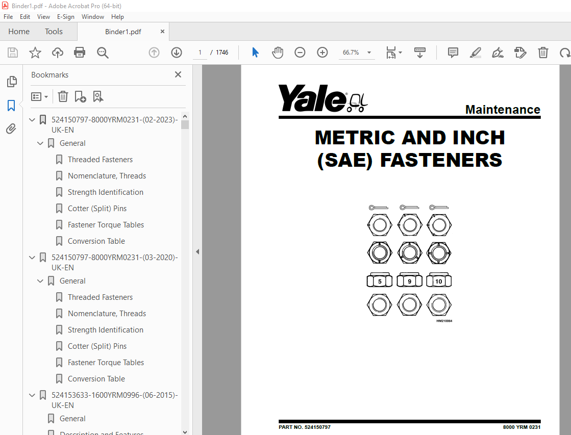
TABLE OF CONTENTS:
Yale Forklift B883 (ESC030-40AC) Service Manual – PDF DOWNLOAD
524150797-8000YRM0231-(02-2023)-UK-EN 1
General 7
Threaded Fasteners 7
Nomenclature, Threads 7
Strength Identification 8
Cotter (Split) Pins 9
Fastener Torque Tables 14
Conversion Table 16
524150797-8000YRM0231-(03-2020)-UK-EN 23
General 27
Threaded Fasteners 27
Nomenclature, Threads 27
Strength Identification 28
Cotter (Split) Pins 29
Fastener Torque Tables 34
Conversion Table 36
524153633-1600YRM0996-(06-2015)-UK-EN 43
General 47
Description and Features 47
On-Demand Steering Circuit 47
Description 48
A883 48
B883 / C883
49
Steering Control Handle 50
Remove 50
Install 50
Steering Sensor 50
Test 50
Remove 50
Install 50
Steering Control Unit (SCU) 51
Description 51
Inspect 51
Remove 51
Repair 53
Replace 53
Steering Pump and Motor Assembly 54
Description 54
Inspect 54
Remove 54
Repair 55
Disassemble 55
Assemble 56
Install 57
Power Steering Pump 57
Description 57
Repair 57
Disassemble 57
Assemble 58
Steer Unit Actuator-Kordel™ 59
Description 59
Inspect 59
Steering Actuator 59
Remove 59
Disassemble 61
Clean 61
Inspect 61
Assemble 63
Install 64
Steer Tire and Wheel 64
Remove 64
Install 65
Wheel Hub 65
Remove 65
Clean 65
Inspect 66
Install 66
Checks and Adjustments 66
Air in System 66
Operation Check 67
Steering Pressure 67
Troubleshooting 68
524158040-2240YRM0001-(01-2023)-UK-EN 73
General 79
Battery Type 79
Lead-Acid Batteries 79
Lithium-Ion Batteries 80
Specific Gravity 80
Chemical Reaction in a Cell 80
Electrical Terms 82
Battery Selection 83
Battery Voltage 84
Battery as a Counterweight 84
Battery Ratings 84
Kilowatt-Hours 84
Battery Maintenance 85
Safety Procedures 85
Maintenance Records 85
New Battery 85
Cleaning Battery 86
Adding Water to Battery 88
Hydrometer 88
Battery Temperature 89
Charging Battery 90
Types of Battery Charges 91
Methods of Charging 92
Troubleshooting Charger 93
Knowing When Battery Is Fully Charged 93
Where to Charge Batteries 93
Equipment Needed 93
Battery Connectors 94
Battery Care 94
Troubleshooting 96
524158040-2240YRM0001-(03-2020)-UK-EN 101
General 105
Battery Type 105
Lead-Acid Batteries 105
Lithium-Ion Batteries 106
Specific Gravity 106
Chemical Reaction in a Cell 106
Electrical Terms 108
Battery Selection 108
Battery Voltage 109
Battery as a Counterweight 110
Battery Ratings 110
Kilowatt-Hours 110
Battery Maintenance 110
Safety Procedures 110
Maintenance Records 111
New Battery 111
Cleaning Battery 111
Adding Water to Battery 113
Hydrometer 114
Battery Temperature 115
Charging Battery 116
Types of Battery Charges 116
Methods of Charging 118
Troubleshooting Charger 118
Knowing When Battery Is Fully Charged 119
Where to Charge Batteries 119
Equipment Needed 119
Battery Connectors 120
Battery Care 120
Troubleshooting 122
524183085-2200YRM1058-(04-2011)-UK-EN 127
toc 127
Troubleshooting and Adjustments Using the AC Controls Program (E 127
Safety Precautions Maintenance and Repair 128
General 131
Computer Requirements 131
Software, Install 131
Language Selection 131
Demo Mode 132
Connect PC to Lift Truck 136
Starting AC Controls Program 138
Lift Truck Control Setup 143
Change Lift Truck Serial Number or Hourmeter 143
Setting Factory Default Values or Changing Lift Truck Parameters 144
Create New Custom Lift Truck Configuration 150
Lift Truck Configuration Properties 153
Import New Lift Truck Configuration From Disk 156
Delete Custom Lift Truck Configuration or Password File 158
Dash Display 161
Custom Display Languages 161
Download Display Language 163
Clear Operator Log 163
Password Functions 166
Enable/Disable Password and Lift Truck Inspection Functions 166
Truck Inspection Checklist 166
Password 166
Password Properties 166
Create New Password File 171
Download Passwords 172
Upload Passwords 174
Reports Menu 176
Devices Report 176
Custom Report 176
Password Report 176
Operator Report 183
Current Settings Report 186
Status Code Report 190
Status Codes Log 193
Troubleshooting 195
Diagnostics 195
Help Menu 198
General 198
Contents 198
Technical Support 198
About Electric Truck AC Controls Program 198
524223769-2200YRM1128-(01-2023)-UK-EN 205
Series Code / Model Designation Reference Table 213
General 215
Deutsch Crimping Tool 216
How to Strip a Wire for Use With Deutsch Crimping Tool 216
How to Crimp With the Deutsch Crimping Tool 217
Calibration Test for the Deutsch Crimping Tool 219
Deutsch Connectors 221
DT, DTM, and DTP Series Connectors 221
HD Series Connectors 264
Metri-Pack Connectors 286
Remove and Install 286
Micro-Pack Connectors 289
Weather-Pack Connectors 290
AMPSEAL Crimping Tools 292
AMP Hand Crimping Tool With Certi-Crimp 292
Description 292
Stripping Wire for Use with AMP Hand Crimping Tool 293
Insulation Crimp Adjustment 294
Maintenance and Inspection for AMP Hand Crimping Tool 294
AMP Hand Crimping Tool 294
Crimp Height Inspection 294
How to use AMP Hand Crimping Tool 295
AMP Pro-Crimper II Tool 295
Description 295
Remove and Install Die Set and Locator Assembly 296
Stripping Wire for Use With AMP PRO-CRIMPER II Tool 296
Contact Support Adjustment 297
Crimp Height Adjustment 298
Maintenance and Inspection Procedures 298
PRO-CRIMPER II Tool 298
Crimp Height Inspection 298
How to Use AMP PRO-CRIMPER II Tool 299
AMPSEAL Connector Assemblies 300
Description for Plug Connector Assembly 300
Seal Plug 301
Contact Crimping 301
Description for Plug Connector and Header Assembly 306
Voltage Reading 309
Seal Plug 309
Contact Crimping 309
AMP Superseal 1 5 Crimping Tools 316
Mini Mic Receptacle and Tab Contacts 316
Description 316
Crimping Conditions and Measurements 316
Insertion of Rubber Seal on Cable 318
AMP Hand Application Tool 323
Description 323
Maintenance and Inspection 323
Crimp Height Inspection 323
Crimp Height Adjustment 324
How to Use AMP Hand Application Tool 324
AMP Pro-Crimper II Tool 325
Description 325
Remove and Install Die Set and Locator Assembly 325
Adjustments 326
Contact Support 326
Crimp Height 327
Inspections and Maintenance 328
Crimp Height Inspection 328
Visual Inspection 328
Maintenance 329
How to Use Pro-Crimper II Tool 329
AMP Superseal 1 5 Connector Assemblies 330
Description 330
Repair and Maintenance 337
Panel Mount Option 337
AMP Fastin-Faston Hand Tools 338
Description – AMP Double Action Hand Tool 338
Maintenance and Inspection Procedures 338
Daily Maintenance 338
Periodic Tool Inspection 339
Lubrication 339
Visual Inspection 339
Crimp Height Inspection 339
Certi-Crimp Ratchet Inspection 340
How to Use AMP Double Action Hand Tool 341
Description – AMP Extraction Tool 342
Maintenance and Inspection 343
How to Use AMP Extraction Tool 343
AMP Fastin-Faston Receptacles and Housings 345
Description 345
Wire Repair 353
Wire Splicing Requirements 353
Deutsch Jiffy Splice 354
Twisted/Shielded Cable and Leads Repair 360
Special Tools 362
524223769-2200YRM1128-(07-2020)-UK-EN 371
Series Code / Model Designation Reference Table 377
General 380
Deutsch Crimping Tool 380
How to Strip a Wire for Use With Deutsch Crimping Tool 380
How to Crimp With the Deutsch Crimping Tool 381
Calibration Test for the Deutsch Crimping Tool 383
Deutsch Connectors 385
DT, DTM, and DTP Series Connectors 385
HD Series Connectors 427
Metri-Pack Connectors 450
Remove and Install 450
Micro-Pack Connectors 452
Weather-Pack Connectors 453
AMPSEAL Crimping Tools 455
AMP Hand Crimping Tool With Certi-Crimp 455
Description 455
Stripping Wire for Use with AMP Hand Crimping Tool 455
Insulation Crimp Adjustment 456
Maintenance and Inspection for AMP Hand Crimping Tool 456
AMP Hand Crimping Tool 456
Crimp Height Inspection 456
How to use AMP Hand Crimping Tool 457
AMP Pro-Crimper II Tool 457
Description 457
Remove and Install Die Set and Locator Assembly 458
Stripping Wire for Use With AMP PRO-CRIMPER II Tool 459
Contact Support Adjustment 459
Crimp Height Adjustment 460
Maintenance and Inspection Procedures 460
PRO-CRIMPER II Tool 460
Crimp Height Inspection 460
How to Use AMP PRO-CRIMPER II Tool 461
AMPSEAL Connector Assemblies 462
Description for Plug Connector Assembly 462
Seal Plug 463
Contact Crimping 463
Description for Plug Connector and Header Assembly 468
Voltage Reading 470
Seal Plug 470
Contact Crimping 470
AMP Superseal 1 5 Crimping Tools 477
Mini Mic Receptacle and Tab Contacts 477
Description 477
Crimping Conditions and Measurements 477
Insertion of Rubber Seal on Cable 479
AMP Hand Application Tool 484
Description 484
Maintenance and Inspection 484
Crimp Height Inspection 484
Crimp Height Adjustment 485
How to Use AMP Hand Application Tool 485
AMP Pro-Crimper II Tool 486
Description 486
Remove and Install Die Set and Locator Assembly 487
Adjustments 487
Contact Support 487
Crimp Height 488
Inspections and Maintenance 489
Crimp Height Inspection 489
Visual Inspection 489
Maintenance 490
How to Use Pro-Crimper II Tool 490
AMP Superseal 1 5 Connector Assemblies 491
Description 491
Repair and Maintenance 498
Panel Mount Option 498
AMP Fastin-Faston Hand Tools 499
Description – AMP Double Action Hand Tool 499
Maintenance and Inspection Procedures 499
Daily Maintenance 499
Periodic Tool Inspection 500
Lubrication 500
Visual Inspection 500
Crimp Height Inspection 500
Certi-Crimp Ratchet Inspection 501
How to Use AMP Double Action Hand Tool 502
Description – AMP Extraction Tool 503
Maintenance and Inspection 503
How to Use AMP Extraction Tool 504
AMP Fastin-Faston Receptacles and Housings 505
Description 505
Wire Repair 512
Wire Splicing Requirements 512
Deutsch Jiffy Splice 513
Twisted/Shielded Cable and Leads Repair 518
Special Tools 521
524319496-2100YRM1382-(02-2018)-UK-EN 529
Safety Procedures When Working Near Mast 537
General 539
Description 540
Tilt Cylinder Repair for 2 0-5 5T Trucks 540
Remove 540
Disassemble 542
Inspect 543
Clean 543
Assemble 543
Install 545
Tilt Cylinders, Adjust 545
Tilt Cylinder Leak Check 548
Tilt Cylinder Repair
for 1 0-2 0T Trucks 549
Remove 549
Disassemble 551
Inspect 553
Clean 553
Assemble 553
Install 553
Tilt Cylinders, Adjust 554
Tilt Cylinders Leak Check 555
Lift Cylinder Repair
for 2 0-3 5T Trucks 556
Main Lift Cylinders 556
Remove 556
Two-Stage FFL 556
Three-Stage FFL 558
Four-Stage FFL 558
Two-Stage LFL 559
Disassemble 559
Two-Stage FFL 559
Three-Stage FFL 561
Four-Stage FFL 561
Two-Stage LFL 563
Clean 564
Inspect 564
Assemble 564
Two-Stage FFL 564
Three-Stage FFL 564
Four-Stage FFL 565
Two-Stage LFL 565
Install 566
Two-Stage FFL 566
System Air Bleed Procedures 566
Three-Stage FFL 566
Four-Stage FFL 567
Two-Stage LFL 567
Lift Cylinder Repair for Lift Truck Model ERP15VT (G807) 568
Main Lift Cylinder 568
Remove 568
Main Lift Cylinders – Two-Stage FFL Mast 568
Left-Hand Main Lift Cylinder – Three-Stage FFL Mast 570
Right-Hand Main Lift Cylinder – Three-Stage FFL Mast 574
Main Lift Cylinder – Two-Stage LFL Mast 574
Disassemble 577
Main Lift Cylinders – Two-Stage FFL Mast 577
Main Lift Cylinder – Three-Stage FFL Mast 579
Main Lift Cylinder – Two-Stage LFL Mast 579
Clean 580
Inspect 580
Assemble 581
Main Lift Cylinder – Two-Stage FFL Mast 581
Main Lift Cylinder – Three-Stage FFL Mast 581
Main Lift Cylinder – Two-Stage LFL Mast 581
Install 582
Main Lift Cylinder – Two-Stage FFL Mast 582
Left-Hand Main Lift Cylinder – Three-Stage FFL Mast 582
Right-Hand Main Lift Cylinder – Three-Stage FFL Mast 583
Main Lift Cylinder – Two-Stage LFL Mast 584
System Air Bleed Procedures 585
All Main Lift Cylinders 585
Lift Cylinder Repair for 1 5-2 0T Trucks 585
Main Lift Cylinder 585
Remove 585
Two-Stage FFL 586
Three-Stage FFL 586
Two-Stage LFL 587
Four-Stage FFL 589
Disassemble 590
Two-Stage FFL 590
Three-Stage FFL 592
Two-Stage LFL 592
Four-Stage FFL 593
Clean 596
Inspect 596
Assemble 596
Two-Stage FFL 596
Three-Stage FFL 597
Two-Stage LFL 597
Four-Stage FFL 598
Install 599
Two-Stage FFL 599
System Air Bleed Procedures 599
Three-Stage FFL Mast 599
Two-Stage LFL 600
Four-Stage FFL 600
Mast and Carriage Install for Two-Stage FFL, Three-Stage FFL, and Two-Stage LFL 601
Mast and Carriage Installation for Four-Stage FFL 601
Lift Cylinder Repair
for 4 0-5 5T Trucks 602
Main Lift Cylinders 602
Remove 602
Two-Stage FFL 602
Three-Stage FFL 604
Two-Stage LFL 604
Disassemble 605
Two-Stage FFL 605
Three-Stage FFL 607
Two-Stage LFL 608
Clean 609
Inspect 609
Assemble 609
Two-Stage FFL 609
Three-Stage FFL 610
Two-Stage LFL 610
Install 611
Two-Stage FFL 611
System Air Bleed Procedures 611
Three-Stage FFL 611
Two-Stage LFL 612
Free-Lift Cylinder Repair
for 2 0-3 5T Trucks 613
Free-Lift Cylinder 613
Remove 613
Two and Three-Stage FFL Mast 613
Four-Stage FFL For Lift Truck ERC22-356VG (ERC045-070VG) (A968) 614
Disassemble 616
Two and Three-Stage FFL Mast 616
Four-Stage FFL Mast for Lift Truck ERC22-356VG (ERC045-070VG) (A968) 617
Clean 617
Inspect 617
Assemble 618
Two and Three-Stage FFL Mast 618
Four-Stage FFL Mast for Lift Truck ERC22-356VG (ERC045-070VG) (A968) 618
Install 619
Two and Three-Stage FFL Mast 619
Four-Stage FFL Mast for Lift Truck ERC22-35VG (ERC045-070VG) (A968) 619
Free Lift Cylinder Repair for Lift Truck Model ERP15VT (G807) 620
Free-Lift Cylinder 620
Remove 620
Three-Stage FFL Mast 620
Disassemble 622
Clean 623
Inspect 623
Assemble 623
Install 623
Free Lift Cylinder Repair
for 1 5-2 0T Trucks 624
Free-Lift Cylinder 624
Remove 624
Two and Three-Stage FFL Mast 624
Four-Stage FFL Mast 626
Disassemble 628
Two-Stage and Three-Stage FFL Masts 628
Four Stage FFL Mast 629
Clean 630
Inspect 630
Assemble 630
Two-Stage and Three-Stage FFL Masts 630
Four-Stage FFL Mast 631
Install 631
Two-Stage and Three-Stage FFL Masts 631
Four-Stage FFL Mast 631
All Masts 633
Free-Lift Cylinder Repair
for 4 0-5 5T Trucks 634
Free-Lift Cylinder 634
Remove 634
Two and Three-Stage FFL Mast 634
Disassemble 635
Two and Three-Stage FFL Mast 635
Clean 636
Inspect 636
Assemble 636
Two and Three-Stage FFL Mast 636
Install 637
Two and Three-Stage FFL Mast 637
Sideshift Cylinder Repair
for 1 5-3 5T Trucks Prior to December 2016 637
Remove 637
Disassemble 641
Clean and Inspect 643
Assemble and Install 643
Sideshift Cylinder Repair
for 1 5-3 5T Trucks After December 2016 644
Remove 644
Disassemble 648
Clean and Inspect 650
Assemble and Install 650
Integral Side-Shift Cylinder Gland Leak Checks 652
Sideshift Cylinder Repair
for 4 0-5 5T Trucks 653
Remove 653
Disassemble 653
Clean and Inspect 655
Assemble and Install 655
Fork Positioner Cylinder Repair Prior to December 2016 655
Remove 655
Disassemble 656
Clean 658
Inspect 658
Assemble 659
Install 659
Fork Positioner Cylinder Adjustment 659
Fork Positioner Cylinder Repair After December 2016 660
Remove 660
Disassemble 660
Clean 663
Inspect 663
Assemble 664
Install 664
Fork Positioner Cylinder Adjustment 664
Lift Cylinder Leak Check 665
Seal Kit Installation 665
External Installation (Seal and Back-Up Ring) 666
Internal Installation (Piston Rod Assembly) 666
Torque Specifications for Lift Truck Models ERC22-35VG (ERC045-070VG) (A968) and ERP22-25VL (ERP045-070VL) (A976) 666
Tilt Cylinders 666
Piston Rod Nut 666
Gland 667
Tilt Cylinder Mounting Capscrew 667
Tilt Cylinder Rod End Capscrew 667
Main and Free-Lift Cylinder 667
Sideshift Cylinder 667
Fork Positioner Cylinder 667
Torque Specifications for Lift Truck Model ERP15VT (G807) 667
Tilt Cylinders 667
Main and Free-Lift Cylinders 667
Sideshift Cylinder 668
Torque Specifications for Lift Truck Models ERP16-20VT (ERP030-040VT) (G807), ERP16-20VF (ERP30-40VF) (A955), ESC030-40AC (B883),ESC030-40AD (C883) 668
Tilt Cylinders 668
Main and Free-Lift Cylinders 668
Sideshift Cylinder 669
Fork Positioner Cylinder 669
Torque Specifications for Lift Truck Model ERP40-50VM, ERP50-55VM6 (ERP080-120VM, ERP100VML) (A985) 669
Tilt Cylinders 669
Main and Free-Lift Cylinder 669
Sideshift Cylinder 669
Torque Specifications for Lift Truck Model ERC40-55VH, ERC50VHS (ERC80-120VH, ERC100VHS) (A938) 669
Tilt Cylinder 670
Main and Free Lift Cylinder 670
Sideshift Cylinder 670
524319496-2100YRM1382-(07-2023)-UK-EN 673
Safety Procedures When Working Near Mast 683
General 686
Description 686
Tilt Cylinder Repair for 2 0-5 5T Trucks 687
Remove 687
Disassemble 689
Inspect 690
Clean 690
Assemble 690
Install 692
Tilt Cylinders, Adjust 692
Tilt Cylinder Leak Check 695
Tilt Cylinder Repair
for 1 0-2 0T Trucks 696
Remove 696
Disassemble 699
Inspect 701
Clean 701
Assemble 701
Install 701
Tilt Cylinders, Adjust 702
Tilt Cylinders Leak Check 703
Lift Cylinder Repair
for 2 0-3 5T Trucks 705
Main Lift Cylinders 705
Remove 705
Two-Stage FFL 705
Three-Stage FFL 707
Four-Stage FFL 707
Two-Stage LFL 708
Disassemble 708
Two-Stage FFL 708
Three-Stage FFL 710
Four-Stage FFL 712
Two-Stage LFL 713
Clean 714
Inspect 714
Assemble 714
Two-Stage FFL 714
Three-Stage FFL 715
Four-Stage FFL 715
Two-Stage LFL 716
Install 716
Two-Stage FFL 716
System Air Bleed Procedures 716
Three-Stage FFL 717
Four-Stage FFL 717
Two-Stage LFL 718
Lift Cylinder Repair for Lift Truck Model ERP15VT (G807) 719
Main Lift Cylinder 719
Remove 719
Main Lift Cylinders – Two-Stage FFL Mast 719
Left-Hand Main Lift Cylinder – Three-Stage FFL Mast 721
Right-Hand Main Lift Cylinder – Three-Stage FFL Mast 725
Main Lift Cylinder – Two-Stage LFL Mast 725
Disassemble 728
Main Lift Cylinders – Two-Stage FFL Mast 728
Main Lift Cylinder – Three-Stage FFL Mast 730
Main Lift Cylinder – Two-Stage LFL Mast 731
Clean 732
Inspect 732
Assemble 732
Main Lift Cylinder – Two-Stage FFL Mast 732
Main Lift Cylinder – Three-Stage FFL Mast 733
Main Lift Cylinder – Two-Stage LFL Mast 733
Install 733
Main Lift Cylinder – Two-Stage FFL Mast 733
Left-Hand Main Lift Cylinder – Three-Stage FFL Mast 734
Right-Hand Main Lift Cylinder – Three-Stage FFL Mast 735
Main Lift Cylinder – Two-Stage LFL Mast 736
System Air Bleed Procedures 736
All Main Lift Cylinders 737
Lift Cylinder Repair for 1 5-2 0T Trucks 738
Main Lift Cylinder 738
Remove 738
Two-Stage FFL 738
Three-Stage FFL 738
Two-Stage LFL 739
Four-Stage FFL 741
Disassemble 743
Two-Stage FFL 743
Three-Stage FFL 744
Two-Stage LFL 745
Four-Stage FFL 746
Clean 748
Inspect 749
Assemble 749
Two-Stage FFL 749
Three-Stage FFL 749
Two-Stage LFL 750
Four-Stage FFL 750
Install 751
Two-Stage FFL 751
System Air Bleed Procedures 752
Three-Stage FFL Mast 752
Two-Stage LFL 752
Four-Stage FFL 753
Mast and Carriage Install for Two-Stage FFL, Three-Stage FFL, and Two-Stage LFL 753
Mast and Carriage Installation for Four-Stage FFL 754
Lift Cylinder Repair for 4 0-5 5T Trucks 755
Main Lift Cylinders 755
Remove 755
Two-Stage FFL 755
Three-Stage FFL 757
Two-Stage LFL 757
Disassemble 758
Two-Stage FFL 758
Three-Stage FFL 760
Two-Stage LFL 761
Clean 762
Inspect 762
Assemble 762
Two-Stage FFL 762
Three-Stage FFL 763
Two-Stage LFL 763
Install 764
Two-Stage FFL 764
System Air Bleed Procedures 764
Three-Stage FFL 764
Two-Stage LFL 765
Free-Lift Cylinder Repair for 2 0-3 5T Trucks 766
Free-Lift Cylinder 766
Remove 766
Two and Three-Stage FFL Mast 766
Four-Stage FFL For Lift Truck ERC22-356VG (ERC045-070VG) (A968) 767
Disassemble 769
Two and Three-Stage FFL Mast 769
Four-Stage FFL Mast for Lift Truck ERC22-356VG (ERC045-070VG) (A968) 770
Clean 770
Inspect 771
Assemble 771
Two and Three-Stage FFL Mast 771
Four-Stage FFL Mast for Lift Truck ERC22-356VG (ERC045-070VG) (A968) 771
Install 772
Two and Three-Stage FFL Mast 772
Four-Stage FFL Mast for Lift Truck ERC22-35VG (ERC045-070VG) (A968) 772
Free Lift Cylinder Repair for Lift Truck Model ERP15VT (G807) 774
Free-Lift Cylinder 774
Remove 774
Three-Stage FFL Mast 774
Disassemble 776
Clean 777
Inspect 777
Assemble 777
Install 777
Free Lift Cylinder Repair for 1 5-2 0T Trucks 779
Free-Lift Cylinder 779
Remove 779
Two and Three-Stage FFL Mast 779
Four-Stage FFL Mast 781
Disassemble 784
Two-Stage and Three-Stage FFL Masts 784
Four Stage FFL Mast 784
Clean 785
Inspect 785
Assemble 785
Two-Stage and Three-Stage FFL Masts 785
Four-Stage FFL Mast 786
Install 786
Two-Stage and Three-Stage FFL Masts 786
Four-Stage FFL Mast 787
All Masts 790
Free-Lift Cylinder Repair
for 4 0-5 5T Trucks 791
Free-Lift Cylinder 791
Remove 791
Two and Three-Stage FFL Mast 791
Disassemble 792
Two and Three-Stage FFL Mast 792
Clean 793
Inspect 793
Assemble 793
Two and Three-Stage FFL Mast 793
Install 794
Two and Three-Stage FFL Mast 794
Sideshift Cylinder Repair
for 1 5-3 5T Trucks Prior to December 2016 795
Remove 795
Disassemble 798
Clean and Inspect 800
Assemble and Install 800
Sideshift Cylinder Repair
for 1 5-3 5T Trucks After December 2016 802
Remove 802
Disassemble 805
Clean and Inspect 806
Assemble and Install 807
Integral Side-Shift Cylinder Gland Leak Checks 809
Sideshift Cylinder Repair
for 4 0-5 5T Trucks 810
Remove 810
Disassemble 811
Clean and Inspect 812
Assemble and Install 812
Fork Positioner Cylinder Repair Prior to December 2016 813
Remove 813
Disassemble 813
Clean 816
Inspect 816
Assemble 817
Install 817
Fork Positioner Cylinder Adjustment 817
Fork Positioner Cylinder Repair After December 2016 819
Remove 819
Disassemble 819
Clean 822
Inspect 822
Assemble 823
Install 823
Fork Positioner Cylinder Adjustment 823
Lift Cylinder Leak Check 825
Seal Kit Installation 826
External Installation (Seal and Back-Up Ring) 826
Internal Installation (Piston Rod Assembly) 826
Torque Specifications for Lift Truck Models ERC22-35VG (ERC045-070VG) (A968) and ERP22-25VL (ERP045-070VL) (A976) 827
Tilt Cylinders 827
Piston Rod Nut 827
Gland 827
Tilt Cylinder Mounting Capscrew 827
Tilt Cylinder Rod End Capscrew 827
Main and Free-Lift Cylinder 827
Sideshift Cylinder 827
Fork Positioner Cylinder 827
Torque Specifications for Lift Truck Model ERP15VT (G807) 828
Tilt Cylinders 828
Main and Free-Lift Cylinders 828
Sideshift Cylinder 828
Torque Specifications for Lift Truck Models ERP16-20VT (ERP030-040VT) (G807), ERP16-20VF (ERP30-40VF) (A955), ESC030-40AC (B883),ESC030-40AD (C883) 829
Tilt Cylinders 829
Main and Free-Lift Cylinders 829
Sideshift Cylinder 829
Fork Positioner Cylinder 829
Torque Specifications for Lift Truck Model ERP40-50VM, ERP50-55VM6 (ERP080-120VM, ERP100VML) (A985) 830
Tilt Cylinders 830
Main and Free-Lift Cylinder 830
Sideshift Cylinder 830
Torque Specifications for Lift Truck Model ERC40-55VH, ERC50VHS (ERC80-120VH, ERC100VHS) (A938) 830
Tilt Cylinder 830
Main and Free Lift Cylinder 830
Sideshift Cylinder 830
524327049-0620YRM1385-(02-2023)-UK-EN 833
General 841
Discharging the Capacitors for Lift Truck Models ESC030-040AC (B883), ESC030-040AD (C883) 847
Discharging the Capacitors (All Other Models) 849
Traction Motor Repair 850
For Lift Truck Models , and ERP15-20VT (ERP030-040VT) (G807)ERP16-20VF (ERP30-40VF) (A955), ESC030-040AC (B883) 850
Remove 850
Disassemble 851
Electrical Connector Repair or Replacement 853
Clean 853
Inspect 853
Assemble 854
Install 856
For Lift Truck ERC22-35VG (ERC045-070VG) (A968) and ERC16-20VA (ERC030-040VA) (A969) 858
Remove 858
Disassemble 858
Electrical Connector Repair or Replacement 861
Clean 861
Inspect 861
Assemble 862
Install 862
For Lift Truck ERP2 2-3 5VL (ERP045-070VL) (A976) 862
Remove 862
Disassemble 862
Clean 864
Inspect 864
Assemble 865
Install 865
For Lift Truck ERP40-50VM, ERP50-55VM6 (ERP080120VM, ERP100VML) (A985) 865
Remove 865
Clean 867
Install 867
For Lift Truck ERC40-55VH, ERC50VHS (ERC80-120VH, ERC100VHS) (A938) 867
Remove 867
Disassemble 867
Electrical Connector Repair or Replacement 869
Clean 869
Inspect 869
Assemble 870
Install 871
Traction Motor Repair for 4-5 5T Lift Trucks 872
For Lift Truck ERP40-50VM, ERP50-55VM6 (ERP080120VM, ERP100VML) (A985) 872
Remove 872
Clean 874
Install 874
Hydraulic Motor Repair 875
For Lift Trucks and ERP15-20VT (ERP030-040VT) (G807)ERP16-20VF (ERP30-40VF) (A955)ESC030-040AC (B883), ESC030-040AD (C883) 875
Remove 875
Disassemble 876
Electrical Connector Repair or Replacement 878
Clean 878
Inspect 878
Assemble 879
Install 881
For Lift Truck ERC22-35VG (ERC045-070VG) (A968) 882
Remove 882
Disassemble 884
Standard Motor 884
Enhanced Motor 886
Electrical Connector Repair or Replacement 887
Clean 888
Inspect 888
Assemble 889
Standard Motor 889
Enhanced Motor 889
Install 890
For Lift Truck Models ERP2 2-3 5VL (ERP045-070VL) (A976) and ERC16-20VA (ERC030-040VA) (A969) 890
Remove 890
Disassemble 890
Electrical Connector Repair or Replacement 896
Clean 897
Inspect 897
Assemble 898
Install 899
For Lift Truck ERP40-50VM, ERP50-55VM6 (ERP080-120VM, ERP100VML) (A985) and ERC40-55VH, ERC50VHS (ERC80-120VH, ERC100VHS) (A938) 899
Remove 899
Disassemble 899
Electrical Connector Repair or Replacement 902
Clean 902
Inspect 903
Assemble 903
Install 904
Hydraulic Motor Repair For 4 0-5 5T Lift Trucks 904
Remove 904
Disassemble 904
Electrical Connector Repair or Replacement 906
Clean 906
Inspect 907
Assemble 907
Install 908
Torque Specifications 909
Traction Motor for Lift Trucks and ERP15-20VT (ERP030-040VT) (G807)ERP16-20VF (ERP30-40VF) (A955) 909
Traction Motor for Lift Truck and ERC22-35VG (ERC045-070VG) (A968), ERC16-20VA (ERC030-040VA) (A969),ERC40-55VH, ERC50VHS (ERC80-120VH, ERC100VHS) (A938) 909
Traction Motor for Lift Truck ESC030-040AC (B883), ESC030-040AD (C883) 909
Hydraulic Motor for Lift Trucks and ERP15-20VT (ERP030-040VT) (G807)ERP16-20VF (ERP30-40VF) (A955) 909
Hydraulic Motor for Lift Truck ERC22-35VG (ERC045-070VG) (A968) 909
Hydraulic Motor for Lift Truck ERP22-35VG (ERP045-070VG) (A976) 909
Hydraulic Motor for Lift Truck ERC16-20VA (ERC030-040VA) (A969) 909
Hydraulic Motor for Lift Truck ESC030-040AC (B883), ESC030-040AD (C883) 909
Hydraulic Motor for Lift Truck and ERP40-50VM, ERP50-55VM6 (ERP080-120VM, ERP100VML) (A985)ERC40-55VH, ERC50VHS (ERC80-120VH, ERC100VHS) (A938) 910
524327049-0620YRM1385-(06-2015)-UK-EN 913
General 917
Discharging the Capacitors for Lift Truck Models ESC030-040AC (B883), ESC030-040AD (C883) 924
Discharging the Capacitors (All Other Models) 925
Traction Motor Repair 925
For Lift Truck Models ERP15-20VT (ERP030-040VT) (G807), ERP16-20VF (ERP30-40VF) (A955), and ESC030-040AC (B883) 926
Remove 926
Disassemble 927
Electrical Connector Repair or Replacement 930
Clean 930
Inspect 930
Assemble 931
Install 934
For Lift Truck ERC22-35VG (ERC045-070VG) (A968) and ERC16-20VA (ERC030-040VA) (A969) 936
Remove 936
Disassemble 936
Electrical Connector Repair or Replacement 940
Clean 940
Inspect 940
Assemble 941
Install 941
For Lift Truck ERP2 2-3 5VL (ERP045-070VL) (A976) 941
Remove 941
Disassemble 941
Clean 943
Inspect 943
Assemble 944
Install 944
For Lift Truck ERC40-55VH, ERC50VHS (ERC80-120VH, ERC100VHS) (A938) 944
Remove 944
Disassemble 945
Electrical Connector Repair or Replacement 946
Clean 946
Inspect 947
Assemble 947
Install 948
948
Traction Motor Repair For Lift Truck ERP40-50VM, ERP50-55VM6 (ERP080-120VM, ERP100VML) (A985) 948
Remove 948
Clean 950
Install 950
Hydraulic Motor Repair 950
For Lift Trucks ERP15-20VT (ERP030-040VT) (G807), ERP16-20VF (ERP30-40VF) (A955), and ESC030-040AC (B883), ESC030-040AD (C883) 950
Remove 950
Disassemble 952
Electrical Connector Repair or Replacement 954
Clean 954
Inspect 954
Assemble 955
Install 957
For Lift Truck ERC22-35VG (ERC045-070VG) (A968) 959
Remove 959
Disassemble 960
Standard Motor 960
Enhanced Motor 961
Electrical Connector Repair or Replacement 963
Clean 964
Inspect 965
Assemble 965
Standard Motor 965
Enhanced Motor 966
Install 967
For Lift Truck Models ERP2 2-3 5VL (ERP045-070VL) (A976) and ERC16-20VA (ERC030-040VA) (A969) 968
Remove 968
Disassemble 968
Electrical Connector Repair or Replacement 974
Clean 975
Inspect 975
Assemble 976
Install 977
977
Hydraulic Motor Repair For 4 0-5 5T Lift Trucks 977
Remove 977
Disassemble 977
Electrical Connector Repair or Replacement 980
Clean 981
Inspect 981
Assemble 982
Install 982
Torque Specifications 983
Traction Motor for Lift Trucks ERP15-20VT (ERP030-040VT) (G807) and ERP16-20VF (ERP30-40VF) (A955) 983
Traction Motor for Lift Truck ERC22-35VG (ERC045-070VG) (A968), ERC16-20VA (ERC030-040VA) (A969), and ERC40-55VH, ERC50VHS (ERC80-120VH, ERC100VHS) (A938) 983
Traction Motor for Lift Truck ESC030-040AC (B883), ESC030-040AD (C883) 983
Hydraulic Motor for Lift Trucks ERP15-20VT (ERP030-040VT) (G807) and ERP16-20VF (ERP30-40VF) (A955) 983
Hydraulic Motor for Lift Truck ERC22-35VG (ERC045-070VG) (A968) 983
Hydraulic Motor for Lift Truck ERP22-35VG (ERP045-070VG) (A976) 983
Hydraulic Motor for Lift Truck ERC16-20VA (ERC030-040VA) (A969) 983
Hydraulic Motor for Lift Truck ESC030-040AC (B883), ESC030-040AD (C883) 983
Hydraulic Motor for Lift Truck ERP40-50VM, ERP50-55VM6 (ERP080-120VM, ERP100VML) (A985) and ERC40-55VH, ERC50VHS (ERC80-120VH, ERC100VHS) (A938) 984
524333799-4000YRM1405-(06-2019)-UK-EN 987
General 991
Safety Procedures When Working Near Mast 992
Fork Replacement 997
Remove 997
Install 999
Checks 999
Carriages Repair 1000
Standard Carriage 1000
Remove 1000
Clean and Inspect 1004
Install 1004
Integral Sideshift Carriage, Lift Trucks Manufactured Prior To December, 2016 1005
Remove 1005
Disassemble 1008
Clean and Inspect 1008
Assemble 1009
Install 1010
Integral Sideshift Carriage, Lift Trucks Manufactured December, 2016 Through Late June, 2018 1010
Remove 1010
Disassemble 1013
Clean and Inspect 1013
Assemble 1014
Install 1015
Integral Sideshift Carriage, Lift Trucks Manufactured Late June, 2018 1015
Remove 1015
Disassemble 1018
Clean and Inspect 1018
Assemble 1019
Install 1020
Fork Positioner, Lift Trucks Manufactured Prior To December, 2016 1020
Remove 1020
Clean and Inspect 1024
Disassemble and Assemble 1024
Install 1024
Fork Positioner Hydraulic Hose Adjustment 1025
Fork Positioner Carriage, Lift Trucks Manufactured December, 2016 Through Late June, 2018 1027
Remove 1027
Clean and Inspect 1030
Disassemble and Assemble 1030
Install 1030
Fork Positioner Hydraulic Hose Adjustment 1031
Fork Positioner Carriage, Lift Trucks Manufactured June, 2018 and After 1032
Remove 1033
Clean and Inspect 1036
Disassemble and Assemble 1036
Install 1036
Fork Positioner Hydraulic Hose Adjustment 1037
Two-Stage Mast With Limited Free-Lift Repair 1038
Remove 1038
Disassemble 1050
Clean and Inspect 1052
Assemble 1055
Install 1056
Header Hose Installation and Adjustment 1058
Install 1058
Adjust 1066
Two-Stage Mast With Full Free-Lift Repair 1066
Remove 1067
Disassemble 1077
Clean and Inspect 1082
Assemble 1085
Install 1086
Header Hose Installation and Adjustment 1087
Install 1087
Adjust 1096
Three-Stage Mast With Full Free-Lift Repair 1097
Remove 1097
Disassemble 1108
Clean and Inspect 1115
Assemble 1117
Install 1119
Header Hose Installation and Adjustment 1120
Install 1120
Adjust 1129
Four-Stage Mast With Full Free-Lift Repair 1129
Remove 1129
Disassemble 1134
Clean and Inspect 1139
Assemble 1140
Install 1141
Header Hose Installation and Adjustment 1143
Lift Chains Adjustment 1148
Carriage Adjustments 1149
Tilt Cylinders Adjustment 1150
Mast Adjustments 1150
Load Roller, Adjust 1150
Mast Side Kicking, Adjust 1152
550002982-0100YRM1410-(03-2017)-UK-EN 1155
Introduction 1159
General 1159
Description 1159
Discharging the Capacitors 1160
Covers and Pads 1161
Covers 1161
Remove 1161
Install 1164
Pads 1164
Remove 1164
Install 1164
Floor Suspension 1164
Cylinder Replacement 1164
Bearing Replacement 1167
Brake Switch Replacement 1167
Overhead Guard 1168
Description 1168
Remove 1168
Repair 1168
Install 1168
Painting Instructions 1170
Labels and Decals 1171
Safety Labels 1171
Battery 1171
Battery Sizes 1171
Battery Gate Interlock (Option) 1171
Description 1171
Removal 1172
Installation 1172
Adjustment 1172
550002985-1300YRM1411-(12-2016)-UK-EN 1175
General 1179
Discharging the Capacitors 1180
Special Tools 1181
Transaxle Assembly 1182
Remove Transaxle From Frame 1182
Remove the Parking Brake and Traction Motor 1182
Install Parking Brake and Traction Motor 1183
Install Transaxle to Frame 1184
Maintenance and Repair 1185
Speed Sensor Repair 1185
Trunnion Cap Repair 1186
Fluid Level Check 1186
Fluid Change 1187
Breather Repair 1188
Stud Repair 1189
Input Seal Repair 1190
Cover to Housing Seal 1191
During the Transaxle Warranty Period 1191
After the Transaxle Warranty Period 1192
Removing the Cover 1192
Installing the Cover 1192
550002990-1800YRM1412-(07-2015)-UK-EN 1197
Introduction 1201
Description 1201
Discharging the Capacitors 1202
Parking Brake 1203
Override Mode (S/N B883N02459K) 1204
Override Mode (S/N B883N02460K) 1204
Remove 1205
Install 1205
550002993-1900YRM1413-(01-2017)-UK-EN 1209
General 1213
Hoses 1213
Fittings 1213
Discharging the Capacitors 1214
Multifunction Control Handle 1215
Description 1215
Standard (Right/Left) Configuration (B883) 1215
Optional (Push/Pull) Configuration (B883) 1216
Multifunction Control Handle (C883) 1216
Manual Lowering 1217
How to Lower Mast Manually (B883) 1217
How to Lower Mast Manually (C883) 1218
Main Hydraulic Control Valve 1218
Description 1218
Check and Adjust 1218
Check Manifold Pressures 1218
Check Internal Counterbalance Valve 1219
Remove (Control Valve) 1219
Repair (Control Valve) 1222
Disassemble 1222
Clean 1222
Assemble 1223
Install (Control Valve) 1223
Counterbalance Valve 1224
Install 1224
Bleed Procedure 1225
Lift Pump and Motor 1225
Remove 1226
Install 1226
Lift Pump 1227
Disassemble 1227
Assemble 1229
Hydraulic Tank 1229
Inspect 1229
Remove 1231
Clean 1231
Steam Method 1232
Trisodium Phosphate Method 1232
Install 1232
Troubleshooting 1233
550002996-2200YRM1414-(07-2010)-UK-EN 1237
toc 1237
Electrical System 1237
Safety Precautions Maintenance and Repair 1238
General 1241
Discharging the Capacitors 1242
Major Electrical System Features 1244
Integrated System 1244
CANbus Advantages 1244
CANbus Communications 1244
Steering 1244
Traction 1244
Master Control Unit 1244
Multifunction Control Handle 1244
Standard (Right/Left) Configuration 1244
Optional (Push/Pull) Configuration 1245
Remove 1245
Disassemble 1245
Assemble 1247
Install 1248
Multifunction Displays 1248
BDI 1248
Speed 1248
Steer Angle 1248
Truck Hours 1248
Operational Mode 1248
Setup 1249
Setup Instructions 1249
ZAPI ACE0 Traction Control Unit 1249
Normal Operation 1249
Display 1249
Password Access 1249
Startup Checklist 1249
Truck Operation Mode 1250
Diagnostics 1250
Power-On Self-Test 1250
Setup Menu Diagnostics 1250
Checking Transistor Controller 1251
Component Repair and Testing 1251
AC Traction Motor Controller 1252
Controller Removal 1252
Install 1252
Low-Voltage Protection Function 1252
Contactor and Electrical Panel Checks 1253
Fuses 1253
Contactor 1253
General 1253
Test 1253
Contactor Tips 1254
Disassemble and Assemble 1254
Steer Position Sensor 1256
General 1256
Checking the Steer Position Sensor 1256
Installing the Potentiometer 1256
Position Steer Tire for Straight Travel 1256
Potentiometer Position Adjustment 1257
Dash Display Method 1257
Voltmeter Method 1257
Ohmmeter Method 1258
Steer Calibration 1259
Test 1259
Steer Motor 1260
Remove 1260
Install 1260
Traction and Lift Pump Motors 1262
Periodic Maintenance Checks 1262
DC to DC Converter 1262
tables 1237
Table 1 Potentiometer Specifications 1259
550002999-2200YRM1415-(08-2016)-UK-EN 1265
General 1269
Introduction 1269
Discharging the Capacitors 1269
Parameters 1270
Parameter Descriptions 1275
Top Speed Forward 1276
Top Speed Reverse 1276
Accel Mode (1 − 4) 1276
Auto Deceler 1276
Plug Decel 1276
Steer Calibration 1276
Lift Accel 1276
Max Lift Speed 1276
Max Lower Speed 1276
Tilt Speed Free 1276
Tilt Speed Main 1276
Tilt Valv Acc 1276
Tilt Valv Dec 1276
Hyd Mtr Dec 1276
Side Shift Speed 1277
Side Sh Valv Acc 1277
Side Sh Valv Dec 1277
4th Aux In Speed 1277
4th Aux Out Speed 1277
4th Aux Type 1277
Serial Number 1277
BDI Adjustment 1277
BDI Max Adj 1277
BDI Min Adj 1277
BDI Adj Startup 1277
BDI Delta Reset 1277
Battery Type 1278
Lift Interrupt 1278
Visible/Audible Motion Alarm 1278
Trac En Light 1278
Travel Speed Reduction 1278
Lift Limit Override 1278
Service Reminder 1278
Truck Inspection 1279
Simultaneity 1279
Restore Defaults 1279
Speed Unit 1279
Temp Unit 1279
Troubleshooting 1279
General 1279
Non-Status Code Errors 1280
Status Codes 1280
550003002-2200YRM1416-(09-2013)-UK-EN 1399
toc 1399
User Interface 1399
Safety Precautions Maintenance and Repair 1400
General 1403
Description 1403
Button Keypad 1403
LED Indicator Lights 1403
LCD Screen 1403
Dash Display Menu Access 1403
Menu Navigation 1404
Supervisor Menu 1405
View Hourmeters 1405
Truck Hours 1406
Pump Hours 1406
Tract Hours 1406
View Operat Log 1406
Password 1407
Add Password 1408
Delete Password 1408
Edit Password 1409
Operator Passw 1409
Clear Oper Log 1409
tables 1399
Table 1 Supervisor Menu 1405
Table 2 View Hourmeters Menu 1405
Table 3 Password Menu 1407
550003005-2200YRM1417-(09-2013)-UK-EN 1413
toc 1413
User Interface 1413
Safety Precautions Maintenance and Repair 1414
General 1417
Description 1417
Button Keypad 1417
LED Indicator Lights 1417
LCD Screen 1417
Dash Display Menu Access 1418
Menu Navigation 1418
Service-Level Menu 1421
View Hour Meters 1421
Truck Hours 1422
Pump Hours 1422
Tract Hours 1422
Software Version 1423
Master 1423
Slave 1423
Display 1424
Pump 1424
Password 1424
Add Password 1425
Delete Password 1425
Edit Password 1426
Operator Passw 1426
Clear Oper Log 1426
Diagnostic 1426
Error Log 1427
Run Diagnostics 1427
Left Traction Motor Speed 1428
Left Traction Motor Current 1428
Left Traction Motor Temp 1428
Left Traction Controller Temp 1428
Right Traction Motor Speed 1428
Right Traction Motor Current 1429
Right Traction Motor Temp 1429
Right Traction Controller Temp 1429
Steer Position 1429
Pump Motor Speed 1429
Pump Motor Current 1429
Pump Motor Temp 1430
Pump Controller Temp 1430
No Run Diagnostics 1430
Brake Switch 1431
Mast Proximity Switch 1431
Horn Switch – Joystick 1431
Tilt Up Switch – Joystick 1431
Tilt Down Switch – Joystick 1431
Shift Right Switch – Joystick 1432
Shift Left Switch – Joystick 1432
4th-Aux In Switch – Joystick 1432
4th-Aux Out Switch – Joystick 1432
Traction – Joystick 1432
Lift / Lower – Joystick 1432
Setup 1433
Traction Settings 1433
Top Speed Forward 1434
Top Speed Reverse 1434
Acceleration (Modes 1 through 4) 1434
Auto Deceleration 1434
Plugging Deceleration 1435
Steering Calibration 1435
Hydraulic Settings 1435
Lift Acceleration 1437
Max Lift Speed 1437
Max Lower Speed 1437
Tilt Speed Free 1437
Tilt Speed Main 1438
Tilt Valve Acceleration 1438
Tilt Valve Deceleration 1438
Hydraulic Motor Deceleration 1438
Side Shift Speed 1439
4th Aux Speed In 1439
4th Aux Speed Out 1439
4th Aux Type 1439
Truck Settings 1440
Serial Number 1442
Battery Type 1442
BDI Max Adjust 1442
BDI Min Adjust 1442
BDI Adjust Startup 1443
BDI Delta Reset 1443
Lift Interrupt 1443
Motion Alarms (Audible or Visible) 1444
Travel Speed Reduction 1444
Lift Limit Override 1444
Service Reminder 1445
Truck Inspection 1445
Simultaneity 1445
Restore Defaults 1445
Speed Unit 1446
Temp Unit 1446
tables 1413
Table 1 Service-Level Menu 1421
Table 2 View Hour Meters Menu 1421
Table 3 Software Version Menu 1423
Table 4 Password Menu 1424
Table 5 Diagnostic Menu 1426
Table 6 Run Diagnostics Menu 1427
Table 7 No Run Diagnostics Menu 1430
Table 8 Setup Menu 1433
Table 9 Traction Settings Menu 1433
Table 10 Hydraulic Settings Menu (Display Software v3 0) 1435
Table 11 Hydraulic Settings Menu (Display Software v3 02) 1436
Table 12 Truck Settings Menu (Display Software v3 0) 1440
Table 13 Truck Settings Menu (Display Software v3 02) 1441
550003008-8000YRM1418-(05-2014)-UK-EN 1449
550003011-8000YRM1419-(05-2014)-UK-EN 1499
550003014-8000YRM1420-(07-2014)-UK-EN 1517
550089226-2200YRM1652-(09-2013)-UK-EN 1543
550089229-2200YRM1653-(04-2020)-UK-EN 1565
General 1573
Introduction 1573
Description 1573
Button Keypad 1573
LED Indicator Lights 1573
LCD Screen 1573
Dash Display Menu Access 1573
Menu Navigation 1574
Dash Display Menu Operation 1574
Nodes 1574
Menu Structure 1575
Service-Level Menu 1576
Hour Meters 1577
H1 Truck Hours 1577
H2 Traction Hours 1577
H3 Pump Hours 1578
H5 Odometer Hours 1578
H10 Display Hours 1578
H30 Traction Node Hours 1578
H31 Traction Slave Node Hours 1578
H50 Pump Node Hours 1578
Performance 1579
Performance Level 1 1579
P1 1 Forward 1580
P1 2 Reverse 1580
P1 3 Acceleration 1580
P1 4 Plug 1580
P1 5 Coast 1581
P1 6 Lift Speed 1581
P1 7 Lower Speed 1581
P1 8 Lift Accel 1581
P1 9 Lift Decel 1581
P1 10 Lower Accel 1581
P1 11 Lower Decel 1581
P1 12 Tilt Speed 1581
P1 13 Tilt Speed Free 1581
P1 14 Tilt Accel 1581
P1 15 Tilt Decel 1581
P1 16 Sideshift Speed 1582
P1 17 4th Function In Speed 1582
P1 18 4th Function Out Speed 1582
Operator Passwords 1582
Add Password 1583
Delete Password 1583
Edit Password 1583
Operator Password 1583
Clear Log 1583
Operator Logs 1583
Operator 1-150 1583
Information 1584
I1 Model 1584
I3 Serial Number 1584
I5 Truck Voltage 1584
Settings 1585
S1 Metric 1586
S2 User Performance 1587
S3 Timeout 1587
S4 Battery Type 1587
S5 BDI Startup Full 1587
S6 BDI Full 1587
S7 BDI Empty 1587
S8 BDI Reset 1587
S9 Lift Interrupt 1587
S10 Audible Warning 1587
S11 Visual Warning 1588
S12 Checklist 1588
S13 Maint Reminder 1588
S14 Restore Default 1588
S15 Truck Lockout 1588
S16 Travel Speed Red (SPED OPTION) 1588
S17 4th Auxiliary Type 1588
S18 Lift Lim Overrid 1588
S43 Simultaneity 1588
S61 Extended Shift 1588
S63 Reduced Speed Tilt 1588
S63 Walk Speed Accel 1589
S64 Walk Speed Decel 1589
S65 Pick Accel 1589
S66 SWS Source 1589
S66 Pick Decel 1589
S67 Min Steer Assist F 1589
S68 Min Steer Assist R 1589
Software Versions 1590
Error Log 1590
(E1) Error Log 1 1591
Error 1 1 (E1 1) 1591
Error 1 2 (E1 2) 1591
Error 1 3 (E1 3) 1591
Error 1 4 (E1 4) 1591
Diagnostics 1592
Diagnostics 1592
D1 Status 1592
D2 Input 1592
D3 Output 1592
D1 Status 1592
D1 1 CAN 1593
D1 2 Contactor 1593
D1 3 Full Traction 1593
D1 4 Limp Traction 1593
D1 5 Steering 1593
D1 6 Lift 1593
D1 7 Lower 1594
D1 8 Tilt 1594
D1 9 Side Shift 1594
D1 13 4th Function 1594
D2 Inputs 1594
D2 10 Display 1594
D2 10 1 Bus Error 1595
D2 10 2 Bus Max Error 1595
D2 10 30 Traction 1595
D2 10 31 Slave Traction 1595
D2 10 50 Pump 1595
D2 10 60 CTRL Hand 1595
D2 30 Traction 1595
D2 30 1 Target Speed 1597
D2 30 2 Motor Speed 1597
D2 30 3 Motor ENC 1597
D2 30 5 Cont Temp 1597
D2 30 6 Motor Temp 1597
D2 30 7 Motor Curr 1597
D2 30 8 Cap V 1597
D2 30 9 Cap Max V 1597
D2 30 10 Cap Min V 1597
D2 30 11 Key V 1598
D2 30 12 Key Max V 1598
D2 30 13 Key Min V 1598
D2 30 14 Brake Connect 1598
D2 30 16 MC Connect 1598
D2 30 18 Steer Position Sensor 1598
D2 30 19 Brake SW 1598
D2 30 32 SOC 1598
D2 31 Slave Traction 1598
D2 31 1 Target Speed 1599
D2 31 2 Motor Speed 1599
D2 31 3 Motor ENC 1600
D2 31 4 Cont Temp 1600
D2 31 6 Motor Temp 1600
D2 31 7 Motor Curr 1600
D2 31 8 Cap V 1600
D2 31 9 Cap Max V 1600
D2 31 10 Cap Min V 1600
D2 31 11 Key V 1600
D2 31 12 Key Max V 1600
D2 31 13 Key Min V 1600
D2 31 14 Brake Connect 1600
D2 50 Pump 1600
D2 50 1 Target Speed 1602
D2 50 2 Motor Speed 1602
D2 50 3 Motor ENC 1602
D2 50 5 Cont Temp 1602
D2 50 6 Motor Temp 1602
D2 50 7 Motor Curr 1602
D2 50 8 Cap V 1602
D2 50 9 Cap Max V 1602
D2 50 10 Cap Min V 1602
D2 50 11 Key V 1602
D2 50 12 Key Max V 1602
D2 50 13 Key Min V 1602
D2 50 14 Mast Prox SW 1602
D2 60 Control Handle 1603
D2 60 1 Horn SW 1604
D2 60 10 Tilt Up SW 1604
D2 60 11 Tilt Down SW 1604
D2 60 12 Shift Right SW 1604
D2 60 13 Shift Left SW 1604
D2 50 14 4th Aux IN SW 1604
D2 50 15 4th Aux OUT SW 1604
D2 60 19 Trac Input 1604
D2 60 20 Lift/Lower Input 1604
D3 Output 1605
D3 10 Display 1605
D3 10 10 Display Com 1605
D3 10 30 Trac Com 1605
D3 10 31 Trac Slave Com 1605
D3 10 50 Pump Com 1605
D3 10 60 Control Handle Com 1605
D3 30 Traction 1606
D3 30 1 U-V Line DC Curr 1607
D3 30 2 U-W Line DC Curr 1607
D3 30 3 V-W Line DC Curr 1607
D3 30 4 Motor Open 1607
D3 30 5 Motor Current 1607
D3 30 6 Brake 1607
D3 30 7 MC 1607
D3 30 8 Lower 1607
D3 30 9 Lift 1607
D3 30 11 Load Hold 1607
D3 30 13 Side Shift Right 1608
D3 30 14 Side Shift Left 1608
D3 30 15 Horn 1608
D3 30 16 Strobe 1608
D3 30 Traction Slave 1608
D3 31 1 U-V Line DC Curr 1609
D3 31 2 U-W Line DC Curr 1609
D3 31 3 V-W Line DC Curr 1609
D3 31 4 Motor Open 1609
D3 31 5 Motor Current 1609
D3 31 6 Brake 1609
D3 31 7 Backup Alarm 1609
D3 31 8 Tilt Back 1609
D3 31 9 Tilt Forward 1609
D3 31 10 Auxiliary Prop Valve 1609
D3 31 11 4th Function In 1609
D3 31 12 4th Function Out 1609
D3 50 Pump 1610
D3 50 1 U-V Line DC Curr 1610
D3 50 2 U-W Line DC Curr 1610
D3 50 3 V-W Line DC Curr 1610
Calibration 1611
550089232-9000YRM1649-(04-2017)-UK-EN 1613
SECTION 9030 ELECTRICAL SYSTEM 1617
Group 03 – General Maintenance and Diagnostic Data 1621
Group 20 – Diagnostic Trouble Codes 1635
More products