$43.95
Yale Forklift B974 (GLP050LX, GDP50LX) Service Manual – PDF DOWNLOAD
Yale Forklift B974 (GLP050LX, GDP50LX) Service Manual – PDF DOWNLOAD
FILE DETAILS:
Yale Forklift B974 (GLP050LX, GDP50LX) Service Manual – PDF DOWNLOAD
Language : English
Pages : 2058
Downloadable : Yes
File Type : PDF
IMAGES PREVIEW OF THE MANUAL:
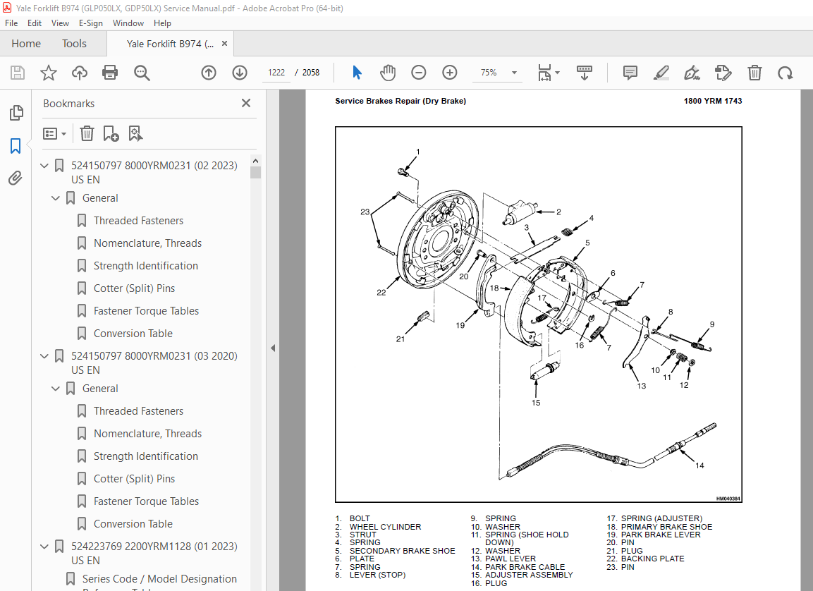
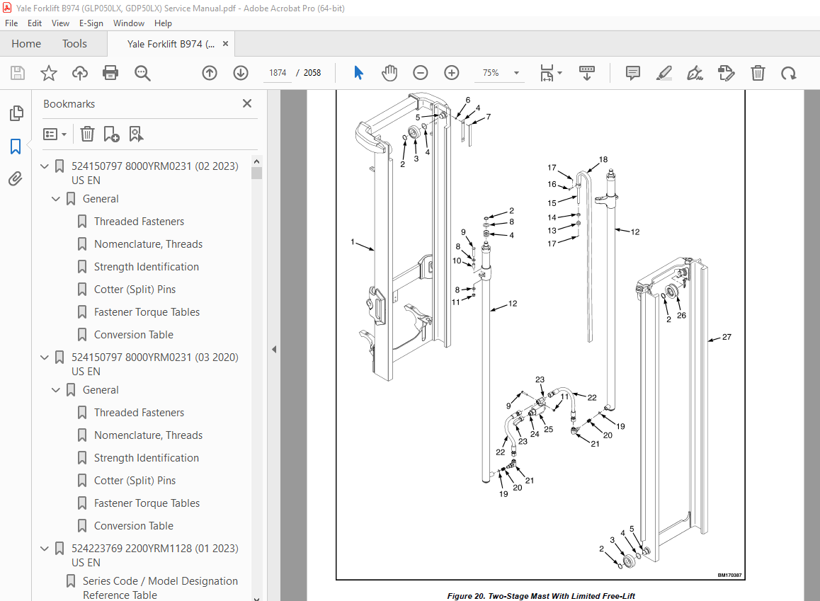
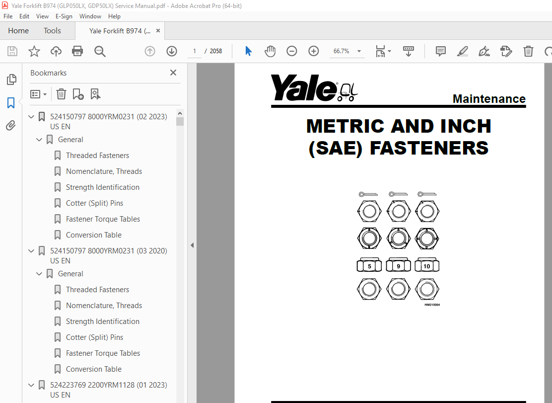
TABLE OF CONTENTS:
Yale Forklift B974 (GLP050LX, GDP50LX) Service Manual – PDF DOWNLOAD
524150797 8000YRM0231 (02 2023) US EN 1
General 7
Threaded Fasteners 7
Nomenclature, Threads 7
Strength Identification 8
Cotter (Split) Pins 9
Fastener Torque Tables 14
Conversion Table 16
524150797 8000YRM0231 (03 2020) US EN 23
General 27
Threaded Fasteners 27
Nomenclature, Threads 27
Strength Identification 28
Cotter (Split) Pins 29
Fastener Torque Tables 34
Conversion Table 36
524223769 2200YRM1128 (01 2023) US EN 43
Series Code / Model Designation Reference Table 51
General 53
Deutsch Crimping Tool 54
How to Strip a Wire for Use With Deutsch Crimping Tool 54
How to Crimp With the Deutsch Crimping Tool 55
Calibration Test for the Deutsch Crimping Tool 57
Deutsch Connectors 59
DT, DTM, and DTP Series Connectors 59
HD Series Connectors 102
Metri-Pack Connectors 124
Remove and Install 124
Micro-Pack Connectors 127
Weather-Pack Connectors 128
AMPSEAL Crimping Tools 130
AMP Hand Crimping Tool With Certi-Crimp 130
Description 130
Stripping Wire for Use with AMP Hand Crimping Tool 131
Insulation Crimp Adjustment 132
Maintenance and Inspection for AMP Hand Crimping Tool 132
AMP Hand Crimping Tool 132
Crimp Height Inspection 132
How to use AMP Hand Crimping Tool 133
AMP Pro-Crimper II Tool 133
Description 133
Remove and Install Die Set and Locator Assembly 134
Stripping Wire for Use With AMP PRO-CRIMPER II Tool 134
Contact Support Adjustment 135
Crimp Height Adjustment 136
Maintenance and Inspection Procedures 136
PRO-CRIMPER II Tool 136
Crimp Height Inspection 136
How to Use AMP PRO-CRIMPER II Tool 137
AMPSEAL Connector Assemblies 138
Description for Plug Connector Assembly 138
Seal Plug 139
Contact Crimping 139
Description for Plug Connector and Header Assembly 144
Voltage Reading 147
Seal Plug 147
Contact Crimping 147
AMP Superseal 1 5 Crimping Tools 154
Mini Mic Receptacle and Tab Contacts 154
Description 154
Crimping Conditions and Measurements 154
Insertion of Rubber Seal on Cable 156
AMP Hand Application Tool 161
Description 161
Maintenance and Inspection 161
Crimp Height Inspection 161
Crimp Height Adjustment 162
How to Use AMP Hand Application Tool 162
AMP Pro-Crimper II Tool 163
Description 163
Remove and Install Die Set and Locator Assembly 163
Adjustments 164
Contact Support 164
Crimp Height 165
Inspections and Maintenance 166
Crimp Height Inspection 166
Visual Inspection 166
Maintenance 167
How to Use Pro-Crimper II Tool 167
AMP Superseal 1 5 Connector Assemblies 168
Description 168
Repair and Maintenance 175
Panel Mount Option 175
AMP Fastin-Faston Hand Tools 176
Description – AMP Double Action Hand Tool 176
Maintenance and Inspection Procedures 176
Daily Maintenance 176
Periodic Tool Inspection 177
Lubrication 177
Visual Inspection 177
Crimp Height Inspection 177
Certi-Crimp Ratchet Inspection 178
How to Use AMP Double Action Hand Tool 179
Description – AMP Extraction Tool 180
Maintenance and Inspection 181
How to Use AMP Extraction Tool 181
AMP Fastin-Faston Receptacles and Housings 183
Description 183
Wire Repair 191
Wire Splicing Requirements 191
Deutsch Jiffy Splice 192
Twisted/Shielded Cable and Leads Repair 198
Special Tools 200
524223769 2200YRM1128 (07 2020) US EN 209
Series Code / Model Designation Reference Table 215
General 218
Deutsch Crimping Tool 218
How to Strip a Wire for Use With Deutsch Crimping Tool 218
How to Crimp With the Deutsch Crimping Tool 219
Calibration Test for the Deutsch Crimping Tool 221
Deutsch Connectors 223
DT, DTM, and DTP Series Connectors 223
HD Series Connectors 265
Metri-Pack Connectors 288
Remove and Install 288
Micro-Pack Connectors 290
Weather-Pack Connectors 291
AMPSEAL Crimping Tools 293
AMP Hand Crimping Tool With Certi-Crimp 293
Description 293
Stripping Wire for Use with AMP Hand Crimping Tool 293
Insulation Crimp Adjustment 294
Maintenance and Inspection for AMP Hand Crimping Tool 294
AMP Hand Crimping Tool 294
Crimp Height Inspection 294
How to use AMP Hand Crimping Tool 295
AMP Pro-Crimper II Tool 295
Description 295
Remove and Install Die Set and Locator Assembly 296
Stripping Wire for Use With AMP PRO-CRIMPER II Tool 297
Contact Support Adjustment 297
Crimp Height Adjustment 298
Maintenance and Inspection Procedures 298
PRO-CRIMPER II Tool 298
Crimp Height Inspection 298
How to Use AMP PRO-CRIMPER II Tool 299
AMPSEAL Connector Assemblies 300
Description for Plug Connector Assembly 300
Seal Plug 301
Contact Crimping 301
Description for Plug Connector and Header Assembly 306
Voltage Reading 308
Seal Plug 308
Contact Crimping 308
AMP Superseal 1 5 Crimping Tools 315
Mini Mic Receptacle and Tab Contacts 315
Description 315
Crimping Conditions and Measurements 315
Insertion of Rubber Seal on Cable 317
AMP Hand Application Tool 322
Description 322
Maintenance and Inspection 322
Crimp Height Inspection 322
Crimp Height Adjustment 323
How to Use AMP Hand Application Tool 323
AMP Pro-Crimper II Tool 324
Description 324
Remove and Install Die Set and Locator Assembly 325
Adjustments 325
Contact Support 325
Crimp Height 326
Inspections and Maintenance 327
Crimp Height Inspection 327
Visual Inspection 327
Maintenance 328
How to Use Pro-Crimper II Tool 328
AMP Superseal 1 5 Connector Assemblies 329
Description 329
Repair and Maintenance 336
Panel Mount Option 336
AMP Fastin-Faston Hand Tools 337
Description – AMP Double Action Hand Tool 337
Maintenance and Inspection Procedures 337
Daily Maintenance 337
Periodic Tool Inspection 338
Lubrication 338
Visual Inspection 338
Crimp Height Inspection 338
Certi-Crimp Ratchet Inspection 339
How to Use AMP Double Action Hand Tool 340
Description – AMP Extraction Tool 341
Maintenance and Inspection 341
How to Use AMP Extraction Tool 342
AMP Fastin-Faston Receptacles and Housings 343
Description 343
Wire Repair 350
Wire Splicing Requirements 350
Deutsch Jiffy Splice 351
Twisted/Shielded Cable and Leads Repair 356
Special Tools 359
524240453 0600YRM1205 (01 2017) US EN 367
General 373
Engine Identification 373
Major Engine Component Identification 373
Location of Labels 374
Engine Removal and Installation 375
Cylinder Head Assembly Repair 375
Glow Plugs 378
Remove 378
Install 378
Valve Cover 378
Remove 378
Clean and Inspect 379
Install 379
Rocker Arm Assembly 379
Remove 379
Disassemble 380
Clean and Inspect 381
Push Rods 381
Rocker Arm Assembly 381
Assemble 381
Install 382
Valve Clearance Adjustments 382
Cylinder Head Assembly 383
Remove 383
Disassemble 388
Valves and Valve Springs, Remove 388
Valve Guides, Remove 388
Clean and Inspect 389
Cylinder Head 389
Valve Guides 390
Valves 390
Valve Sink 390
Valve Seat 391
Valve Springs 391
Assemble 392
Valve Guides, Install 392
Valves and Valve Springs, Install 392
Install 393
Timing Gear Case and Timing Gears Repair 394
Timing Gear Case Cover 395
Remove 395
Clean and Inspect 395
Install 396
Timing Gears 396
Crankshaft Gear 397
Remove 397
Install 397
Idler Gear 397
Remove 397
Inspect 398
Install 398
Camshaft Gear 398
Remove 398
Install 399
Timing Gear Case 399
Remove 399
Clean and Inspect 400
Install 400
Drive Train, Camshaft, and Cylinder Block Repair 401
Remove 401
Disassemble 402
Pistons and Connecting Rods 402
Crankshaft 402
Camshaft 405
Clean and Inspect 406
Cylinder Block 406
Honing and Boring 409
Pistons 410
Piston Pin 410
Connecting Rod 411
Tappets 411
Crankshaft 412
Camshaft 413
Camshaft Bushing 414
Assemble 414
Camshaft 414
Crankshaft 414
Pistons and Connecting Rods 415
Install 416
Lubrication System Repair 417
Engine Oil and Oil Filter Change 417
Oil Pan 417
Remove 417
Install 418
Oil Suction Tube 418
Remove 418
Clean 419
Install 419
Oil Pump 419
Remove 419
Clean and Inspect 420
Outer Rotor Outside Clearance 420
Outer Rotor to Inner Rotor Tip Clearance 421
Outer Rotor Side Clearance 421
Rotor Shaft Clearance 421
Install 422
Fuel System Repair 422
Fuel Injectors 423
Remove 423
Inspect 424
Clean 424
Test 424
Install 427
Electronic Throttle System 427
Remove 427
Install 430
Inspect 431
Adjust 432
Manual Throttle System 433
Fuel Injection Pump 433
Remove 433
Clean and Inspect 437
Install 437
Check/Adjust Fuel Injection Timing 438
Cooling System Repair 440
V-Belt 440
Remove 440
Inspect 440
Install 440
Adjust 440
Water Pump 442
4TNE92-NMHA, 4TNE92-NMHA/580090035, 4TNE92-SNMU, and 4TNE98-SNMU Engines 442
Remove 442
Install 443
4TNE92-NMH, 4TNE98-NMH, 4TNE92-NMH/580090036, and 4TNE98-BNMH Engines 444
Remove 444
Install 445
Thermostat 447
Remove 447
Inspect 448
Install 448
Flywheel and Flywheel Housing 448
Flywheel 449
Remove 449
Install 450
Flywheel Housing 450
Remove 450
Install 450
Electrical Equipment Repair 452
Alternator 452
Remove 452
Bench Test 454
Regulate Voltage Check 454
No Load Test 456
Output Test 456
Install 456
Starter 457
Remove 458
No Load Test 458
Install 459
Engine Specifications 460
Engine Data 460
Engine Tuning 468
Cylinder Head 468
Intake/Exhaust Valve and Guide 469
Valve Spring 469
Rocker Arm and Shaft 469
Push Rod 470
Gear Train and Camshaft 470
Camshaft 470
Idle Gear Shaft and Bushing 470
Backlash of Each Gear 471
Cylinder Block 471
Crankshaft 471
Thrust Bearing 472
Piston 472
Piston Ring 472
Connecting Rod 473
Rod Small End 473
Tappet 473
Oil Pump 474
Engine Oil Pressure 474
Outer Rotor Outside Clearance 474
Outer Rotor Side Clearance 474
Outer Rotor to Inner Rotor Tip Clearance 474
Rotor Shaft Clearance 474
Standard Torque Specifications 475
Standard Torque Chart 475
Special Torque Specifications 476
Special Tools 477
550022929 9000YRM1434 (02 2018) US EN 485
SECTION 9010 Operational Diagnostic Procedures 491
Group 05 – Operational Checkout 493
SECTION 9020 Engine 503
Group 10 – Principles of Operation 507
Group 30 – Observed Symptoms 563
Group 40 – Tests and Adjustments 617
SECTION 9030 Electrical System 629
Group 03 – General Maintenance and Diagnostic Data 635
Group 10 – Principles of Operation 657
Group 20 – Diagnostic Trouble Codes 667
Group 30 – Observed Symptoms 853
SECTION 9040 Drive Train 889
Group 10 – Principles of Operation 891
Group 30 – Observed Symptoms 905
Group 40 – Tests and Adjustments 935
SECTION 9050 Hydraulic Systems 939
Group 10 – Principles of Operation 941
Group 33 – Observed Symptoms-Gear Pump 957
Group 43 – Tests and Adjustments-Gear Pump 991
SECTION 9060 Operators Station 1007
Group 10 – Principles of Operation 1009
SECTION 9070 Front End (Mast) and Chassis 1019
Group 10 – Principles of Operation 1021
Group 30 – Observed Symptoms 1031
SECTION 9080 Supplementary Data 1073
Group 50 – Abbreviations and Acronyms 1075
Group 60 – Special Tools List 1083
Group 70 – Fault Mode Indicator Reference 1085
Group 80 – Supplier Specification Data 1087
550073240 1900YRM1620 (01 2023) US EN 1091
Proper Flushing after Major Hydraulic Repairs 1097
Introduction 1097
The Phases of Wear 1097
Causes of Hydraulic System Failure 1097
Progression of Contaminant Caused Hydraulic System Failure 1098
Hydraulic System Flushing Techniques 1098
Double Oil and Filter Change 1098
Mechanical Cleaning 1099
Cleaning of Components 1099
How to Clean Tubes and Hoses 1099
Filter Caddy 1099
Start-Up Procedure for Cleaned System 1100
Contaminated Oil Coolers 1100
Additional Filter Caddy Functions 1101
How to Handle Different Fluids 1101
Water Removal Filters 1101
Fluid Conditioning and System Flushing Procedures 1102
Operation of the Filter Caddy 1102
Filter Caddy operation 1102
Fluid Conditioning Procedure 1102
Filter Caddy Start-Up 1103
System Flushing Procedure 1103
Component Cleaning Procedure 1104
Reservoir Cleaning Procedure 1104
Cylinder Cleaning Procedure 1104
Hose and Tube Cleaning Procedure 1104
Valve Cleaning Procedure 1105
Front-End Attachment Cleaning Procedure 1106
System Flushing Procedure 1106
Filter Caddy Start-Up 1107
System Start-Up and Flushing 1107
Reservoir Fluid Cleaning Times 1108
Dealing With Different Fluid Types 1109
Cleaning Procedure After Switching Fluids (Cross Contamination Flushing) 1109
Filter Caddy Maintenance 1109
Servicing the Strainer 1109
DC Motor 1109
Hydraulic Oil Sampling Method and Procedure 1110
Hydraulic Oil Sampling Method 1110
Objective 1110
General Guidelines 1110
Synopsis 1111
Hydraulic Oil Analysis Report Guidelines 1112
Sampling Conditions 1112
Equipment 1112
Sampling Procedure 1113
Hydraulic Oil Sampling 1113
Sample Labeling 1113
Results Documentation 1113
550073240 1900YRM1620 (03 2020) US EN 1115
Proper Flushing after Major Hydraulic Repairs 1119
Introduction 1119
The Phases of Wear 1119
Causes of Hydraulic System Failure 1119
Progression of Contaminant Caused Hydraulic System Failure 1120
Hydraulic System Flushing Techniques 1120
Double Oil and Filter Change 1120
Mechanical Cleaning 1121
Cleaning of Components 1121
How to Clean Tubes and Hoses 1121
Filter Caddy 1121
Start-Up Procedure for Cleaned System 1122
Contaminated Oil Coolers 1122
Additional Filter Caddy Functions 1122
How to Handle Different Fluids 1122
Water Removal Filters 1123
Fluid Conditioning and System Flushing Procedures 1123
Operation of the Filter Caddy 1123
Filter Caddy operation 1123
Fluid Conditioning Procedure 1124
Filter Caddy Start-Up 1124
System Flushing Procedure 1125
Component Cleaning Procedure 1125
Reservoir Cleaning Procedure 1125
Cylinder Cleaning Procedure 1125
Hose and Tube Cleaning Procedure 1126
Valve Cleaning Procedure 1126
Front-End Attachment Cleaning Procedure 1127
System Flushing Procedure 1127
Filter Caddy Start-Up 1128
System Start-Up and Flushing 1128
Reservoir Fluid Cleaning Times 1129
Dealing With Different Fluid Types 1129
Cleaning Procedure After Switching Fluids (Cross Contamination Flushing) 1129
Filter Caddy Maintenance 1130
Servicing the Strainer 1130
DC Motor 1130
Hydraulic Oil Sampling Method and Procedure 1130
Hydraulic Oil Sampling Method 1130
Objective 1130
General Guidelines 1130
Synopsis 1131
Hydraulic Oil Analysis Report Guidelines 1132
Sampling Conditions 1133
Equipment 1133
Sampling Procedure 1133
Hydraulic Oil Sampling 1133
Sample Labeling 1134
Results Documentation 1134
550108495 1300YRM1740 (06 2018) US EN 1137
General 1141
Serial Number 1141
Hydraulic Gear Pump 1141
Remove 1141
Install 1141
Housing Fittings Replacement 1142
Remove 1142
Install 1144
Charge Pump Repair 1144
Torque Converter Replacement 1147
Remove 1147
Clean and Inspect 1147
Install 1147
Stator Support Assembly Repair 1148
Remove 1148
Disassemble 1155
Clean 1156
Inspect 1156
Assemble 1157
Install 1157
Clutch Packs Repair 1159
Remove 1159
Disassemble 1161
Housings 1161
Clutch Packs 1164
Clean 1175
Inspect 1176
Assemble 1176
Clutch Packs 1176
Housings 1190
Install 1192
Drive Chains and Sprockets 1195
Remove 1195
Clean 1197
Inspect 1198
Install 1198
Proportional and Enable Solenoid Valves 1198
Proportional Valves 1198
Remove 1198
Disassemble 1200
Clean and Inspect 1201
Assemble 1201
Install 1201
Enable Solenoid Valve 1201
Remove 1201
Disassemble 1202
Clean and Inspect 1202
Assemble 1202
Install 1202
Pedal Repair Foot Directional Control 1203
Remove and Disassemble 1203
Clean and Inspect 1206
Assemble and Install 1207
550108498 1800YRM1743 (06 2018) US EN 1211
General 1215
Dry Brake System 1215
Wet Brake System 1215
Service Brakes Repair (Dry Brake) 1215
Remove and Disassemble 1216
Clean 1223
Inspect 1224
Assemble and Install 1224
Adjust 1232
Inching Overlap Adjustment 1232
Parking Brake Repair 1233
Remove and Disassemble 1233
Dry Brake System 1233
Wet Brake System 1235
Assemble and Install 1237
Dry Brake System 1237
Wet Brake System 1237
Adjust 1237
Master Cylinder Repair 1238
Remove (Dry Brake) 1238
Disassemble (Dry Brake) 1239
Clean and Inspect (Dry Brake) 1241
Assemble (Dry Brake) 1241
Bench Bleed Master Cylinder (Dry Brake) 1241
Install and Adjust (Dry Brake) 1241
Remove (Wet Brake) 1242
Disassemble (Wet Brake) 1243
Clean and Inspect (Wet Brake) 1244
Assemble (Wet Brake) 1245
Install and Adjust (Wet Brake) 1245
Service Brakes Adjustment (Dry Brake) 1246
Brake System Air Removal 1246
Using Pressure Bleed System 1246
Using Brake Pedal Pressure 1246
Brake Pedal Adjustment 1247
Free Pedal Adjustment 1248
Torque Specifications 1250
550108499 1900YRM1744 (06 2018) US EN 1253
General 1257
Hydraulic Gear Pump Assembly Repair 1258
Remove 1258
Disassemble 1262
Clean 1264
Inspect 1264
Assemble 1264
Install 1264
Quick-Lok™ Hydraulic Hose 1266
Hydraulic Gear Pump Specifications 1267
Variable Displacement Pump Repair 1269
Remove 1269
Disassemble 1274
Clean 1276
Inspect 1276
Assemble 1276
Install 1276
Variable Displacement Pump Checks and Adjustments 1279
Margin Pressure Check 1279
Flow Compensator Adjustment 1280
Pressure Compensator Adjustment 1280
Variable Displacement Pump Specifications 1281
Torque Specifications 1281
Hydraulic Gear Pump 1282
Variable Displacement Pump 1282
550108500 2000YRM1745 (06 2018) US EN 1285
General 1289
Electro-Hydraulic Main Control Valve 1289
Description 1289
Remove 1292
Electro-Hydraulic Control Valve Sections 1295
General 1295
Outlet Control Valve Section 1295
Remove 1295
Disassemble 1295
Clean 1297
Inspect 1297
Assemble 1297
Install 1298
Auxiliary Control Valve Sections 1298
Remove 1298
Disassemble 1300
Clean 1301
Inspect 1301
Assemble 1301
Install 1301
Tilt Control Valve Section 1302
Remove 1302
Disassemble 1302
Clean 1303
Inspect 1303
Assemble 1304
Install 1304
Lift/Lower Control Valve Section 1304
Remove 1304
Disassemble 1304
Clean 1306
Inspect 1306
Assemble 1307
Install 1307
Install 1307
Electro Hydraulic Poppet Valve (EHPV) Pilot Pin Adjustment 1310
Lift Pilot Pin 1310
Lower Pilot Pin 1312
Abnormal/Erroneous EHPV Adjustment 1314
Manual Main Control Valve 1314
Description 1314
Remove 1317
OPS Solenoid Assembly 1323
General 1323
Remove 1324
Clean and Inspect 1326
Install 1326
Manual Control Valve Sections 1327
General 1327
Outlet Control Valve Section 1327
Remove 1327
Disassemble 1327
Clean 1330
Inspect 1330
Assemble 1330
Install 1331
Auxiliary Control Valve Sections 1331
Remove 1331
Disassemble 1331
Clean 1334
Inspect 1334
Assemble 1334
Install 1334
Lift/Tilt Control Valve Section 1335
Remove 1335
Disassemble 1335
Clean 1340
Inspect 1340
Assemble 1340
Install 1341
Install 1341
Pressure Relief Valve Check and Adjustment 1345
Primary Relief Valve 1346
Secondary Relief Valve 1347
Steering Control Unit Repair 1351
Steering Control Unit, Remove 1351
Steering Control Unit, Disassemble 1353
Steering Control Unit, Clean 1355
Steering Control Unit, Inspect 1355
Steering Control Unit, Assemble 1355
Relief Valve, Disassemble 1356
Relief Valve, Clean 1356
Relief Valve, Inspect 1357
Relief Valve, Assemble 1357
Steering Control Unit, Install 1357
550108890 0600YRM1755 (04 2019) US EN 1361
General 1367
Engine Removal and Installation 1370
Cylinder Head Assembly Repair 1370
Drive Train and Lubrication System 1409
Remove 1410
Disassemble 1410
Oil Pan 1410
Oil Pump (Front Cover) 1413
Clean and Inspect 1414
Front Case 1414
Oil Seal 1414
Counterbalance Shaft 1414
Oil Pump 1414
Assemble 1415
Counterbalance Shaft Bearings 1415
Oil Pump (Front Cover) 1416
Oil Pan 1418
Install 1418
Crankshaft and Cylinder Block Repair 1419
Remove Major Attaching Components 1419
Crankshaft and Cylinder Block 1419
Remove 1419
Clean and Inspect 1420
Boring Cylinder 1421
Install 1422
Piston and Connecting Rod 1424
Remove 1424
Disassemble 1425
Clean and Inspect 1426
Assemble 1427
Install 1429
Piston 1429
Rod Bearing 1430
Install Major Attaching Components 1431
Fuel System Repair 1431
Cooling System Repair 1431
Electrical Equipment Repair 1432
Flywheel and Flywheel Housing 1432
Flywheel 1432
Remove 1432
Install 1433
Flywheel Housing 1434
Remove 1434
Install 1434
Engine Specifications 1434
Engine Data 1434
Engine Tuning 1436
Cylinder Head 1436
Intake/Exhaust Valve and Guide 1436
Valve Spring 1437
Gear Train and Camshaft 1437
Camshaft 1437
Idle Gear Shaft and Bushing 1437
Cylinder Block 1437
Crankshaft 1437
Piston 1438
Piston Ring 1438
Connecting Rod 1438
Oil Pump 1438
Engine Oil Pressure 1438
Drive Gear Clearance 1438
Driven Gear Clearance 1439
Torque Specifications 1439
Special Tools 1440
550108890 0600YRM1755 (08 2023) US EN 1447
General 1455
Engine Removal and Installation 1459
Cylinder Head Assembly Repair 1460
Drive Train and Lubrication System 1501
Remove 1501
Disassemble 1501
Oil Pan 1501
Oil Pump (Front Cover) 1504
Clean and Inspect 1505
Front Case 1505
Oil Seal 1505
Counterbalance Shaft 1505
Oil Pump 1505
Assemble 1506
Counterbalance Shaft Bearings 1506
Oil Pump (Front Cover) 1507
Oil Pan 1509
Install 1509
Crankshaft and Cylinder Block Repair 1511
Remove Major Attaching Components 1511
Crankshaft and Cylinder Block 1511
Remove 1511
Clean and Inspect 1512
Boring Cylinder 1513
Install 1514
Piston and Connecting Rod 1516
Remove 1516
Disassemble 1517
Clean and Inspect 1517
Assemble 1518
Install 1520
Piston 1520
Rod Bearing 1521
Install Major Attaching Components 1522
Fuel System Repair 1523
Cooling System Repair 1524
Electrical Equipment Repair 1525
Flywheel and Flywheel Housing 1526
Flywheel 1526
Remove 1526
Install 1527
Flywheel Housing 1527
Remove 1527
Install 1527
POWER TAKE OFF (PTO), REMOVE AND INSTALL 1528
REMOVE COVER 1528
INSTALL COVER 1528
Engine Specifications 1530
Engine Data 1530
Engine Tuning 1531
Cylinder Head 1532
Intake/Exhaust Valve and Guide 1532
Valve Spring 1532
Gear Train and Camshaft 1533
Camshaft 1533
Idle Gear Shaft and Bushing 1533
Cylinder Block 1533
Crankshaft 1533
Piston 1533
Piston Ring 1534
Connecting Rod 1534
Oil Pump 1534
Engine Oil Pressure 1534
Drive Gear Clearance 1534
Driven Gear Clearance 1534
Torque Specifications 1535
Special Tools 1537
550108892 0900YRM1757 (06 2018) US EN 1541
General 1547
Intake-Air System 1548
Intake-Air System Manifold Vacuum Check 1548
Throttle Body 1548
Remove 1549
Install 1550
Intake Manifold 1550
LPG Tank and Bracket Replacement Lift Truck Models GLC20-35VX (GLC040-070VX, GLC055SVX) (C910) and GLP20-35VX (GLP040-070VX) (D875) 1550
Remove LPG Tank 1550
Install LPG Tank 1553
Remove LPG Bracket 1553
Install LPG Bracket 1556
Remove LPG Tank Bracket Alignment Pin 1556
Install LPG Tank Bracket Alignment Pin 1558
LPG Tank and Bracket Replacement Lift Truck Models GLC050LX, GLC050LX2 (B967) and GLP20-25LX (GLP050LX) (B974) 1559
Remove LPG Tank 1559
LPG Tank Install 1561
Remove LPG Bracket 1561
Install LPG Bracket 1561
LPG Fuel Filter Unit Repair Lift Truck Models GLC20-35VX (GLC040-070VX, GLC055SVX) (C910) and GLP20-35VX (GLP040-070VX) (D875) 1562
Fuel Filter Element 1562
Remove 1562
Clean/Inspect 1562
Install 1563
Fuel Filter Housing 1563
Remove 1563
Disassemble 1564
Assemble 1565
Install 1565
LPG Fuel Filter Unit Repair Lift Truck Models GLC050LX, GLC050LX2 (B967) and GLP/GDP20-25LX (GLP/GDP050LX) (B974) 1566
Fuel Filter Element 1566
Remove 1566
Clean/Inspect 1567
Install 1567
Fuel Filter Housing 1567
Remove 1567
Disassemble 1567
Assemble 1568
Install 1568
Electronic Throttle Body Repair 1568
Remove 1569
Install 1570
LPG Fuel Mixer With Direct Electronic Pressure Regulator (DEPR) Repair 1571
Remove 1572
Install 1574
Gasoline Fuel System 1575
Before Repair Procedure 1576
Fuel Line Safety Procedure 1576
After Repair Procedure 1578
Fuel Hose, Install 1578
Fuel Leakage Check 1578
Fuel Line Pressure Check 1579
Fuel Injectors 1579
Remove 1579
Install 1580
Pressure Regulator 1580
Remove 1580
Install 1581
Control System 1581
Engine Control Module (ECM) 1581
Remove 1581
Install 1583
Fuel Level Sensor 1583
Remove 1583
Install 1583
Low LPG Pressure Switch 1584
Remove 1584
Install 1584
LPG Low Level Sensor 1584
Remove 1585
Install 1585
LPG Converter 1586
LPG Lock-Off Valve 1591
Remove 1591
Install 1592
Exhaust System 1594
Counterweight Exhaust System 1594
Remove and Disassemble 1594
Inspect 1595
Assemble and Install 1596
Overhead Exhaust System 1596
Remove and Disassemble 1596
Inspect 1598
Assemble and Install 1598
Exhaust Manifold 1598
Positive Crankcase Ventilation (PCV) Valve 1598
Remove 1598
Inspect 1598
Install 1599
Oxygen Sensor 1599
Remove 1599
Install 1600
LPG Fuel Testing 1600
General 1600
Available Fuel Tests 1601
Composition Test (ASTM D-2163) 1601
Ammonia Test (ASTM D-4490) 1601
Basic Nitrogen Test (ASTM UOP269-90) 1601
Residues Test (ASTM D-2158) 1601
Vapor Pressure Test (ASTM D-2598) 1601
Sulfur Compounds Test (ASTM D-5623) 1601
Methanol Test (ASTM D-4864) 1601
Copper Corrosion (ASTM D-1838) 1601
Where To Send LPG Fuel Samples For Testing 1601
Technical Data 1602
550109110 0100YRM1766 (06 2018) US EN 1605
General 1609
Hood, Seat, and Side Covers Replacement 1611
Remove 1611
Install 1618
Steering Column 1619
Description 1620
Steering Column Repair 1620
Remove 1620
Disassemble 1621
Clean 1622
Inspect 1623
Assemble 1623
Install 1623
Counterweight Replacement 1623
Remove 1623
Install 1625
Overhead Guard Replacement 1625
Remove 1626
Install 1626
Rain Top (Optional) 1627
Remove 1627
Clean and Inspect 1628
Install 1628
Operator Restraint System Replacement 1629
Description 1629
Emergency Locking Retractor (ELR) 1629
Engine Replacement 1630
Remove 1630
LPG Engine 1630
Diesel Engine 1638
Install 1644
LPG Engine 1644
Diesel Engine 1645
Transmission Replacement 1646
Remove 1646
Install 1648
Throttle Pedal and Cable Adjustment 1648
PSI 2 4L Engine 1648
Throttle Pedal Stop Adjustment 1648
Yanmar Diesel Engine 1649
Yanmar Diesel Engine With Electronic Throttle 1650
Exhaust System Repair 1651
Lift Trucks With Counterweight Exhaust System 1651
PSI Engines 1651
Yanmar Diesel Engine 1651
Remove and Disassemble 1651
Inspect 1651
Assemble and Install 1651
Lift Trucks With Overhead Exhaust System 1653
PSI Engines 1653
Yanmar Diesel Engine 1653
Remove and Disassemble 1653
Inspect 1653
Assemble and Install 1653
Cooling System 1656
Description 1656
Hydraulic Filter Repair 1656
Remove 1656
Clean and Inspect 1657
Install 1657
Tank Repair 1657
Hydraulic and Diesel Tanks 1657
Inspect 1657
Clean 1658
Steam Method of Cleaning 1659
Chemical Solution Method of Cleaning 1659
Additional Preparations for Repair 1660
Small Leaks, Repair 1660
Large Leaks, Repair 1660
Preparations for Use After Repair 1660
Label Replacement 1660
550109111 0700YRM1767 (06 2018) US EN 1667
General 1671
Cooling System Checks 1671
Exhaust Leaks Into Cooling System 1671
Water Flow Restrictions in Radiator 1671
Radiator Hoses 1671
Water Pump 1671
Flushing the Cooling System 1672
Cooling System, Clean 1672
Radiator Replacement 1672
Radiator, Remove 1673
Radiator, Install 1676
Fan Assembly Replacement 1677
Fan Removal 1677
Inspect 1680
Fan Installation 1680
550109112 1400YRM1768 (06 2018) US EN 1683
General 1687
Identification Plate 1687
Drive Axle Repair 1687
Remove and Disassemble 1687
Clean and Inspect 1691
Assemble and Install 1691
Differential Repair 1694
Remove 1694
Disassemble 1702
Clean and Inspect 1708
Assemble 1709
Install 1718
Pinion Inner Shim Set, Adjust Thickness (Depth of Pinion) 1718
Hypoid Gear Backlash, Adjust 1728
Hypoid Gear, Runout Check 1729
Gear Set, Tooth Contact Pattern Check 1730
Torque Specifications 1733
550109113 1600YRM1769 (06 2018) US EN 1737
General 1741
Steering Axle Assembly Repair 1741
Remove 1742
Disassemble 1742
Clean 1744
Inspect 1745
Assemble 1745
Install 1746
Spindles, Bearings, and Tie Rods Repair 1748
Spindles and Bearings 1748
Remove 1748
Disassemble 1749
Clean 1749
Inspect 1750
Assemble 1750
Install 1750
Tie Rods 1751
Remove 1751
Disassemble 1751
Clean 1752
Inspect 1752
Assemble 1752
Install 1752
Steering Cylinder Repair 1752
Remove 1753
Disassemble 1753
Clean 1754
Inspect 1754
Assemble 1755
Install 1755
Torque Specifications 1755
550109114 2100YRM1770 (06 2018) US EN 1759
General 1763
Description 1765
Safety Procedures When Working Near Mast 1766
Tilt Cylinder Repair 1767
Remove 1767
Disassemble 1768
Inspect 1769
Clean 1769
Assemble 1769
Install 1770
Tilt Cylinders, Adjust 1770
Tilt Cylinder Leak Check 1771
Torque Specifications 1772
Lift Cylinder Repair 1773
Main Lift Cylinders 1773
Remove 1773
Disassemble 1774
Clean 1775
Inspect 1776
Assemble 1776
Install 1776
System Air Bleed Procedures 1777
Three-Stage FFL Left Side Main Lift Cylinder 1777
Disassemble 1777
Clean 1779
Inspect 1779
Assemble 1779
Install 1779
Free-Lift Cylinder 1779
Remove 1779
Disassemble 1780
Clean 1780
Inspect 1781
Assemble 1781
Install 1781
Torque Specifications 1782
Lift Cylinder Leak Check 1782
Integral Sideshift Cylinder Repair 1782
Before December 2016 1782
Remove 1782
Disassemble 1783
Clean 1784
Inspect 1784
Assemble 1784
Install 1785
After December 2016 1785
Remove 1785
Disassemble 1785
Clean 1786
Inspect 1786
Assemble 1786
Install 1787
Integral Sideshift Cylinder Gland Leak Checks 1787
Seal Kit Installation 1788
External Installation (Seal and Back-Up Ring) 1788
Internal Installation (Piston Rod Assembly) 1788
550109115 2200YRM1771 (06 2018) US EN 1791
General 1795
Engine Control Module (ECM), Yanmar Diesel Engine 1795
Remove 1795
Install 1796
Display Switch Cluster 1797
Remove 1797
Install 1799
Direction Control Lever 1799
Remove 1799
Install 1800
Key Switch 1800
Remove 1800
Install 1801
Display Switch Cluster Panel Bezel and Overlay 1801
Remove 1801
Install 1801
Steering Column Repair 1801
Remove 1802
Disassemble 1803
Assemble 1803
Install 1804
Sensors and Switches 1804
General 1804
Dash Panel, Kick Panel, and Seal Plate, Remove and Install 1804
Remove 1804
Install 1805
Accelerator Pedal Position Sensor 1805
Remove 1805
Install 1807
Brake Fluid Level Switch 1807
Remove 1807
Install 1808
Brake Pedal Position Sensor 1809
Remove 1809
Install 1810
Parking Brake Position Sensor 1810
Remove 1810
Install 1810
Seat Sensor (Operator Presence System) 1811
Non-Suspension Seat 1811
Remove 1811
Install 1812
Full Suspension Seats 1812
Remove 1812
Install 1812
Transmission Pressure Sensors (Transducers) 1813
Remove 1813
Install 1813
Transmission Temperature Sensor 1813
Remove 1813
Install 1814
Rear Horn Button Switch 1814
Remove 1814
Install 1814
Engine and Fuel Sensors and Switches, PSI 2 4L Dual Fuel Trucks 1815
Engine and Fuel Sensors, Yanmar 2 6L Diesel Trucks 1815
Engine Speed Sensor 1815
Remove 1815
Install 1816
Oil Pressure Sensor 1816
Remove 1816
Install 1816
Engine Coolant Temperature (ECT) Sensor 1817
Remove 1817
Install 1817
Fuel/Water Separator Sensor 1817
Remove 1817
Install 1817
Glow Plug Relay 1818
Remove 1818
Install 1820
Power Distribution Module (PDM) and Component Parts 1820
Power Distribution Module (PDM) as a Unit 1820
Remove 1820
Install 1821
Power Distribution Module (PDM) Components 1822
Remove and Install 1822
Battery 1822
Remove 1822
Install 1822
Lights 1823
Work Lights (Front and Rear) 1823
Remove 1823
Install 1823
Strobe Light 1823
Remove 1824
Install 1824
LED Tail, Backup, and Brake Lights 1824
Remove 1824
Install 1825
Reflectors 1825
Remove 1825
Install 1825
550109116 2200YRM1772 (06 2018) US EN 1829
General 1833
Ignition System 1833
Ignition Timing Adjustment 1833
Spark Plugs Check 1833
Coil Replacement 1833
Remove 1833
Inspect 1835
Install 1835
Starter Repair 1836
General 1836
Remove 1837
No-Load Test 1838
Magnetic Switch Test 1839
Pull-Out Test 1839
Holding Coil Test 1839
Return Test 1839
Pinion Movement Inspection 1840
Install 1840
Alternator Repair 1841
General 1841
Charging System Inspection 1841
Output Current Check 1842
No-Load Adjusted Voltage Check 1842
Remove 1843
Install 1843
Engine Sensors and Switches 1843
Oil Pressure Sensor 1844
Remove 1844
Install 1844
Air Filter Restriction Switch 1844
Remove 1844
Install 1844
Cam Angle Sensor 1845
Remove 1845
Install 1845
Crankshaft Position Sensor (CKP) 1845
Remove 1845
Install 1845
Temperature Manifold Absolute Pressure (TMAP) Sensor 1846
Remove 1846
Install 1847
Engine Coolant Temperature (ECT) Sensor 1847
Remove 1847
Install 1847
Electronic Control Module 1847
550109117 4000YRM1773 (06 2018) US EN 1851
General 1855
Safety Procedures When Working Near Mast 1855
Forks Replacement 1857
Remove 1857
Install 1858
Checks 1858
Adjustment 1859
Carriage Repair 1859
Standard Carriage 1860
Remove 1860
Clean and Inspect 1861
Install 1862
Integral Sideshift Carriage Prior to December, 2016 1863
Remove 1863
Disassemble 1865
Clean and Inspect 1865
Assemble 1866
Install 1866
Integral Sideshift Carriage After December, 2016 1867
Remove 1867
Disassemble 1870
Clean and Inspect 1870
Assemble 1870
Install 1871
Disconnecting Attachment Hydraulic Quick Disconnect Hoses 1872
Connecting Attachment Hydraulic Quick Disconnect Hoses 1872
Two-Stage Mast With Limited Free-Lift Repair 1872
Mast 1872
Remove 1872
Disassemble 1873
Clean and Inspect 1876
Assemble 1876
Install 1877
Header Hoses, Installation and Adjustment 1878
Install 1878
Adjustment 1883
Three-Stage Mast With Full Free-Lift Repair 1883
Remove 1883
Disassemble 1884
Clean and Inspect 1890
Assemble 1891
Install 1892
Header Hose Installation and Adjustment 1893
Standard 1893
Install 1893
Adjust 1898
Optional Equipment, Lift Truck GLP/GDP050LX (B974) 1899
Install 1899
Adjust 1908
Main Lift Cylinder Repair 1908
Lift and Tilt System Leak Check 1908
Tilt Cylinders Adjustment 1908
Lift Chain Adjustment 1908
Mast Adjustments 1909
Load Roller Adjustment 1910
Mast Side Kicking Adjustment 1912
Carriage Adjustment 1913
550109118 8000YRM1774 (10 2019) US EN 1917
General 1923
Serial Number Data 1923
How to Move Disabled Lift Truck 1923
How to Tow Lift Truck 1923
How to Put Lift Truck on Blocks 1924
How to Raise Drive Tires 1924
How to Raise Steering Tires 1925
How to Clean a Lift Truck 1925
Maintenance Schedule 1926
Maintenance Procedures Every 8 Hours or Daily 1936
How to Make Checks With Engine Stopped 1936
Tires and Wheels 1936
Safety Labels 1937
Mast, Carriage, Lift Chains, Header Hoses, Attachment 1937
Operator Restraint System 1938
Emergency Locking Retractor (ELR) 1939
Hood and Seat Latches 1940
Engine Compartment 1940
Ground Static Strap 1940
Fuel, Oil, and Coolant Leaks, Check 1941
Hydraulic Hoses 1941
Coolant Hoses 1941
Steering Column Gas Cylinder 1941
Transmission 1941
Hydraulic System Oil 1942
Engine Oil 1942
Air Filter 1944
Forks 1944
Inspect 1944
Remove 1946
Install 1946
Adjust 1946
How To Make Checks With Engine Running 1947
Indicator Lights, Horn, Fuses, and Relays 1947
Service Brakes 1950
Brake Fluid Level 1950
Operation, Check 1950
Parking Brake 1950
Engine Oil Pressure 1950
Cooling System 1950
Steering System 1951
Control Levers and Pedals 1951
Lift System, Operate 1952
First Service After First 100 Hours of Operation 1952
PSI Engine Oil and Oil Filter Change 1952
Yanmar Engine Oil and Oil Filter Change 1953
Maintenance Procedures Every 250 Hours or 6 Months 1953
PSI 2 4L Engine Oil and Oil Filter Change 1953
Drain Oil from LPG Vaporizer Regulator (LPG Converter) 1954
Maintenance Procedures Every 500 Hours or 6 Months 1955
Hydraulic System Oil 1956
Hydraulic Tank Breather 1957
Inspect 1957
Battery 1957
Yanmar 2 6L Engine Oil and Oil Filter Change 1957
Yanmar 2 6L Engine Drive Belt 1957
Clean Debris From Radiator Core 1958
Transmission Oil Level 1959
Forks 1959
Inspect 1959
Mast Lubrication 1960
Header Hose Checks 1963
Lift Chain Lubrication 1963
Tilt Cylinder Lubrication 1963
Master Cylinder Rod End Pin Lubrication 1964
Manual Hydraulic Levers Lubrication 1965
Brake Fluid 1965
Parking Brake Adjustment 1965
Tie Rod Lubrication 1966
Differential and Drive Axle Oil 1966
Maintenance Procedures Every 1000 Hours or 6 Months 1967
Drive Belt Check, PSI 2 4L Engine 1967
LPG Fuel Filter Replace – PSI 2 4L LPG Engine 1967
Remove 1967
Clean/Inspect 1968
Install 1968
In-Line Fuel Filter Replacement – PSI 2 4L Dual Fuel Engine 1969
Fuel Filter Replacement – Yanmar 2 6L Engine 1969
Priming the Fuel System (Yanmar) 1971
Lift Chains Wear Check 1971
Lift Chain Lubrication 1972
Integral Sideshift Carriage, Check Bearings 1972
Steering Axle 1973
Control Levers and Pedals 1973
Maintenance Procedures Every 2000 Hours or 1 Year 1973
Hydraulic System 1974
Hydraulic Oil Filter Element, Replace 1974
Remove 1974
Clean and Inspect 1974
Install 1974
Hydraulic Tank Breather, Replace 1975
Air Filter 1976
Oxygen Sensor 1978
Ignition System – PSI Engine 1979
Forks, Inspect 1979
Fuel Injector, Yanmar Engines 1981
Integral Sideshift Carriage 1981
Bearings, Replace 1981
Transmission Oil and Oil Filter, Replace 1981
Remove 1981
Clean and Inspect 1982
Install 1982
Brake Fluid Change 1982
Service Brakes 1984
Drive Axle and Differential Oil, Change 1984
Wheel Bearings 1986
Steer Wheels, Lubrication 1986
Maintenance Procedures Every 4000 Hours or 2 Years 1986
Hydraulic Oil, Change 1986
Cooling System 1988
Maintenance Procedures Every 6000 Hours 1989
Timing Belt Change, PSI Engine 1989
Safety Procedures When Working Near Mast 1990
Hood Latch Check 1992
Lift Chain Adjustments 1993
Jump-Starting the Lift Truck 1995
Jump-Starting Using a Battery Charger 1995
Jump-Starting a Lift Truck Using Another Lift Truck 1995
Welding Repairs 1995
Overhead Guard Changes 1996
Wheels and Tires Replacement 1996
General 1996
How to Change Solid Rubber Tire (GC Series) 1996
Remove and Install Tire on Wheel 1996
Pneumatic Tire With Tube, Repair 1997
Remove Wheels From Lift Truck 1997
Remove Tire From Wheel 1998
Install Wheel in Tire 2001
Add Air to Pneumatic Tires With Tube 2003
Wheels, Install 2004
Pneumatic Tubeless Tire, Repair 2004
Remove Wheels From Lift Truck 2004
Add Air to Pneumatic Tubeless Tire 2009
Wheels, Install 2009
Solid Rubber Tires on Pneumatic Wheels, Change 2010
Adhesives and Sealants 2013
550109119 8000YRM1775 (09 2019) US EN 2015
Lift Truck Lifting Capacity 2019
Counterweight Weights 2019
Tire Sizes 2019
Capacities 2019
Electrical System 2022
Transmission Oil Pressures 2023
Hydraulic System Relief Pressures 2023
Steering System 2024
Stall Speeds 2024
Mast Speeds 2024
Tilt Angles 2025
Front End Equipment 2026
Mast Creep 2026
Engine Specifications 2026
Torque Specifications 2027
Frame 2027
Mast 2027
Steering System 2027
Drive Axle 2027
Transmission 2028
Engine – PSI 2 4L LPG and Dual Fuel 2028
Engine – Yanmar 2 6L Diesel 2029
550109120 8000YRM1776 (12 2019) US EN 2033
Diagrams and Schematics 2037
More products