$41.95
Yale Forklift C813 (GDP070-090LJ; GDP100-120MJ) Service Manual PDF
Yale Forklift C813 (GDP070-090LJ; GDP100-120MJ) Service Manual – PDF DOWNLOAD
FILE DETAILS:
Yale Forklift C813 (GDP070-090LJ; GDP100-120MJ) Service Manual – PDF DOWNLOAD
Language : English
Pages : 1140
Downloadable : Yes
File Type : PDF
PART NO. 524150774
IMAGES PREVIEW OF THE MANUAL:
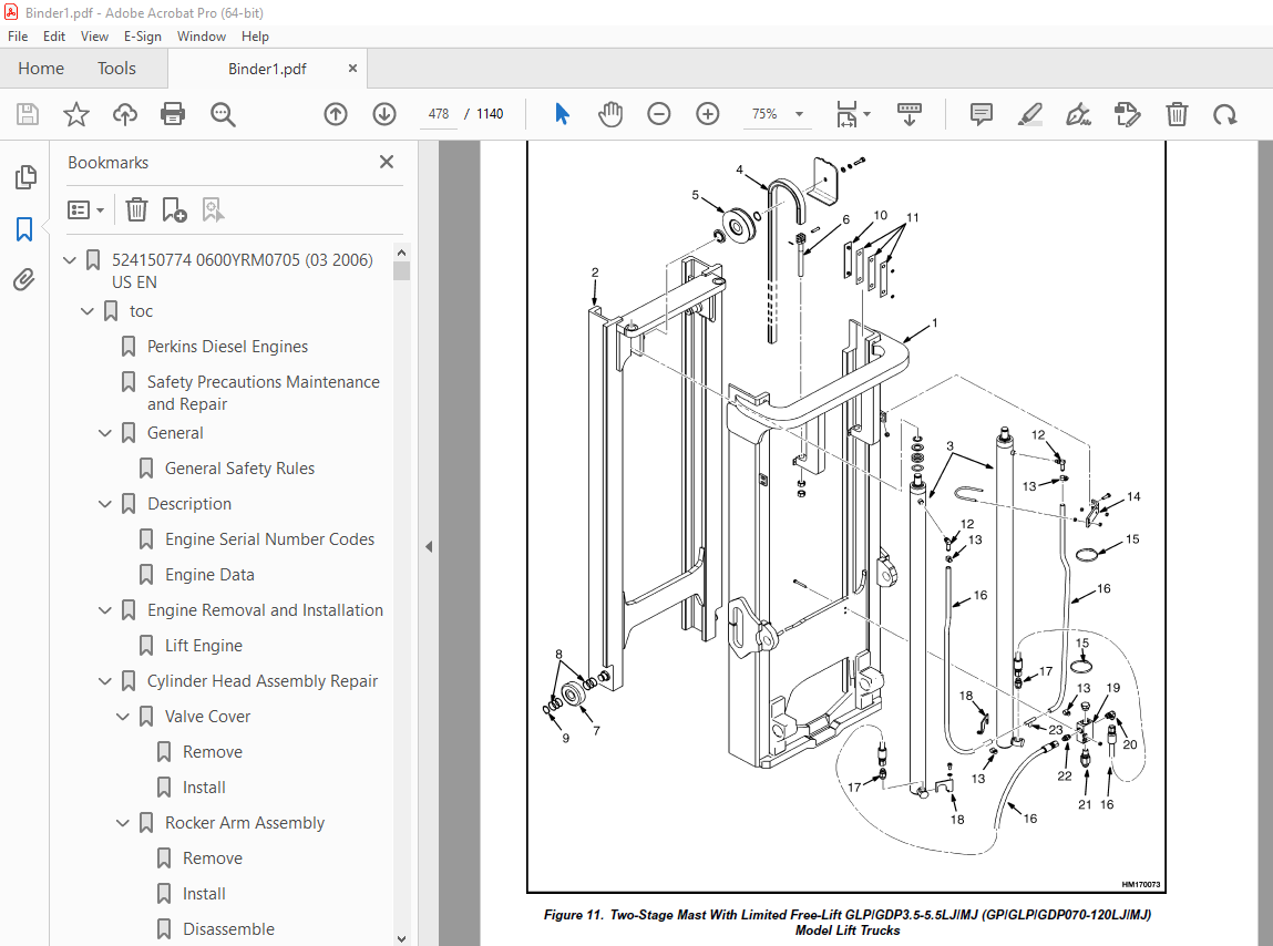
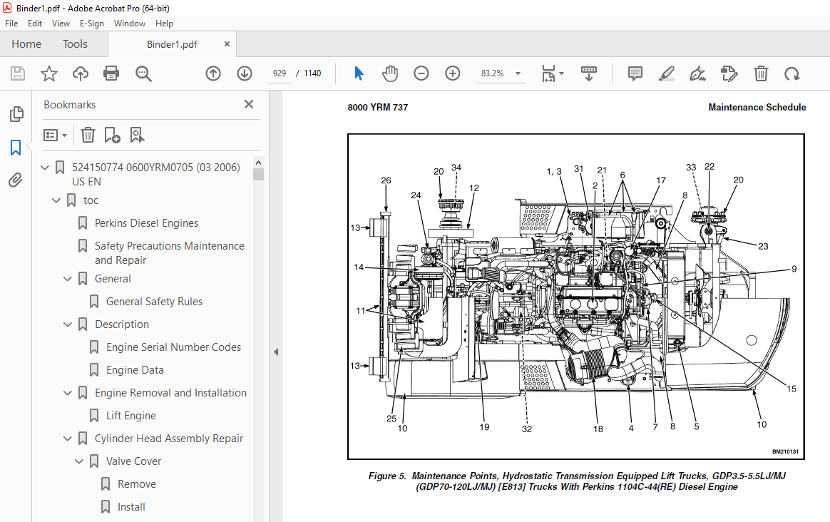
TABLE OF CONTENTS:
Yale Forklift C813 (GDP070-090LJ; GDP100-120MJ) Service Manual – PDF DOWNLOAD
524150774 0600YRM0705 (03 2006) US EN 1
toc 1
Perkins Diesel Engines 1
Safety Precautions Maintenance and Repair 2
General 9
General Safety Rules 9
Description 10
Engine Serial Number Codes 13
Engine Data 13
Engine Removal and Installation 15
Lift Engine 15
Cylinder Head Assembly Repair 15
Valve Cover 15
Remove 15
Install 16
Rocker Arm Assembly 16
Remove 16
Install 16
Disassemble 16
Inspect 17
Assemble 17
Valve Clearance Adjustments 17
Four-Cylinder Engines 18
Six-Cylinder Engines 18
Valve Springs 18
Cylinder Head Assembly 20
Remove 20
Install 22
Valves and Valve Springs 26
Remove 26
Inspect 26
Install 27
Valve Guides 27
Inspect 27
Remove 28
Install 28
Cylinder Head and Valve Seats 28
Inspect 28
Repair 28
New Valve Seats, Install 28
Piston and Connecting Rod Assemblies Repair 30
Rod Bearings 30
Remove 31
Install 31
Piston and Connecting Rod Assembly 32
Service Note 32
Remove 32
Install 33
Piston Rings 34
Remove 34
Inspect 34
Install 34
Piston and Connecting Rod 35
Disassemble 35
Inspect 36
How to Select Correct Replacements 36
Install 37
Piston Cooling Jets 37
Remove 37
Install 38
Crankshaft Assembly Repair 38
General 38
Crankshaft Pulley 39
Engine AR, Remove 39
Engines YG and YH, Remove 39
Inspect 40
Engine AR, Install 40
Engines YG and YH, Install 40
Rear Oil Seal 41
Replace 41
Main Bearings 42
Remove 42
Inspect 43
Install 43
Thrust Washers 43
Crankshaft Axial Movement, Check 43
Remove 44
Install 44
Crankshaft 45
Remove 45
Inspect 45
Install 45
Flywheel 47
Remove 47
Ring Gear, Replace 47
Install 47
Flywheel Housing 48
Remove 48
Install 48
Timing Case and Timing Gears Repair 49
General 49
Timing Case Cover 49
Remove 49
Install 50
Front Oil Seal 50
Remove 50
Install 50
Crankshaft Pulley Wear Sleeve 51
Install 51
Idler Gear and Hub 51
Remove 51
Install 52
Air Compressor Drive, Bendix 53
Disassemble 53
Assemble 54
Fuel Injection Pump Gear 54
Remove 55
Install 55
Camshaft Gear 56
Remove 56
Install 56
Crankshaft Gear 57
Remove 57
Install 57
Timing Case 57
Remove 57
Install 58
Camshaft and Tappets 59
Remove 59
Install 59
Cylinder Block Assembly Repair 60
Description 60
Cylinder Block 60
Disassemble 60
Inspect 61
Assemble 61
Cylinder Bore (Four-Cylinder Engines) 61
Cylinder Liner (Six-Cylinder Engines) 62
Inspect 62
Cylinder Liner Condition, Check 62
Remove 63
Service Liner, Install 63
Partially Finished Liner, Install 65
Engine Timing 65
Description 65
How to Set Number One Piston to TDC on Compression Stroke 67
How to Set Number One Piston to TDC on Compression Stroke (Alter 67
Valve Timing, Check 68
Fuel Injection Pump Timing, Check 69
Turbocharger – Engine YH Repair 70
General 70
Remove 70
Install 70
Impeller and Compressor Housing, Clean 71
Lubrication System Repair 72
General 72
Oil Filter, Replace 72
Filter Head 72
Remove and Install 72
Oil Sump 73
Remove 73
Install 73
Oil Pump 73
Remove 73
Inspect 74
Install 75
Relief Valve 75
Remove 75
Disassemble 76
Inspect 76
Assemble 76
Install 76
Idler Gear Shaft, Replace 77
Remove 77
Remove (Alternative) 77
Install 78
Install (Alternative) 78
Install (Alternative for Four-Cylinder Engines Only) 79
Fuel System Repair 79
Description 79
Fuel Injection Pump 80
Remove 80
Install 81
Check and Adjust 81
Fuel System Air Removal 82
Fuel Filter, Replace 83
Canister Type 83
Quick Release Canister Type 84
Fuel Injectors 85
Remove 85
Inspect 85
Install 85
Fuel Pump 86
Remove 86
Disassemble 86
Assemble 87
Install 88
Test 88
Cooling System Repair 88
General 88
Thermostat 88
Remove 88
Install 89
Test 89
Coolant Pump 89
Remove 89
Disassemble 90
Assemble 91
Install 94
Fan and Fan Drive 94
Remove 94
Install 95
Oil Cooler (Six-Cylinder Engines) 95
Remove 95
Disassemble and Assemble 95
Install 96
Oil Cooler Bypass Valve 96
Electrical Equipment Repair 96
Drive Belts 96
Adjustment 96
Remove 97
Install 97
Alternator 97
Remove 97
Install 97
Starter Motor 98
Remove 98
Install 98
Cold Start Aid 98
Air Compressor – Engines YG and YH 98
General 98
Repair 98
Remove 98
Install 99
Rotary Exhauster Replacement 100
Remove 100
Clean 100
Install 100
Engine Specifications 101
Cylinder Head Assembly 101
Piston and Connecting Rods 104
Crankshaft Assembly 107
Crankshaft Overhaul 108
Timing Case and Drive Assembly 110
Engine Block Assembly 111
Turbocharger 114
Lubrication System 114
Fuel System 115
Cooling System 117
Flywheel and Housing 117
Electrical Equipment 118
Torque Specifications 118
Cylinder Head Assembly 118
Piston and Connecting Rod Assemblies 118
Crankshaft Assembly 118
Timing Case and Drive Assembly 119
Turbocharger 119
Lubrication System 119
Fuel System 119
Cooling System 119
Flywheel 119
Auxiliary Equipment 119
Special Torque Specifications 120
Flywheel and Housing 120
Turbocharger 120
Electrical Equipment 120
Auxiliary Equipment 120
Special Tools* 121
Troubleshooting 126
tables 1
Table 1 Cylinder Head 101
Table 2 Valve Guides 101
Table 3 Inlet Valves 101
Table 4 Exhaust Valves 102
Table 5 Valve Springs 104
Table 6 Tappets 104
Table 7 Rocker Arm Shaft 104
Table 8 Rocker Arms and Bushings 104
Table 9 Pistons (Engine AR) 104
Table 10 Pistons (Engines YG and YH) 104
Table 11 Piston Rings (Engine AR) 105
Table 12 Piston Rings (Engines YG and YH) 105
Table 13 Piston Pins 106
Table 14 Connecting Rods 106
Table 15 Small End Bushings 106
Table 16 Connecting Rod Bearings (Engines AR and YG) 106
Table 17 Connecting Rod Bearings (Engine YH) 106
Table 18 Piston Cooling Jets 107
Table 19 Crankshaft 107
Table 20 Main Bearings 107
Table 21 Crankshaft Thrust Washers 107
Table 22 Crankshaft Heat Treatment 108
Table 23 Crankshaft Overhaul Specifications 108
Table 24 Maximum Variation (Run-out) 110
Table 25 Camshaft 110
Table 26 Camshaft Thrust Washer 110
Table 27 Camshaft Gear 110
Table 28 Gear for Fuel Injection Pump 111
Table 29 Crankshaft Gear 111
Table 30 Idler Gear and Hub 111
Table 31 Cylinder Block (Engine AR) 111
Table 32 Cylinder Bore Specifications 112
Table 33 Cylinder Block (Engines YG and YH) 113
Table 34 Cylinder Liners (Engines YG and YH) 113
Table 35 Cylinder Liner Specifications (Partially Finished) 113
Table 36 Oil Pump (Engine AR) 114
Table 37 Oil Pump (Engines YG and YH) 114
Table 38 Idler Gear for Oil Pump 114
Table 39 Relief Valve 115
Table 40 Oil Filter 115
Table 41 Lucas Fuel Injection Pump 115
Table 42 Fuel Injector Codes 116
Table 43 Fuel Pump (Engine AR) 117
Table 44 Fuel Pump (Engines YG and YH) 117
Table 45 Fuel Filter 117
Table 46 Coolant Pump 117
Table 47 Thermostat 117
Table 48 Fan Drive Housing 117
Table 49 Limits for Flywheel Run Out and Alignment (Total Indic 117
Table 50 Alternator 118
Table 51 Starter Motor 118
Table 52 Cold Start Aid 118
Table 53 List of Possible Causes 126
524150791 2200YRM0002 (01 2016) US EN 131
General 135
Description 136
Alternator Repair 138
Alternator Type A 138
Remove and Disassemble 138
Clean 140
Assemble 140
Install 141
Alternator Type B 144
Remove and Disassemble 144
Clean 144
Assemble 145
Install 146
General Check and Adjustment 146
Low Output Check (Type A or Type B) 147
High Output Check (Type A or Type B) 150
Brushes Circuit Check 151
Delco Alternators 151
Motorola Alternators 151
Diodes Check 152
Diode Bridge Check 152
Delco and Leece-Neville Alternators 152
Motorola Alternators 152
Rotor Field Winding Check 153
Stator Windings Check 154
Voltage Regulator Check 154
Troubleshooting 154
524150797 8000YRM0231 (02 2023) US EN 159
General 165
Threaded Fasteners 165
Nomenclature, Threads 165
Strength Identification 166
Cotter (Split) Pins 167
Fastener Torque Tables 172
Conversion Table 174
524150797 8000YRM0231 (03 2020) US EN 181
General 185
Threaded Fasteners 185
Nomenclature, Threads 185
Strength Identification 186
Cotter (Split) Pins 187
Fastener Torque Tables 192
Conversion Table 194
524153606 1300YRM0801 (08 2001) US EN 201
toc 201
Hydrostatic Transmission 201
Safety Precautions Maintenance and Repair 202
General 205
TransLink—42 User Interface Software 205
Connecting PC to TCM 205
Transmission Fluid 206
Startup and Calibration 208
Startup Procedure Following Service or Repairs 208
Throttle System Calibration 209
Hydrostatic Pump Repair 210
Remove 210
Install 211
Charge Pump Repair 213
Remove 213
Inspect 214
Install 214
Pump Control Valve Repair 214
Remove 214
Inspect 214
Install 214
Replace Pilot Solenoid 215
Replace Directional Solenoid Pair 215
Clean or Replace Pilot Supply Filter Disk 216
Replace Loop Relief Cartridges 216
Replace Filter Cartridge 216
Replace Filter Head 216
Drive Axle Repair 216
Remove and Disassemble 216
Inspect 217
Assemble and Install 217
Axle Valve Repair 219
Remove 219
Inspect 219
Install 220
Replace Pressure Reducing Valve 220
Replace Shuttle Valve 220
Replace Charge Supply Regulator 220
Replace Retard Valve 220
Replace Temperature Sensor 220
Transmission Control Module (TCM) Replacement 221
Throttle Pedal/ Foot Directional Control Pedal Repair 222
Remove Standard Throttle Pedal 222
Install Standard Throttle Pedal 222
Remove and Disassemble Foot Directional Control Pedal 222
Assemble and Install Foot Directional Control Pedal 223
Replace Throttle Pedal Position Sensor 225
Replace Throttle Pedal Switch 225
Throttle-Up Assembly Repair 226
Remove 226
Inspect 226
Install 226
Replace Throttle Motor 227
Replace Engine Throttle Position Sensor 227
Throttle-Up Switch Assembly Repair 227
Remove 227
Install 227
Replace Lift Lever Position Sensor 227
Replace Throttle-Up Switches 228
Hydrostatic Drive Checks and Adjustments 228
Swashplate Positioning Cylinder 228
Truck Travel Speed Limit Adjustment 229
Charge Pressure 229
Pilot Supply Pressure 229
Pilot Pressure 230
POR Pressure 230
Loop Pressure 230
Throttle Pedal/ Foot Directional Control Pedal Checks and Adjust 231
Throttle Cable 231
Pedal Stop 231
Standard Throttle Pedal 231
Foot Directional Control Pedal 231
Foot Directional Control Pedal Operation 231
Throttle Pedal Position Sensor 231
Throttle Pedal Switch 232
Foot Directional Control Pedal Switch 233
Throttle-Up Assembly Checks and Adjustments 234
Engine Throttle Position Sensor 234
Throttle-Up Motor 234
Throttle-Up Switch Assembly Checks and Adjustments 235
Throttle-Up Switches 235
Lift Lever Position Sensor 235
Sensor Checks 236
Charge Pressure Sensor 236
Brake Pressure Sensor 236
Oil Temperature Sensor 237
Speed Sensor 237
Event Codes 238
Troubleshooting 244
tables 201
Table 1 Charge and Brake Sensor Outputs 236
Table 2 Oil Temperature Sensor Outputs 237
Table 3 Speed Sensor Outputs 237
524153897 0600YRM0590 (04 2014) US EN 253
524153904 1600YRM0732 (10 2003) US EN 305
toc 305
Steering Control Unit 305
Safety Precautions Maintenance and Repair 306
General 309
Description 309
Operation 309
Steering Wheel and Column Assembly Repair 311
Remove and Disassemble 311
Assemble and Install 311
Steering Control Unit 314
Disassemble 314
Clean 316
Assemble 317
System Air Removal 320
Troubleshooting 320
524153909 1900YRM0743 (06 2005) US EN 325
toc 325
Hydraulic System 325
Safety Precautions Maintenance and Repair 326
General 329
Description 329
Operation 331
Hydraulic Pump GLP/GDP 3 5-5 5LJ/MJ (GP/GLP/GDP70-120LJ/MJ) 331
Hydraulic Pump GC070-120LJ/MJ 331
Main Control Valve 331
Steering Control Unit 332
Specifications 332
Hydraulic System Capacity (Powershift) 332
Hydraulic System Capacity (Hydrostatic) 332
Hydraulic Tank Capacity (Powershift and Hydrostatic) 333
Hydraulic Tank Capacity 333
Relief Pressures @ 2200 RPM, 50 to 80 C ( 120 to 180 F) 333
Hydraulic Pump Flow to Valve 333
Steering Priority Flow 333
Troubleshooting 333
Lift, Lower and Tilt Circuit 334
Steering Circuit 335
524153910 2000YRM0754 (12 2003) US EN 339
toc 339
Main Control Valve 339
Safety Precautions Maintenance and Repair 340
General 343
Description 343
Operation 343
Lift Section 343
Tilt and Auxiliary Sections 347
Reattaching the Clevis End of the Tilt Spool 348
Relief Valve 348
Main Control Valve Repair 348
Remove and Disassemble 348
Clean and Inspect 350
Assemble 352
Install 352
Pressure Relief Valve Check and Adjustment 353
Main Relief Valve (Lift) 353
Steering Relief Valve 353
Secondary Relief Valve (Tilt and Auxiliary) 356
Specifications 357
Troubleshooting 357
524153913 2200YRM0755 (10 2003) US EN 363
toc 363
Starter 363
Safety Precautions Maintenance and Repair 364
General 367
Description 367
Yoke Assembly 368
Armature Assembly 368
Clutch Assembly 368
Magnetic Switch Assembly 368
Operation 368
Starter Repair 369
Remove 369
Disassemble 370
Clean 373
Assemble 374
Install 377
General Checks and Adjustments 377
Armature Tests 378
Armature Short Circuit Test 378
Armature Winding Ground Test 378
Commutator Run-Out Test 378
Yoke Test 379
Brush and Brush Holder Check 379
Brush Holder Insulation Test 379
Clutch Test 379
Magnetic Switch Test 380
Pull-In Test 380
Hold-In Test 380
Return Test 380
Performance Tests 381
No-Load Test 381
Troubleshooting 381
524153914 2200YRM0107 (03 2008) US EN 387
toc 387
High Energy Ignition (HEI) System 387
Safety Precautions Maintenance and Repair 388
Description 391
Distributor Repair 393
Remove 393
Disassemble 393
Assemble 399
Install, If Crankshaft WAS NOT Rotated when Distributor was Remo 400
Install, If Crankshaft WAS Rotated when Distributor was Removed 400
Ignition Coil Replacement 402
Some Four- and Six-Cylinder Models 402
Remove 402
Install 402
V8, Some Four- and Six-Cylinder Models 403
Remove 403
Install 403
Electronic Module Replacement 404
Remove 404
Install 404
Sensing Coil Replacement 406
Remove 406
Install 406
Spark Plugs Replacement 406
Remove 406
Install 407
Visual Check 407
High Voltage Wires Check 407
Ignition Coil Check 408
Coil in Distributor Cap Design 408
Separate Coil Design 408
Sensing Coil, Check 409
Electronic Module Check 409
Ignition Timing Adjustment 410
GM V8-366 (6-liter) Ignition System Check 411
GM V6-LPG (4 3 liter) GM V6-LPG (4 3 liter) Ignition Timing and 411
Specifications 411
Troubleshooting 412
524153915 2200YRM0756 (02 2007) US EN 417
toc 417
Instrument Panel Indicators and Senders 417
Safety Precautions Maintenance and Repair 418
General 421
Description 421
Instruments and Senders 421
Password Function 427
Supervisor Password Function 427
Entering Operator Passwords 427
Deleting Operator Passwords 428
Retrieve the Most Recent Operator Password Used to Enable the Tr 428
Display All Operator Passwords Programmed Into the System 428
Enable and Disable Operator Passwords Function 428
Allow Supervisor Password to Enable the Truck to Start 428
Operator Passwords Function 428
Component Replacement – General Information 429
Sender Replacement 429
Fuel Level Sender 429
Pressure and Temperature Sender 430
Seat Sensor, Operator Presence System (OPS) 431
Remove 431
Install 431
Operator Presence System Module Replacement 431
Remove 431
Install 433
Display Panel Replacement 434
Specifications 436
Troubleshooting 437
Troubleshooting For Operator Presence System GP/GLP/GDP70-120LJ/ 438
Troubleshooting For Operator Presence System GC70-120LJ/MJ (C818 440
tables 417
Table 1 Instrument Panel Description 422
Table 2 Sender Description 426
Table 3 Meter and Sender Specifications 436
Table 4 Troubleshooting Procedure for the Operator Presence Mod 438
Table 5 Troubleshooting Procedure for the Operator Presence Mod 440
524153919 4000YRM0741 (03 2005) US EN 445
toc 445
Lift Cylinders 445
Safety Precautions Maintenance and Repair 446
Safety Procedures When Working Near Mast 449
General 451
Description 451
Lowering Control Valve (Velocity Fuse) 451
Lift Cylinder Repair 454
Remove 454
Disassemble 455
Assemble 455
Install 455
Lift System Leak Check 456
Troubleshooting 457
524153920 4000YRM0736 (07 2010) US EN 461
toc 461
Masts 461
Safety Precautions Maintenance and Repair 462
General 465
Description and Operation 465
Carriages 465
Two-Stage Mast With Limited Free-Lift 465
Two-Stage Mast With Full Free-Lift 466
Three-Stage Mast With Full Free-Lift 467
Safety Procedures When Working Near Mast 469
Fork Replacement 471
Remove 472
Install 472
Carriage Repair 473
Remove 473
Sideshift Carriage Repair 475
Remove 475
Disassemble 475
Assemble 475
Install 475
Two-Stage Mast With Limited Free-Lift Repair 477
Remove, GLP/GDP3 5-5 5LJ/MJ (GP/GLP/GDP070-120LJ/MJ) Model Lift 477
Remove, GC070-120LJ/MJ, ERC070-120HG (A839), and ERC35-55HG (ERC 479
Disassemble 482
Clean and Inspect 482
Assemble 483
Install, GLP/GDP3 5-5 5LJ/MJ (GP/GLP/GDP070-120LJ/MJ) Lift Truck 484
Install, GC070-120LJ/MJ, ERC070-120HG (A839), and ERC35-55HG (ER 486
Two-Stage Mast With Full Free-Lift Repair 488
Remove 488
Disassemble 488
Clean and Inspect 490
Assemble 490
Install 490
Three-Stage Mast With Full Free-Lift Repair 492
Remove 492
Disassemble 492
Clean and Inspect 496
Assemble 496
Install 497
Mast Operation Check 503
Lift and Tilt System Leak Check 504
Lift System 504
Tilt System 505
Tilt Cylinder Stroke and Backward Tilt Angle Adjustment 506
Lift Chain Adjustments 508
Mast Adjustments 510
Carriage Adjustment 512
Troubleshooting 513
tables 461
Table 1 Tilt Cylinder Leak Check Specifications, GC070-120LJ/MJ 505
Table 2 Hook-Type Carriage Chain Adjustment 508
Table 3 Pin-Type Carriage Chain Adjustment 509
524173800 0100YRM0726 (02 2007) US EN 519
toc 519
Frame 519
Safety Precautions Maintenance and Repair 520
General 523
Description 523
Counterweight Repair 523
Remove 523
Install 524
Hood Repair 524
Remove 524
Install 524
Overhead Guard Repair 526
Remove 526
Inspect 526
Install 526
LED Backup and Brake Lights, Replace 526
Remove 526
Install 526
Operator Restraint System Repair 527
Automatic Locking Retractor (ALR) 527
Emergency Locking Retractor (ELR) 528
Radiator Repair 529
Remove 529
Install 529
Exhaust System Repair 531
Muffler 531
Remove 531
Install 531
LPG/Gas Engine Exhaust Pipe – Lift Trucks Without Low Emissions 534
Remove 534
Install 534
EPA Compliant LPG/Gas Engine Exhaust System 534
Remove 534
Install 536
Diesel Engine Exhaust Pipe 536
Remove 536
Install 538
Engine Repair 538
Remove 538
Install 540
Throttle Pedal Adjustment 542
Perkins 1104C-44(RE) Diesel Engine 542
Lift Trucks With an Accelerator Pedal 542
Lift Trucks With a Foot Directional Control Pedal 543
Fuel and Hydraulic Tanks Repair 545
Inspect 545
Small Leaks, Repair 545
Large Leaks, Repair 545
Clean 545
Steam Method 545
Chemical Solution Method 545
Other Preparation Methods for Repair 546
Safety Labels 546
tables 519
Table 1 Weight of Counterweights 523
524173801 0100YRM0778 (06 2004) US EN 551
toc 551
Operators Cab 551
Safety Precautions Maintenance and Repair 552
General 555
Cab Repair 556
Remove 556
Install 557
Switch Panel 557
Window Wipers Replacement 558
Front Wiper Assembly 558
Rear Wiper Assembly 558
Door Handle Assembly 560
Fuse Panel 561
Heater Assembly 561
Remove 561
Install 561
Window Replacement 563
Options 565
Rear Strobe Lights 565
Heavy-Duty Air Cleaner 565
Label Replacement 566
Electrical Schematics 566
tables 551
Table 1 Material Specifications for Cab Windows 563
524173802 0700YRM0740 (02 2004) US EN 571
toc 571
Cooling System 571
Safety Precautions Maintenance and Repair 572
General 575
Description 575
Radiator 575
Radiator Cap 575
Thermostat 575
Water Pump 576
Fan and Fan Shroud 576
Drive Shaft 576
Cooling System Checks 576
Exhaust Leaks into Cooling System 576
Radiator Repair 576
Checks 576
Clean 576
Cooling System 578
Drain 578
Fill 578
Water Pump Repair 578
Checks 578
Thermostat Repair 579
Checks 579
Fan Assembly Repair 579
Remove 579
Inspect 579
Install 579
Fan Belt Repair 582
Remove 582
Install 582
Drive Shaft Repair 582
Remove 582
Install 582
Troubleshooting 582
524173803 0900YRM0745 (09 2003) US EN 587
toc 587
LPG Fuel System 587
Safety Precautions Maintenance and Repair 588
General 591
Description and Operation 591
Fuel Tank 591
Fuel Filter and Fuel Valve Unit 591
LPG Convertor Vaporizer (IMPCO) 591
LPG Controller (Dana EPIC/Teleflex-GFI) 595
Filter Section 595
Lock-Off Section 595
Converter Section – Primary Regulation (Stage 1) 595
Converter Section – Secondary Regulation (Stage 2) 595
Carburetor 596
Governor 599
Two-Way Valves, Open-Loop System 599
Closed-Loop Fuel Control 599
O E Tune Valve, Closed-Loop Fuel System 600
Oxygen Sensor, Closed-Loop Fuel System 600
LPG Tank Repair 600
Remove 600
Install 600
Hydrostatic Relief Valve Repair 601
Remove and Install 601
Filter Unit Repair 602
Fuel Filter Element, Replace 602
Diaphragm and Fuel Valve, Replace 602
Hoses Replacement 602
LPG Convertor Vaporizer (IMPCO) Repair 604
Remove 604
Disassemble 604
Clean 604
Inspect 604
Assemble 606
Install 610
LPG Controller (Dana EPIC/Teleflex-GFI) Repairs 610
Remove 610
Disassemble 610
Converter Section 610
Filter Section 612
Lock-Off Section 612
Clean 614
Inspect 614
LPG Controller Assembly 614
Filter Section 614
Lock-Off Section 614
Converter Section 614
Carburetor Repair 616
Remove 616
Disassemble 616
Clean 616
Assemble 617
Install 617
Governor Assembly Repair 618
Governor Motor Repair 620
Remove 620
Install 620
Filter Unit Check 620
Vaporizer Check 621
Pressure Reducer Valve 621
Vapor Valve 621
Carburetor Adjustment 621
Idle Mixture 621
Idle Speed 621
Throttle Linkage Adjustment 621
LPG Controller Adjustments (Dana EPIC/Teleflex-GFI) 622
Filter and Lock-Off Sections Leak Check 622
Lock-Off Section Functional Check 623
Controller Pressure Test 623
Adjustment of Secondary Lever 624
Final Adjustment Check 624
Troubleshooting 625
524173804 1300YRM0727 (06 2004) US EN 635
toc 635
Two-Speed Powershift Transmission 635
Safety Precautions Maintenance and Repair 636
General 639
Mechanical Description 639
Torque Converter 640
Transmission Pump 640
Shaft Assemblies 640
Input (Reverse) Shaft 640
Counter (Forward) Clutch Shafts 640
Clutch Assemblies 640
Output Gear and Pinion 641
Electronic Control Unit 641
Hydraulic Operation 642
Torque Converter 642
Seal Rings 643
Control Valve 643
Clutch Pressure Regulator 643
Inching Spool Assembly 643
Direction Spool 645
Modulator Circuit 645
Torque Converter Regulator 645
Foot Directional Control Pedal 646
Foot Directional Control Pedal Start Circuit 646
Direction Control Lever 647
Oil Flow Diagrams 647
Neutral 648
Modulator Operation 649
Forward-Low 651
Forward-Low-Inching 651
Reverse 657
524173805 1300YRM0728 (08 2006) US EN 665
toc 665
Two-Speed Powershift Transmission 665
Safety Precautions Maintenance and Repair 666
General 669
Transmission Repair 669
Remove 669
Install 669
Clutch Packs Repair 672
Remove and Disassemble 672
Clutch Assemblies, Disassemble 675
Inspect 677
Assemble and Install 678
Clutch Assemblies, Assemble and Install 678
Differential Repair 686
Remove and Disassemble 686
Inspect 687
Original Parts, Assemble and Install 687
New Parts, Assemble and Install 687
Adjustments With Original Shim Pack 688
Adjustments Without Original Shim Pack 689
Differential and Ring Gear Assembly, Assemble 691
Control Valve Repair 696
Remove and Disassemble 696
Inspect 698
Assemble and Install 698
Foot Directional Control Pedal Repair 699
Remove and Disassemble 699
Assemble and Install 699
Direction Control Lever 702
Remove and Disassemble 702
Assemble and Install 702
Stall Test 703
Inching/Brake Pedal Adjustment 704
Foot Directional Control Pedal Neutral Start Switch Adjustment 706
Foot Directional Control Pedal Neutral Start Switch Test 707
Test 1 707
Test 2 707
Electronic Control Unit Check 708
Oil Pressure Check 709
Transmission Pump Relief Valve, Test Port 1, Check 710
Input (Reverse) Clutch Pressure, Test Port 2, Check 710
Counter (Forward) Clutch Pressure, Test Ports 3 and 4, Check 710
Torque Converter Regulator, Test Port 5, Check 710
Lubrication Circuit Oil Pressure, Test Port 6, Check 710
Modulator Pressure, Test Port 7, Check 710
2-Speed Transmission Will Not Shift 711
Troubleshooting 712
Troubleshooting – Pressure Tests 715
tables 665
Table 1 Pinion Variation Numbers Examples 688
Table 2 Ring and Pinion Tooth Contact Adjustment 694
Table 3 Stall Speeds (New Engines) 703
Table 4 Electronic Control Unit Connector 708
Table 5 Transmission Pressure Port Check 709
524173806 1400YRM0731 (09 2003) US EN 719
toc 719
Drive Axle 719
Safety Precautions Maintenance and Repair 720
General 723
Description 723
Drive Axle Repair 723
Remove and Disassemble 723
Clean and Inspect 725
Assemble and Install 725
Troubleshooting 727
524173807 1600YRM0733 (09 2003) US EN 731
toc 731
Steering Axle 731
Safety Precautions Maintenance and Repair 732
General 735
Description 735
Steering Axle Assembly Repair 736
Remove 736
Install 736
Wheels and Hub Repair 737
Remove and Disassemble 737
Clean 737
Inspect 737
Assemble and Install 737
Spindles and Bearings Repair 738
Remove 738
Clean 738
Inspect 738
Assemble and Install 738
Tie Rods Repair 739
Remove 739
Clean 739
Inspect 739
Install 739
Steering Cylinder Repair 739
Remove and Disassemble 739
Clean and Inspect 739
Assemble and Install 740
Troubleshooting 741
524173808 1800YRM0734 (05 2005) US EN 745
toc 745
Brake System 745
Safety Precautions Maintenance and Repair 746
General 749
Description and Operation 749
Brake Booster and Master Cylinder 749
Service Brake Assembly 749
Parking Brake 749
Brake Shoe Assemblies Repair 750
Remove and Disassemble 750
Clean 752
Inspect 752
Assemble and Install 753
Brake Booster and Master Cylinder Repair 756
Remove 756
Disassemble 756
Clean and Inspect 756
Assemble 756
Install 756
Brake Booster Filter, Replace 756
Parking Brake Repair 759
Remove and Disassemble 759
Assemble and Install 759
Brake System Air Removal 759
Brake Pedal Adjustment 759
Parking Brake Adjustment 760
Parking Brake Not Applied Switch Test 760
Parking Brake Switch Test ( Foot Directional Control Pedal Only) 761
Brake Shoes Adjustment 761
Troubleshooting 762
524173809 1900YRM0753 (09 2003) US EN 767
toc 767
Hydraulic Gear Pump 767
Safety Precautions Maintenance and Repair 768
General 771
Description 771
Operation 771
Hydraulic Gear Pump Repair 772
Remove 772
Disassemble 772
Clean 774
Inspect 774
Assemble 775
Install 775
Pump Output Check 776
Method No 1 776
Method No 2 777
Hydraulic System Air Check 778
Troubleshooting 778
524173810 2100YRM0735 (11 2004) US EN 783
toc 783
Tilt Cylinders 783
Safety Precautions Maintenance and Repair 784
General 787
Description 787
Tilt Cylinder Repair 787
Remove 787
Disassemble 788
Clean 789
Inspect 789
Assemble 789
Install 789
Tilt Cylinder Leak Check 790
Tilt Cylinder Stroke and Mast Tilt Angle Adjustment 790
Troubleshooting 790
524173811 2200YRM0744 (09 2003) US EN 795
toc 795
Carbureted Engine Management System (CEMS) 795
Safety Precautions Maintenance and Repair 796
Description 799
Ignition Control System 800
Setting Timing Reference 800
Idle Speed Control System 800
Curb Idle Setting Procedure 800
Governor Control System 801
Closed-Loop Fuel System 802
Closed-Loop Fuel Control 802
Entering Closed-Loop Control 802
Normal Closed-Loop Operation 802
Closed-Loop Diagnostics 802
O E Tune Valve Action at Engine Shutdown 802
Diagnostic System 803
Closed-Loop Diagnostic Troubleshooting 804
Diagnostic Troubleshooting 804
tables 795
Table 1 Diagnostic Codes 803
Table 2 Diagnostic Troubleshooting 804
524173812 2200YRM0766 (08 2002) US EN 811
toc 811
Electronic Engine Control 811
Safety Precautions Maintenance and Repair 812
General 815
Description and Operation 815
General 815
ECM (Electronic Control Module) 815
Diagnostic Connector 815
How ECM Begins Operation 817
Electronic Engine Control 817
What ECM Does 817
Pulse Generator, EST Distributor 819
EST Module 819
When Engine is Being Started 820
When Engine is Running 820
Electronic Control Module (ECM) With EST Distributor, Correction 821
Fuel Control 822
Injection Throttle Body (ITB) 823
Fuel Injectors 824
Fuel Pressure Regulator 824
Governor Throttle Body Assembly 824
Throttle Position Sensor (TPS) 825
Idle Air Control 825
Vacuum Ports 825
Fuel Pump 825
ECM Sensors and Controllers 826
Manifold Absolute Pressure (MAP) 826
Coolant Temperature Sensor (CTS) 827
524173813 2200YRM0767 (04 2005) US EN 831
toc 831
Electronic Engine Control 831
Safety Precautions Maintenance and Repair 832
General 837
Engine Data 837
Light Bulb Check 837
System Check 838
Troubleshooting With Fault Monitor System in ECM 840
How to Clear a Code 842
Fault In the ECM 842
Fuel Control 842
Idle Air Control (IAC) 843
Fuel Pump Circuit 843
Coolant Temperature Sensor (CTS) 843
Manifold Absolute Pressure Sensor (MAP) 843
Throttle Position Sensor (TPS) 843
Throttle Position Sensor Output Check 844
Electronic Spark Timing (EST) 844
Distributor Reference Signal 844
A-1 – No Service Engine Soon Light 845
Circuit Description 845
Test Description 845
Other Troubleshooting Checks: 845
A-2 – No Diagnostic Data or Code 12 847
Circuit Description 847
Test Description 847
A-3 – Starter Cranks Engine, But Does Not Run 849
Circuit Description 849
Test Description 849
Other Troubleshooting Checks: 849
A-4 – Fuel Injector Circuit 851
Circuit Description 851
Test Description 851
A-5 – Fuel Pump Relay Circuit 853
Circuit Description 853
Test Description 853
A-6 – Fuel System Pressure Test 855
Circuit Description 855
Test Description 855
A-7 – MAP Output Check 857
Circuit Description 857
Test Description 857
A-8 – Ignition System Troubleshooting 859
Circuit Description 859
Test Description 859
A-9 – Idle Air Control (IAC) System 863
Circuit Description 863
IAC Valve Reset Procedures 863
Test Description 863
Fault Code 14 – Coolant Temperature Sensor Circuit (Indicates Lo 865
Circuit Description 865
Test Description 865
Fault Code 15 – Coolant Temperature Sensor Circuit (Indicates Hi 867
Circuit Description 867
Test Description 867
Fault Code 21 – Throttle Position Sensor Circuit (Signal Voltage 870
Circuit Description 870
Test Description 870
Fault Code 22 – Throttle Position Sensor Circuit (Signal Voltage 872
Circuit Description 872
Test Description 872
Fault Code 31 – Engine Governor Circuit 874
Circuit Description 874
Test Description 874
Other Troubleshooting Checks 874
Fault Code 33 – MAP Sensor Circuit, Signal Voltage High (Low Vac 876
Circuit Description 876
Test Description 876
Other Troubleshooting Checks 876
Fault Code 34 – MAP Sensor Circuit, Signal Voltage Low (High Vac 878
Circuit Description 878
Test Description 878
Other Troubleshooting Checks 878
Fault Code 41 – Electronic Spark Timing (EST), Open Circuit 880
Circuit Description 880
Test Description 880
Fault Code 42 – EST, Grounded IC Circuit, Open or Grounded Bypas 882
Circuit Description 882
Test Description 883
Other Troubleshooting Checks 883
Fault Code 51 – ECM Failure 885
Circuit Description 885
Other Troubleshooting Checks 885
Troubleshooting, Poor Operation 885
General 885
Make a Careful Visual Check 885
FAULT: Fuel Usage Too High 885
Definition 885
Check 885
FAULT: Codes Or Performance That Is Not Regular 885
Definition 885
Check 885
FAULT: Dieseling 886
Definition 886
Check 886
FAULT: Backfire 886
Definition 886
Check 886
FAULT: Rough Idle or Engine Stalls During Idle 886
Definition 886
Check 886
FAULT: Smoke In The Exhaust Gases 886
Definition 886
Check 886
FAULT: Engine Is Difficult To Start 887
Definition 887
Check 887
FAULT: Variation In Engine Power When The Throttle Is Held Stead 887
Definition 887
Check 887
FAULT: Decreased Engine Power 888
Definition 888
Check 888
FAULT: Detonation 888
Definition 888
Check 888
FAULT: Engine Momentarily Does Not Increase Power When Throttle 888
Definition 888
Check 889
FAULT: One Cylinder In The Engine Does Not Operate Correctly Th 889
Definition 889
Check 889
Fuel System Components Repair 889
General 889
Fuel Control 889
Injection Throttle Body (ITB) Assembly 890
Remove 890
Clean and Inspect 890
Install 890
Fuel Injectors 892
Remove 892
Install 893
Pressure Regulator 893
Remove 893
Inspect 893
Install 893
Governor Throttle Body (GTB) Assembly 894
Vacuum Ports 894
Remove 894
Inspect 895
Install 895
Throttle Position Sensor (TPS) 895
Remove 895
Inspect 895
Install 895
Idle Air Control (IAC) Valve 896
Remove 896
Clean and Inspect 896
Install 896
Governor Motor 896
Remove 896
Inspect 897
Install 897
Fuel Pump 897
Remove and Disassemble 897
Inspect 897
Electrical Components Repair 898
General 898
Ignition Coil Test 898
Ignition Module Test 898
Distributor 898
Remove 898
Disassemble 899
Assemble 901
Install 901
Firing Order 902
Ignition Timing 902
Ignition Coil 903
Remove 903
Install 903
Procedures for Spark Plugs, Spark Plug Wires, and Boots 903
Troubleshooting of Spark Plugs 904
Coolant Temperature Sensor (CTS) Replacement 905
Manifold Absolute Pressure (MAP) Sensor Replacement 905
Oil Pressure Sender Replacement 905
Low Coolant Sender Replacement 906
Wire Harness 906
Connectors and Terminals 907
Electronic Control Module (ECM) 910
Special Tools 915
tables 831
Table 1 ECM Diagnostic Codes 841
Table 2 Wire Harness Repair 906
Table 3 Weather-Pack Terminal Repair 909
Table 4 ECM Connector J1 Identification 913
Table 5 ECM Connector J2 Identification 914
524173814 8000YRM0737 (03 2011) US EN 919
toc 919
Periodic Maintenance 919
Safety Precautions Maintenance and Repair 920
General 925
Serial Number Data 925
How to Move Disabled Lift Truck 925
How to Tow Lift Truck 925
How to Put Lift Truck on Blocks 926
How to Raise Drive Tires 926
How to Raise Steering Tires 926
Maintenance Schedule 927
Maintenance Procedures Every 8 Hours or Daily 939
How to Make Checks With Engine Stopped 939
Engine Oil 940
Hydraulic System Oil 940
Cooling System 941
Heavy Duty Precleaner 941
Fuel System 941
Battery 942
Tires and Wheels 942
Forks 943
Adjust 943
Hook Fork, Remove 944
Hook Fork, Install 944
Forks, Mast, and Lift Chains, Inspect 945
Operator Restraint System 945
Automatic Locking Retractor (ALR) 945
Emergency Locking Retractor (ELR) 945
Safety Labels 947
How to Make Checks With Engine Running 947
Gauges, Lights, Horn, and Fuses 947
Engine Oil Pressure 948
Cooling System 950
Powershift Transmission Oil Level Check 950
Hydrostatic Transmission Oil Level Check 951
Control Levers and Pedals 951
Lift System Operation 951
Inching/Brake Pedal 951
Service Brakes 952
Parking Brake 952
Steering System 952
Maintenance Procedures Every 250 Hours or 6 Weeks 953
Engine Oil and Filter, GM V-6 EPA Compliant Engine (Americas Onl 953
Air Filter, GM V-6 EPA Compliant Engine 953
Maintenance Procedures Every 500 Hours or 2 Months 954
Lift Chains Lubrication 954
Air Filter 954
Hydraulic Pump Drive Shaft 954
Engine Oil and Filter, Diesel and GM V-6 (European Only) 954
Drive Belts 955
Fan Drive Belts 955
Perkins Diesel Engine 955
Alternator Drive Belt 955
GM 4 3L Engine 956
Serpentine Drive Belt 956
Hydraulic Tank Breather, Clean and Check 957
Hydrostatic Transmission Filter 957
Filter Cartridge, Replace 957
Filter Head, Replace 957
Brake Fluid 958
Lift Chains Wear Check 958
Forks, Wear and Damage Check 959
Mast, Lubrication 959
Control Levers and Pedals, Lubrication 960
Steering Axle, Lubrication 960
Fuel System, Checks and Adjustments 960
LPG Carburetor 960
Fuel Injection (Perkins Engine) 960
GM V-6 Engine 960
Cooling System, Clean Debris from Radiator Core 960
Maintenance Procedures Every 1000 Hours or 6 Months 960
PCV Valve, GM V-6 960
Crankcase Breather, GM-V6 960
Spark Plug Replacement 960
Remove 960
Install 961
Valve Clearance, Check and Adjust 961
Water Separator, Diesel Engine 961
Fuel Filter, Replace (Diesel Engine) 962
Fuel System Air Removal, Perkins (1004 42 Diesel Engine) 962
Differential and Drive Axle 964
Cooling System, GM V-6 EPA Compliant Engine 964
LPG Fuel Filter GM V-6 EPA Compliant Engine, Replace 964
Inspect Engine Electrical System, Connectors, and FCVS Connectio 965
Maintenance Procedures Every 2000 Hours or Yearly 965
Differential Thrust Screw 965
Hydraulic System 966
Hydraulic Oil and Filter, Replace 966
Powershift Transmission Oil and Filter, Replace 966
Hydrostatic Transmission Oil and Filter, Replace 967
Cooling System 967
Wheel Bearings 967
Steering Wheels, Lubrication 967
Drive Wheels, Lubrication 968
PCV Valve, GM V-6 968
Service Brakes 968
Brake Booster Filter, Replace 968
LPG Filter, Replace (Pre-2004) 969
Gasoline Fuel Filter, Replace 969
Operator Restraint System 969
Oxygen Sensor (Pre 2004) 970
Oxygen Sensor GM V-6 EPA Compliant Engine 970
Air Filter Element, GM V-6 EPA Compliant Engine 970
Inspect Low Pressure Regulator (LPR) for Oil Buildup and Leaks 970
Check Throttle Shaft for Sticking 971
Inspect Exhaust Manifold and Piping for Leaks 971
Test LPG/GAS Regulator Pressure 971
Safety Procedures When Working Near Mast 972
Lift Chain Adjustments 974
Fuel Injectors Repair 975
Lift and Tilt System Leak Check 976
Lift Cylinders, Leak Check 976
Tilt Cylinders, Leak Check 976
Welding Repairs 977
Overhead Guard Changes 977
Wheel and Tire Replacement 978
Remove Wheels From Lift Truck 978
Remove Wheel From Tire 979
Remove Tire From Two-Piece Wheel 980
Remove Tire From Three- and Four-Piece Wheel 982
Install Wheel in Tire 983
Install Tire on Three- or Four-Piece Wheel 984
Install Tire in Two-Piece Wheel 985
Add Air to Tires 986
Wheels, Install 986
Dual Drive Wheels Installation 987
Solid Rubber Tire Repair 987
Wheel, Tire Remove 988
Wheel, Tire Install 989
SIT Tire, Change for H3 50-5 50XM (European Trucks Only) 991
Remove SIT Solid Tire From Wheel 992
Install SIT Solid Tire on Wheel 993
Adhesives and Sealants 994
Hydraulic Oil, Lubricant, and Coolant Specifications 994
tables 919
Table 1 Maintenance Schedule 930
Table 2 Hook-Type Carriage Chain Adjustment 974
Table 3 Pin-Type Carriage Chain Adjustment 975
524173815 8000YRM0738 (05 2004) US EN 997
toc 997
Capacities and Specifications 997
Safety Precautions Maintenance and Repair 998
Lift Truck Weights 1001
Electrical System 1001
Stall Speeds 1001
Capacities 1002
Tire Pressure 1002
Engine Specifications 1003
Transmission Oil Pressures 1004
Hydraulic System 1005
Mast Speeds 1006
Torque Specifications 1006
Brake System 1006
Differential 1006
Drive Axle 1007
Engine, GM V-6 4 3 Liter 1007
Engine, Perkins 1004-42 1008
Frame 1008
Lift Cylinders 1008
Main Control Valve 1008
Masts 1008
Powershift Transmission 1009
Steering System 1009
Tilt Cylinders 1009
Hydrostatic Components 1009
tables 997
Table 1 Single-Speed 1004
Table 2 Two-Speed 1004
Table 3 Hydrostatic Transmission 1005
524173816 8000YRM0757 (11 2008) US EN 1013
toc 1013
Diagrams 1013
Safety Precautions Maintenance and Repair 1014
524174200 0900YRM0768 (08 2002) US EN 1055
toc 1055
Dual Fuel System 1055
Safety Precautions Maintenance and Repair 1056
General 1059
Description 1060
Operation 1060
LPG Solenoid Valve Repair 1060
Fuel Selector Switch Repair 1060
Adjustments 1061
Troubleshooting 1061
524174201 1300YRM0751 (06 2004) US EN 1065
toc 1065
Single-Speed Powershift Transmission 1065
Safety Precautions Maintenance and Repair 1066
General 1069
Mechanical Description 1069
Torque Converter 1069
Transmission Pump 1070
Shaft Assemblies 1070
Input (Reverse) Shaft 1070
Counter (Forward) Clutch Shaft 1070
Clutch Assemblies 1070
Output Gear and Pinion 1070
Hydraulic Operation 1071
Torque Converter 1071
Seal Rings 1072
Control Valve 1073
Clutch Pressure Regulator 1074
Inching Spool Assembly 1074
Direction Spool 1074
Modulator Circuit 1074
Torque Converter Regulator 1074
Foot Directional Control Pedal 1075
Foot Directional Control Pedal Start Circuit 1075
Creep Speed Switch (Optional) 1075
Direction Control Lever 1076
Oil Flow Diagrams 1076
Neutral 1076
Modulator Operation 1079
Forward 1079
Forward-Inching 1083
Reverse 1083
524174202 1300YRM0752 (06 2004) US EN 1091
toc 1091
Single-Speed Powershift Transmission 1091
Safety Precautions Maintenance and Repair 1092
General 1095
Transmission Repair 1095
Remove 1095
Install 1095
Clutch Assemblies Repair 1098
Remove and Disassemble 1098
Clutch Assemblies, Disassemble 1101
Inspect 1103
Assemble and Install 1104
Clutch Assemblies, Assemble and Install 1104
Differential Repair 1111
Remove and Disassemble 1111
Inspect 1112
Original Parts, Assemble and Install 1112
New Parts, Assemble and Install 1112
Adjustments With Original Shim Pack 1113
Adjustments Without Original Shim Pack 1114
Assemble Differential and Ring Gear Assembly 1116
Control Valve Repair 1121
Remove and Disassemble 1121
Inspect 1123
Assemble and Install 1123
Foot Directional Control Pedal Repair 1124
Remove and Disassemble 1124
Assemble and Install 1124
Direction Control Lever Repair 1127
Remove and Disassemble 1127
Assemble and Install 1127
Stall Test 1127
Inching/Brake Pedal Adjustment 1128
Neutral Start Switch Adjustment, Foot Directional Control pEDAL 1130
Neutral Start Switch Test, Foot Directional Control Pedal 1131
Oil Pressures Check 1132
Check Relief Valve for Transmission Pump, TEST PORT 1 1132
Check Input (Reverse) Clutch Pressure, TEST PORT 2 1133
Check Counter (Forward) Clutch Pressure, TEST PORT 3 1133
Check Torque Converter Regulator, TEST PORT 4 1133
Check Lubrication Circuit Oil Pressure, TEST PORT 5 1133
Check Modulator Pressure, TEST PORT 6 1133
Troubleshooting 1134
Troubleshooting – Pressure Tests 1137
tables 1091
Table 1 Pinion Variation Numbers Examples 1113
Table 2 Ring and Pinion Tooth Contact Adjustment 1119
Table 3 Stall Speeds 1128
Table 4 Check Ports for Transmission Pressure 1132
More products