$41.95
Yale Forklift C813 (GDPGLP35-55LJMJ Europe) Service Manual – PDF DOWNLOAD
Yale Forklift C813 (GDPGLP35-55LJMJ Europe) Service Manual – PDF DOWNLOAD
FILE DETAILS:
Yale Forklift C813 (GDPGLP35-55LJMJ Europe) Service Manual – PDF DOWNLOAD
Language : English
Pages : 1006
Downloadable : Yes
File Type : PDF
PART NO. 524150774
IMAGES PREVIEW OF THE MANUAL:
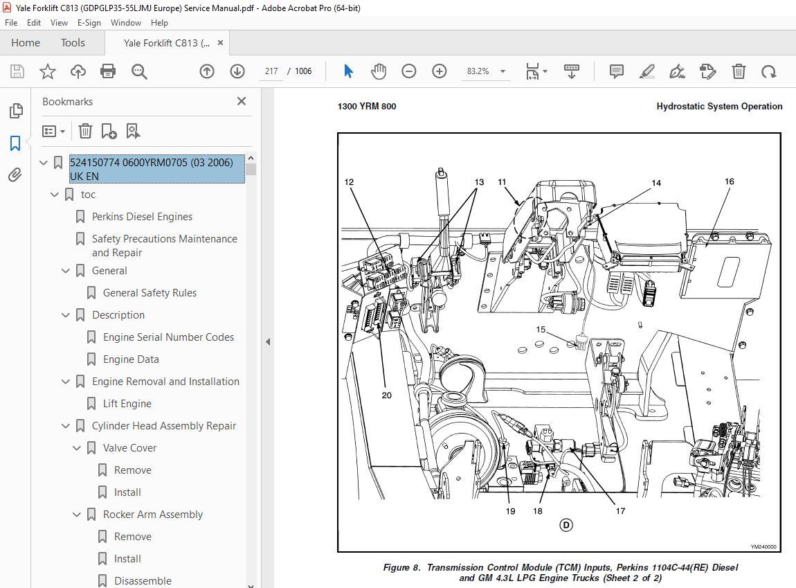
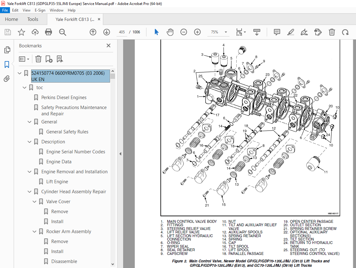
TABLE OF CONTENTS:
Yale Forklift C813 (GDPGLP35-55LJMJ Europe) Service Manual – PDF DOWNLOAD
524150774 0600YRM0705 (03 2006) UK EN 1
toc 1
Perkins Diesel Engines 1
Safety Precautions Maintenance and Repair 2
General 9
General Safety Rules 9
Description 10
Engine Serial Number Codes 13
Engine Data 13
Engine Removal and Installation 15
Lift Engine 15
Cylinder Head Assembly Repair 15
Valve Cover 15
Remove 15
Install 16
Rocker Arm Assembly 16
Remove 16
Install 16
Disassemble 16
Inspect 17
Assemble 17
Valve Clearance Adjustments 17
Four-Cylinder Engines 18
Six-Cylinder Engines 18
Valve Springs 18
Cylinder Head Assembly 20
Remove 20
Install 22
Valves and Valve Springs 26
Remove 26
Inspect 26
Install 27
Valve Guides 27
Inspect 27
Remove 28
Install 28
Cylinder Head and Valve Seats 28
Inspect 28
Repair 28
New Valve Seats, Install 28
Piston and Connecting Rod Assemblies Repair 30
Rod Bearings 30
Remove 31
Install 31
Piston and Connecting Rod Assembly 32
Service Note 32
Remove 32
Install 33
Piston Rings 34
Remove 34
Inspect 34
Install 34
Piston and Connecting Rod 35
Disassemble 35
Inspect 36
How to Select Correct Replacements 36
Install 37
Piston Cooling Jets 37
Remove 37
Install 38
Crankshaft Assembly Repair 38
General 38
Crankshaft Pulley 39
Engine AR, Remove 39
Engines YG and YH, Remove 39
Inspect 40
Engine AR, Install 40
Engines YG and YH, Install 40
Rear Oil Seal 41
Replace 41
Main Bearings 42
Remove 42
Inspect 43
Install 43
Thrust Washers 43
Crankshaft Axial Movement, Check 43
Remove 44
Install 44
Crankshaft 45
Remove 45
Inspect 45
Install 45
Flywheel 47
Remove 47
Ring Gear, Replace 47
Install 47
Flywheel Housing 48
Remove 48
Install 48
Timing Case and Timing Gears Repair 49
General 49
Timing Case Cover 49
Remove 49
Install 50
Front Oil Seal 50
Remove 50
Install 50
Crankshaft Pulley Wear Sleeve 51
Install 51
Idler Gear and Hub 51
Remove 51
Install 52
Air Compressor Drive, Bendix 53
Disassemble 53
Assemble 54
Fuel Injection Pump Gear 54
Remove 55
Install 55
Camshaft Gear 56
Remove 56
Install 56
Crankshaft Gear 57
Remove 57
Install 57
Timing Case 57
Remove 57
Install 58
Camshaft and Tappets 59
Remove 59
Install 59
Cylinder Block Assembly Repair 60
Description 60
Cylinder Block 60
Disassemble 60
Inspect 61
Assemble 61
Cylinder Bore (Four-Cylinder Engines) 61
Cylinder Liner (Six-Cylinder Engines) 62
Inspect 62
Cylinder Liner Condition, Check 62
Remove 63
Service Liner, Install 63
Partially Finished Liner, Install 65
Engine Timing 65
Description 65
How to Set Number One Piston to TDC on Compression Stroke 67
How to Set Number One Piston to TDC on Compression Stroke (Alter 67
Valve Timing, Check 68
Fuel Injection Pump Timing, Check 69
Turbocharger – Engine YH Repair 70
General 70
Remove 70
Install 70
Impeller and Compressor Housing, Clean 71
Lubrication System Repair 72
General 72
Oil Filter, Replace 72
Filter Head 72
Remove and Install 72
Oil Sump 73
Remove 73
Install 73
Oil Pump 73
Remove 73
Inspect 74
Install 75
Relief Valve 75
Remove 75
Disassemble 76
Inspect 76
Assemble 76
Install 76
Idler Gear Shaft, Replace 77
Remove 77
Remove (Alternative) 77
Install 78
Install (Alternative) 78
Install (Alternative for Four-Cylinder Engines Only) 79
Fuel System Repair 79
Description 79
Fuel Injection Pump 80
Remove 80
Install 81
Check and Adjust 81
Fuel System Air Removal 82
Fuel Filter, Replace 83
Canister Type 83
Quick Release Canister Type 84
Fuel Injectors 85
Remove 85
Inspect 85
Install 85
Fuel Pump 86
Remove 86
Disassemble 86
Assemble 87
Install 88
Test 88
Cooling System Repair 88
General 88
Thermostat 88
Remove 88
Install 89
Test 89
Coolant Pump 89
Remove 89
Disassemble 90
Assemble 91
Install 94
Fan and Fan Drive 94
Remove 94
Install 95
Oil Cooler (Six-Cylinder Engines) 95
Remove 95
Disassemble and Assemble 95
Install 96
Oil Cooler Bypass Valve 96
Electrical Equipment Repair 96
Drive Belts 96
Adjustment 96
Remove 97
Install 97
Alternator 97
Remove 97
Install 97
Starter Motor 98
Remove 98
Install 98
Cold Start Aid 98
Air Compressor – Engines YG and YH 98
General 98
Repair 98
Remove 98
Install 99
Rotary Exhauster Replacement 100
Remove 100
Clean 100
Install 100
Engine Specifications 101
Cylinder Head Assembly 101
Piston and Connecting Rods 104
Crankshaft Assembly 107
Crankshaft Overhaul 108
Timing Case and Drive Assembly 110
Engine Block Assembly 111
Turbocharger 114
Lubrication System 114
Fuel System 115
Cooling System 117
Flywheel and Housing 117
Electrical Equipment 118
Torque Specifications 118
Cylinder Head Assembly 118
Piston and Connecting Rod Assemblies 118
Crankshaft Assembly 118
Timing Case and Drive Assembly 119
Turbocharger 119
Lubrication System 119
Fuel System 119
Cooling System 119
Flywheel 119
Auxiliary Equipment 119
Special Torque Specifications 120
Flywheel and Housing 120
Turbocharger 120
Electrical Equipment 120
Auxiliary Equipment 120
Special Tools* 121
Troubleshooting 126
tables 1
Table 1 Cylinder Head 101
Table 2 Valve Guides 101
Table 3 Inlet Valves 101
Table 4 Exhaust Valves 102
Table 5 Valve Springs 104
Table 6 Tappets 104
Table 7 Rocker Arm Shaft 104
Table 8 Rocker Arms and Bushings 104
Table 9 Pistons (Engine AR) 104
Table 10 Pistons (Engines YG and YH) 104
Table 11 Piston Rings (Engine AR) 105
Table 12 Piston Rings (Engines YG and YH) 105
Table 13 Piston Pins 106
Table 14 Connecting Rods 106
Table 15 Small End Bushings 106
Table 16 Connecting Rod Bearings (Engines AR and YG) 106
Table 17 Connecting Rod Bearings (Engine YH) 106
Table 18 Piston Cooling Jets 107
Table 19 Crankshaft 107
Table 20 Main Bearings 107
Table 21 Crankshaft Thrust Washers 107
Table 22 Crankshaft Heat Treatment 108
Table 23 Crankshaft Overhaul Specifications 108
Table 24 Maximum Variation (Run-out) 110
Table 25 Camshaft 110
Table 26 Camshaft Thrust Washer 110
Table 27 Camshaft Gear 110
Table 28 Gear for Fuel Injection Pump 111
Table 29 Crankshaft Gear 111
Table 30 Idler Gear and Hub 111
Table 31 Cylinder Block (Engine AR) 111
Table 32 Cylinder Bore Specifications 112
Table 33 Cylinder Block (Engines YG and YH) 113
Table 34 Cylinder Liners (Engines YG and YH) 113
Table 35 Cylinder Liner Specifications (Partially Finished) 113
Table 36 Oil Pump (Engine AR) 114
Table 37 Oil Pump (Engines YG and YH) 114
Table 38 Idler Gear for Oil Pump 114
Table 39 Relief Valve 115
Table 40 Oil Filter 115
Table 41 Lucas Fuel Injection Pump 115
Table 42 Fuel Injector Codes 116
Table 43 Fuel Pump (Engine AR) 117
Table 44 Fuel Pump (Engines YG and YH) 117
Table 45 Fuel Filter 117
Table 46 Coolant Pump 117
Table 47 Thermostat 117
Table 48 Fan Drive Housing 117
Table 49 Limits for Flywheel Run Out and Alignment (Total Indic 117
Table 50 Alternator 118
Table 51 Starter Motor 118
Table 52 Cold Start Aid 118
Table 53 List of Possible Causes 126
524150791 2200YRM0002 (01 2016) UK EN 131
General 135
Description 136
Alternator Repair 138
Alternator Type A 138
Remove and Disassemble 138
Clean 140
Assemble 140
Install 141
Alternator Type B 144
Remove and Disassemble 144
Clean 144
Assemble 145
Install 146
General Check and Adjustment 146
Low Output Check (Type A or Type B) 147
High Output Check (Type A or Type B) 150
Brushes Circuit Check 151
Delco Alternators 151
Motorola Alternators 151
Diodes Check 152
Diode Bridge Check 152
Delco and Leece-Neville Alternators 152
Motorola Alternators 152
Rotor Field Winding Check 153
Stator Windings Check 154
Voltage Regulator Check 154
Troubleshooting 154
524150797 8000YRM0231 (02 2023) US EN 159
General 165
Threaded Fasteners 165
Nomenclature, Threads 165
Strength Identification 166
Cotter (Split) Pins 167
Fastener Torque Tables 172
Conversion Table 174
524150797 8000YRM0231 (03 2020) UK EN 181
General 185
Threaded Fasteners 185
Nomenclature, Threads 185
Strength Identification 186
Cotter (Split) Pins 187
Fastener Torque Tables 192
Conversion Table 194
524153601 1300YRM0800 (03 2004) UK EN 201
toc 201
Hydrostatic Transmission 201
Safety Precautions Maintenance and Repair 202
General 205
Component Descriptions 205
Power Unit General Arrangement 205
Hydrostatic Pump Mounting 206
Perkins 1004-42 and 1104C-44(RE) Diesel Engines 206
GM 4 3L LPG Engine 206
Hydrostatic Control Components 206
Hydrostatic System Operation 209
Hydrostatic Pump 209
Drive Axle 210
Transmission Control Module (TCM) 211
Perkins 1004-42 Diesel Engine Trucks 211
Perkins 1104C-44(RE) Diesel and GM 4 3L LPG Engine Trucks 212
Transmission Control Inputs 212
Key Switch 212
Forward/Reverse Switches, Perkins 1004-42 Diesel Engine Trucks 212
Forward/Reverse Switches, Perkins 1104C-44(RE) Diesel and GM 4 3 212
Parking Brake Switches 215
Engine Speed Sensor 215
Wheel Speed Sensors, Perkins 1104C-44(RE) Diesel and GM 4 3L LPG 215
Brake Pressure Sensor 215
Charge Pressure Sensor 215
Transmission Oil Temperature Sensor 215
Throttle Pedal Switch, Perkins 1004-42 Diesel Engine Trucks 215
Throttle Pedal Switch, Perkins 1104C-44(RE) Diesel and GM 4 3L L 218
Throttle Pedal Position Sensor, Perkins 1004-42 Diesel Engine Tr 218
Throttle Pedal Position Sensor, Perkins 1104C-44(RE) Diesel and 218
Transmission Control Outputs 218
Forward/Reverse Solenoid Enable, Perkins 1004-42 Diesel Engine T 218
Forward/Reverse Solenoid Enable, Perkins 1104C-44(RE) Diesel and 218
Forward/Reverse Solenoids, Perkins 1104C-44(RE) Diesel and GM 4 220
Engine Start Enable 220
Fuel Cutoff Relay 220
Retard Valve 220
Pilot Solenoid Valve, Perkins 1004-42 Diesel Engine Trucks 220
Pilot Solenoid Valve Enable, Perkins 1104C-44(RE) Diesel and GM 220
Transmission Fault Warning Light 220
Transmission Overspeed Warning Light 222
Oil Temperature Warning Light 222
Throttle-Up Inputs 222
Lift Lever Switch, Perkins 1004-42 Diesel Engine Trucks 222
Lift Lever Position Sensor, Perkins 1004-42 Diesel Engine Trucks 223
Lift Lever Switch, Perkins 1104C-44(RE) and GM 4 3L LPG Engine T 223
Lift Lever Position Sensor, Perkins 1104C-44(RE) and GM 4 3L LPG 223
Tilt/Auxiliary Lever Switches, Perkins 1004-42 Diesel Engine Tru 223
Tilt/Auxiliary Lever Switches, Perkins 1104C-44(RE) Diesel and G 223
Engine Throttle Position Sensor, Perkins 1004-42 Diesel Engine T 223
Throttle-Up Outputs, Perkins 1004-42 Diesel Engine Trucks 223
Throttle-Up Motor 223
Throttle Servo Motor – Perkins 1104C-44(RE) Diesel and GM 4 3L L 224
Transmission Control Module (TCM) Operation 225
How the TCM Begins Operation 225
TCM Operation on a Running Lift Truck 225
Lift Trucks With Perkins 1004-42 Diesel Engine 225
Lift Trucks With Perkins 1104C-44(RE) Diesel and GM 4 3L LPG Eng 225
Event and Fault Detection 225
Diagnostic Connector 226
Hydrostatic Transmission Features 226
Travel Control 226
Lift Trucks With The Perkins 1004-42 Diesel Engine 226
Lift Trucks With the Perkins 1104C-44(RE) Diesel and GM 4 3L LPG 226
Antistall 227
Dynamic Braking 227
Brake Inching 227
Overspeed Control 227
Hydraulic Retard 228
Wheel Anti-spin 228
Temperature Compensation 228
Low Charge Pressure Compensation 229
Quick-Roll 230
Throttle-Up (Option) 230
Perkins 1004-42 Diesel Engine Lift Trucks Only 230
Hydraulic Circuit 230
Loop Circuit 230
Charge Circuit 233
Pilot Supply Circuit 233
Pilot Control Circuit 233
Retard Circuit 233
Cooling Oil Supply Circuit 234
Cooling Circuit 234
tables 201
Table 1 Electronic Transmission Control System – Perkins 1004-4 208
Table 2 Electronic Transmission Control System – Perkins 1104C- 208
524153606 1300YRM0801 (03 2004) UK EN 237
toc 237
Hydrostatic Transmission 237
Safety Precautions Maintenance and Repair 238
General 243
TransLink™ User Interface Software 243
Connecting PC to TCM 243
Transmission Fluid 244
Startup and Calibration 246
Startup Procedure Following Service or Repairs 246
Throttle System Calibration 247
Perkins 1004-42 Diesel Engine 247
Perkins 1104C-44(RE) Diesel Engine and GM 4 3L LPG Engine 248
Throttle System Calibration Checks 248
Perkins 1104C-44(RE) Diesel Engine and GM 4 3L LPG Engine Lift T 248
Hydrostatic Pump Repair 248
Remove 248
Install 252
Charge Pump Repair 252
Remove 252
Inspect 253
Install 253
Pump Control Valve Repair 255
Remove 255
Inspect 255
Install 255
Replace Pilot Solenoid 255
Replace Directional Solenoid Pair 255
Clean or Replace Pilot Supply Filter Disk 255
Replace Loop Relief Cartridges 256
Replace Filter Cartridge 256
Replace Filter Head 257
Drive Axle Repair 257
Remove and Disassemble 257
Inspect 260
Assemble and Install 260
Wheel Speed Sensors, Replace 261
Lift Trucks With Perkins 1104C-44(RE) Diesel Engine and GM 4 3L 261
Axle Valve Repair 261
Remove 261
Inspect 261
Install 261
Replace Pressure Reducing Valve 261
Replace Shuttle Valve 262
Replace Charge Supply Regulator 262
Replace Retard Valve 262
Replace Temperature Sensor 262
Transmission Control Module (TCM) Replacement 263
Throttle Pedal/ Foot Directional Control Pedal Repair 263
Remove Standard Throttle Pedal 263
Install Standard Throttle Pedal 263
Lift Trucks With Perkins 1004-42 Diesel Engine 263
Lift Trucks With Perkins 1104C-44(RE) Diesel Engine and GM 4 3L 263
Remove and Disassemble Foot Directional Control Pedal 264
Assemble and Install Foot Directional Control Pedal 264
Replace Throttle Pedal Position Sensor 267
Replace Throttle Pedal Switch 267
Throttle-Up Assembly Replace – Perkins 1004-42 Diesel Engine 268
Remove 268
Inspect 268
Install 268
Replace Throttle Motor 269
Replace Engine Throttle Position Sensor 269
Throttle Servo Motor Replace – Perkins 1104C-44(RE) Diesel and G 269
Remove 269
Perkins 1104C-44(RE) Diesel Engine 269
GM 4 3L LPG Engine 269
Inspect 271
Install 271
Perkins 1104C-44(RE) Diesel Engine 271
GM 4 3L LPG Engine 271
Throttle-Up Switch Assembly Repair 273
Remove 273
Install 273
Replace Lift Lever Position Sensor 273
Replace Throttle-Up Switches 273
Hydrostatic Drive Checks and Adjustments 274
Swashplate Positioning Cylinder 274
Truck Travel Speed Limit Adjustment 275
Perkins 1004-42 Diesel Engine 275
Perkins 1104C-44(RE) Diesel Engine and GM 4 3L LPG Engine 275
Charge Pressure 275
Pilot Supply Pressure 276
Pilot Pressure 276
POR Pressure 276
Loop Pressure 276
Throttle Pedal/ Foot Directional Control Pedal Checks and Adjust 277
Throttle Cable 277
Perkins 1004-42 Diesel Engine Trucks 277
Pedal Stop 277
Standard Throttle Pedal 277
Perkins 1004-42 Diesel Engine Trucks 277
Perkins 1104C-44(RE) Diesel and GM 4 3L LPG Engine Trucks 277
Foot Directional Control Pedal 277
Perkins 1004-42 Diesel Engine Trucks 277
Perkins 1104C-44(RE) Diesel and GM 4 3L LPG Engine Trucks 277
Foot Directional Control Pedal Operation 278
Throttle Pedal Position Sensor 278
Throttle Pedal Switch 278
Foot Directional Control Pedal Switch 279
Throttle-Up Assembly Checks and Adjustments 280
Engine Throttle Position Sensor 280
Throttle-Up Motor 281
Throttle Servo Motor Checks and Adjustments 281
Throttle Servo Motor Position Sensor 281
Throttle Servo Motor 282
Throttle-Up Switch Assembly Checks and Adjustments 283
Throttle-Up Switches 283
Lift Lever Position Sensor 283
Sensor Checks 284
Charge Pressure Sensor 284
Brake Pressure Sensor 284
Oil Temperature Sensor 285
Engine Speed Sensor 285
Left Speed Sensor 286
Right Speed Sensor 287
Event Codes 287
Perkins 1004-42 Diesel Engine Trucks 287
Event Code Descriptions – Perkins 1004-42 Diesel Engine Trucks 288
Perkins 1104C-44(RE) Diesel Engine and GM 4 3L LPG Trucks 294
Event Code Descriptions – Perkins 1104C-44(RE) Diesel and GM 4 3 295
Troubleshooting 303
Perkins 1004-42 diesel engine trucks only 307
Perkins 1004-42 diesel engine trucks only 308
Perkins 1104C-44(RE) diesel and GM 4 3L LPG engine trucks 309
Perkins 1104C-44(RE) diesel and GM 4 3L LPG engine trucks 309
tables 237
Table 1 Charge and Brake Sensor Outputs 285
Table 2 Oil Temperature Sensor Outputs 285
Table 3 Engine Speed Sensor Outputs 286
Table 4 Wheel Speed Sensor Outputs – Perkins 1104C-44(RE) Diese 286
524153897 0600YRM0590 (04 2014) UK EN 313
524153904 1600YRM0732 (10 2003) UK EN 365
toc 365
Steering Control Unit 365
Safety Precautions Maintenance and Repair 366
General 369
Description 369
Operation 369
Steering Wheel and Column Assembly Repair 371
Remove and Disassemble 371
Assemble and Install 371
Steering Control Unit 374
Disassemble 374
Clean 376
Assemble 377
System Air Removal 380
Troubleshooting 380
524153909 1900YRM0743 (06 2005) UK EN 385
toc 385
Hydraulic System 385
Safety Precautions Maintenance and Repair 386
General 389
Description 389
Operation 391
Hydraulic Pump GLP/GDP 3 5-5 5LJ/MJ (GP/GLP/GDP70-120LJ/MJ) 391
Hydraulic Pump GC070-120LJ/MJ 391
Main Control Valve 391
Steering Control Unit 392
Specifications 392
Hydraulic System Capacity (Powershift) 392
Hydraulic System Capacity (Hydrostatic) 392
Hydraulic Tank Capacity (Powershift and Hydrostatic) 393
Hydraulic Tank Capacity 393
Relief Pressures @ 2200 RPM, 50 to 80 C ( 120 to 180 F) 393
Hydraulic Pump Flow to Valve 393
Steering Priority Flow 393
Troubleshooting 393
Lift, Lower and Tilt Circuit 394
Steering Circuit 395
524153910 2000YRM0754 (12 2003) UK EN 399
toc 399
Main Control Valve 399
Safety Precautions Maintenance and Repair 400
General 403
Description 403
Operation 403
Lift Section 403
Tilt and Auxiliary Sections 407
Reattaching the Clevis End of the Tilt Spool 408
Relief Valve 408
Main Control Valve Repair 408
Remove and Disassemble 408
Clean and Inspect 410
Assemble 412
Install 412
Pressure Relief Valve Check and Adjustment 413
Main Relief Valve (Lift) 413
Steering Relief Valve 413
Secondary Relief Valve (Tilt and Auxiliary) 416
Specifications 417
Troubleshooting 417
524153913 2200YRM0755 (10 2003) UK EN 423
toc 423
Starter 423
Safety Precautions Maintenance and Repair 424
General 427
Description 427
Yoke Assembly 428
Armature Assembly 428
Clutch Assembly 428
Magnetic Switch Assembly 428
Operation 428
Starter Repair 429
Remove 429
Disassemble 430
Clean 433
Assemble 434
Install 437
General Checks and Adjustments 437
Armature Tests 438
Armature Short Circuit Test 438
Armature Winding Ground Test 438
Commutator Run-Out Test 438
Yoke Test 439
Brush and Brush Holder Check 439
Brush Holder Insulation Test 439
Clutch Test 439
Magnetic Switch Test 440
Pull-In Test 440
Hold-In Test 440
Return Test 440
Performance Tests 441
No-Load Test 441
Troubleshooting 441
524153914 2200YRM0107 (03 2008) UK EN 447
toc 447
High Energy Ignition (HEI) System 447
Safety Precautions Maintenance and Repair 448
Description 451
Distributor Repair 453
Remove 453
Disassemble 453
Assemble 459
Install, If Crankshaft WAS NOT Rotated when Distributor was Remo 460
Install, If Crankshaft WAS Rotated when Distributor was Removed 460
Ignition Coil Replacement 462
Some Four- and Six-Cylinder Models 462
Remove 462
Install 462
V8, Some Four- and Six-Cylinder Models 463
Remove 463
Install 463
Electronic Module Replacement 464
Remove 464
Install 464
Sensing Coil Replacement 466
Remove 466
Install 466
Spark Plugs Replacement 466
Remove 466
Install 467
Visual Check 467
High Voltage Wires Check 467
Ignition Coil Check 468
Coil in Distributor Cap Design 468
Separate Coil Design 468
Sensing Coil, Check 469
Electronic Module Check 469
Ignition Timing Adjustment 470
GM V8-366 (6-liter) Ignition System Check 471
GM V6-LPG (4 3 liter) GM V6-LPG (4 3 liter) Ignition Timing and 471
Specifications 471
Troubleshooting 472
524153915 2200YRM0756 (02 2007) UK EN 477
toc 477
Instrument Panel Indicators and Senders 477
Safety Precautions Maintenance and Repair 478
General 481
Description 481
Instruments and Senders 481
Password Function 487
Supervisor Password Function 487
Entering Operator Passwords 487
Deleting Operator Passwords 488
Retrieve the Most Recent Operator Password Used to Enable the Tr 488
Display All Operator Passwords Programmed Into the System 488
Enable and Disable Operator Passwords Function 488
Allow Supervisor Password to Enable the Truck to Start 488
Operator Passwords Function 488
Component Replacement – General Information 489
Sender Replacement 489
Fuel Level Sender 489
Pressure and Temperature Sender 490
Seat Sensor, Operator Presence System (OPS) 491
Remove 491
Install 491
Operator Presence System Module Replacement 491
Remove 491
Install 493
Display Panel Replacement 494
Specifications 496
Troubleshooting 497
Troubleshooting For Operator Presence System GP/GLP/GDP70-120LJ/ 498
Troubleshooting For Operator Presence System GC70-120LJ/MJ (C818 500
tables 477
Table 1 Instrument Panel Description 482
Table 2 Sender Description 486
Table 3 Meter and Sender Specifications 496
Table 4 Troubleshooting Procedure for the Operator Presence Mod 498
Table 5 Troubleshooting Procedure for the Operator Presence Mod 500
524153919 4000YRM0741 (03 2005) UK EN 505
toc 505
Lift Cylinders 505
Safety Precautions Maintenance and Repair 506
Safety Procedures When Working Near Mast 509
General 511
Description 511
Lowering Control Valve (Velocity Fuse) 511
Lift Cylinder Repair 514
Remove 514
Disassemble 515
Assemble 515
Install 515
Lift System Leak Check 516
Troubleshooting 517
524153920 4000YRM0736 (07 2010) UK EN 521
toc 521
Masts 521
Safety Precautions Maintenance and Repair 522
General 525
Description and Operation 525
Carriages 525
Two-Stage Mast With Limited Free-Lift 525
Two-Stage Mast With Full Free-Lift 526
Three-Stage Mast With Full Free-Lift 527
Safety Procedures When Working Near Mast 529
Fork Replacement 531
Remove 532
Install 532
Carriage Repair 533
Remove 533
Sideshift Carriage Repair 535
Remove 535
Disassemble 535
Assemble 535
Install 535
Two-Stage Mast With Limited Free-Lift Repair 537
Remove, GLP/GDP3 5-5 5LJ/MJ (GP/GLP/GDP070-120LJ/MJ) Model Lift 537
Remove, GC070-120LJ/MJ, ERC070-120HG (A839), and ERC35-55HG (ERC 539
Disassemble 542
Clean and Inspect 542
Assemble 543
Install, GLP/GDP3 5-5 5LJ/MJ (GP/GLP/GDP070-120LJ/MJ) Lift Truck 544
Install, GC070-120LJ/MJ, ERC070-120HG (A839), and ERC35-55HG (ER 546
Two-Stage Mast With Full Free-Lift Repair 548
Remove 548
Disassemble 548
Clean and Inspect 550
Assemble 550
Install 550
Three-Stage Mast With Full Free-Lift Repair 552
Remove 552
Disassemble 552
Clean and Inspect 556
Assemble 556
Install 557
Mast Operation Check 563
Lift and Tilt System Leak Check 564
Lift System 564
Tilt System 565
Tilt Cylinder Stroke and Backward Tilt Angle Adjustment 566
Lift Chain Adjustments 568
Mast Adjustments 570
Carriage Adjustment 572
Troubleshooting 573
tables 521
Table 1 Tilt Cylinder Leak Check Specifications, GC070-120LJ/MJ 565
Table 2 Hook-Type Carriage Chain Adjustment 568
Table 3 Pin-Type Carriage Chain Adjustment 569
524173800 0100YRM0726 (02 2007) UK EN 579
toc 579
Frame 579
Safety Precautions Maintenance and Repair 580
General 583
Description 583
Counterweight Repair 583
Remove 583
Install 584
Hood Repair 584
Remove 584
Install 584
Overhead Guard Repair 586
Remove 586
Inspect 586
Install 586
LED Backup and Brake Lights, Replace 586
Remove 586
Install 586
Operator Restraint System Repair 587
Automatic Locking Retractor (ALR) 587
Emergency Locking Retractor (ELR) 588
Radiator Repair 589
Remove 589
Install 589
Exhaust System Repair 591
Muffler 591
Remove 591
Install 591
LPG/Gas Engine Exhaust Pipe – Lift Trucks Without Low Emissions 594
Remove 594
Install 594
EPA Compliant LPG/Gas Engine Exhaust System 594
Remove 594
Install 596
Diesel Engine Exhaust Pipe 596
Remove 596
Install 598
Engine Repair 598
Remove 598
Install 600
Throttle Pedal Adjustment 602
Perkins 1104C-44(RE) Diesel Engine 602
Lift Trucks With an Accelerator Pedal 602
Lift Trucks With a Foot Directional Control Pedal 603
Fuel and Hydraulic Tanks Repair 605
Inspect 605
Small Leaks, Repair 605
Large Leaks, Repair 605
Clean 605
Steam Method 605
Chemical Solution Method 605
Other Preparation Methods for Repair 606
Safety Labels 606
tables 579
Table 1 Weight of Counterweights 583
524173801 0100YRM0778 (06 2004) UK EN 611
toc 611
Operators Cab 611
Safety Precautions Maintenance and Repair 612
General 615
Cab Repair 616
Remove 616
Install 617
Switch Panel 617
Window Wipers Replacement 618
Front Wiper Assembly 618
Rear Wiper Assembly 618
Door Handle Assembly 620
Fuse Panel 621
Heater Assembly 621
Remove 621
Install 621
Window Replacement 623
Options 625
Rear Strobe Lights 625
Heavy-Duty Air Cleaner 625
Label Replacement 626
Electrical Schematics 626
tables 611
Table 1 Material Specifications for Cab Windows 623
524173802 0700YRM0740 (02 2004) UK EN 631
toc 631
Cooling System 631
Safety Precautions Maintenance and Repair 632
General 635
Description 635
Radiator 635
Radiator Cap 635
Thermostat 635
Water Pump 636
Fan and Fan Shroud 636
Drive Shaft 636
Cooling System Checks 636
Exhaust Leaks into Cooling System 636
Radiator Repair 636
Checks 636
Clean 636
Cooling System 638
Drain 638
Fill 638
Water Pump Repair 638
Checks 638
Thermostat Repair 639
Checks 639
Fan Assembly Repair 639
Remove 639
Inspect 639
Install 639
Fan Belt Repair 642
Remove 642
Install 642
Drive Shaft Repair 642
Remove 642
Install 642
Troubleshooting 642
524173803 0900YRM0745 (09 2003) UK EN 647
toc 647
LPG Fuel System 647
Safety Precautions Maintenance and Repair 648
General 651
Description and Operation 651
Fuel Tank 651
Fuel Filter and Fuel Valve Unit 651
LPG Convertor Vaporizer (IMPCO) 651
LPG Controller (Dana EPIC/Teleflex-GFI) 655
Filter Section 655
Lock-Off Section 655
Converter Section – Primary Regulation (Stage 1) 655
Converter Section – Secondary Regulation (Stage 2) 655
Carburetor 656
Governor 659
Two-Way Valves, Open-Loop System 659
Closed-Loop Fuel Control 659
O E Tune Valve, Closed-Loop Fuel System 660
Oxygen Sensor, Closed-Loop Fuel System 660
LPG Tank Repair 660
Remove 660
Install 660
Hydrostatic Relief Valve Repair 661
Remove and Install 661
Filter Unit Repair 662
Fuel Filter Element, Replace 662
Diaphragm and Fuel Valve, Replace 662
Hoses Replacement 662
LPG Convertor Vaporizer (IMPCO) Repair 664
Remove 664
Disassemble 664
Clean 664
Inspect 664
Assemble 666
Install 670
LPG Controller (Dana EPIC/Teleflex-GFI) Repairs 670
Remove 670
Disassemble 670
Converter Section 670
Filter Section 672
Lock-Off Section 672
Clean 674
Inspect 674
LPG Controller Assembly 674
Filter Section 674
Lock-Off Section 674
Converter Section 674
Carburetor Repair 676
Remove 676
Disassemble 676
Clean 676
Assemble 677
Install 677
Governor Assembly Repair 678
Governor Motor Repair 680
Remove 680
Install 680
Filter Unit Check 680
Vaporizer Check 681
Pressure Reducer Valve 681
Vapor Valve 681
Carburetor Adjustment 681
Idle Mixture 681
Idle Speed 681
Throttle Linkage Adjustment 681
LPG Controller Adjustments (Dana EPIC/Teleflex-GFI) 682
Filter and Lock-Off Sections Leak Check 682
Lock-Off Section Functional Check 683
Controller Pressure Test 683
Adjustment of Secondary Lever 684
Final Adjustment Check 684
Troubleshooting 685
524173804 1300YRM0727 (06 2004) UK EN 695
toc 695
Two-Speed Powershift Transmission 695
Safety Precautions Maintenance and Repair 696
General 699
Mechanical Description 699
Torque Converter 700
Transmission Pump 700
Shaft Assemblies 700
Input (Reverse) Shaft 700
Counter (Forward) Clutch Shafts 700
Clutch Assemblies 700
Output Gear and Pinion 701
Electronic Control Unit 701
Hydraulic Operation 702
Torque Converter 702
Seal Rings 703
Control Valve 703
Clutch Pressure Regulator 703
Inching Spool Assembly 703
Direction Spool 705
Modulator Circuit 705
Torque Converter Regulator 705
Foot Directional Control Pedal 706
Foot Directional Control Pedal Start Circuit 706
Direction Control Lever 707
Oil Flow Diagrams 707
Neutral 708
Modulator Operation 709
Forward-Low 711
Forward-Low-Inching 711
Reverse 717
524173805 1300YRM0728 (08 2006) UK EN 725
toc 725
Two-Speed Powershift Transmission 725
Safety Precautions Maintenance and Repair 726
General 729
Transmission Repair 729
Remove 729
Install 729
Clutch Packs Repair 732
Remove and Disassemble 732
Clutch Assemblies, Disassemble 735
Inspect 737
Assemble and Install 738
Clutch Assemblies, Assemble and Install 738
Differential Repair 746
Remove and Disassemble 746
Inspect 747
Original Parts, Assemble and Install 747
New Parts, Assemble and Install 747
Adjustments With Original Shim Pack 748
Adjustments Without Original Shim Pack 749
Differential and Ring Gear Assembly, Assemble 751
Control Valve Repair 756
Remove and Disassemble 756
Inspect 758
Assemble and Install 758
Foot Directional Control Pedal Repair 759
Remove and Disassemble 759
Assemble and Install 759
Direction Control Lever 762
Remove and Disassemble 762
Assemble and Install 762
Stall Test 763
Inching/Brake Pedal Adjustment 764
Foot Directional Control Pedal Neutral Start Switch Adjustment 766
Foot Directional Control Pedal Neutral Start Switch Test 767
Test 1 767
Test 2 767
Electronic Control Unit Check 768
Oil Pressure Check 769
Transmission Pump Relief Valve, Test Port 1, Check 770
Input (Reverse) Clutch Pressure, Test Port 2, Check 770
Counter (Forward) Clutch Pressure, Test Ports 3 and 4, Check 770
Torque Converter Regulator, Test Port 5, Check 770
Lubrication Circuit Oil Pressure, Test Port 6, Check 770
Modulator Pressure, Test Port 7, Check 770
2-Speed Transmission Will Not Shift 771
Troubleshooting 772
Troubleshooting – Pressure Tests 775
tables 725
Table 1 Pinion Variation Numbers Examples 748
Table 2 Ring and Pinion Tooth Contact Adjustment 754
Table 3 Stall Speeds (New Engines) 763
Table 4 Electronic Control Unit Connector 768
Table 5 Transmission Pressure Port Check 769
524173806 1400YRM0731 (09 2003) UK EN 779
toc 779
Drive Axle 779
Safety Precautions Maintenance and Repair 780
General 783
Description 783
Drive Axle Repair 783
Remove and Disassemble 783
Clean and Inspect 785
Assemble and Install 785
Troubleshooting 787
524173807 1600YRM0733 (09 2003) UK EN 791
toc 791
Steering Axle 791
Safety Precautions Maintenance and Repair 792
General 795
Description 795
Steering Axle Assembly Repair 796
Remove 796
Install 796
Wheels and Hub Repair 797
Remove and Disassemble 797
Clean 797
Inspect 797
Assemble and Install 797
Spindles and Bearings Repair 798
Remove 798
Clean 798
Inspect 798
Assemble and Install 798
Tie Rods Repair 799
Remove 799
Clean 799
Inspect 799
Install 799
Steering Cylinder Repair 799
Remove and Disassemble 799
Clean and Inspect 799
Assemble and Install 800
Troubleshooting 801
524173808 1800YRM0734 (05 2005) UK EN 805
toc 805
Brake System 805
Safety Precautions Maintenance and Repair 806
General 809
Description and Operation 809
Brake Booster and Master Cylinder 809
Service Brake Assembly 809
Parking Brake 809
Brake Shoe Assemblies Repair 810
Remove and Disassemble 810
Clean 812
Inspect 812
Assemble and Install 813
Brake Booster and Master Cylinder Repair 816
Remove 816
Disassemble 816
Clean and Inspect 816
Assemble 816
Install 816
Brake Booster Filter, Replace 816
Parking Brake Repair 819
Remove and Disassemble 819
Assemble and Install 819
Brake System Air Removal 819
Brake Pedal Adjustment 819
Parking Brake Adjustment 820
Parking Brake Not Applied Switch Test 820
Parking Brake Switch Test ( Foot Directional Control Pedal Only) 821
Brake Shoes Adjustment 821
Troubleshooting 822
524173809 1900YRM0753 (09 2003) UK EN 827
toc 827
Hydraulic Gear Pump 827
Safety Precautions Maintenance and Repair 828
General 831
Description 831
Operation 831
Hydraulic Gear Pump Repair 832
Remove 832
Disassemble 832
Clean 834
Inspect 834
Assemble 835
Install 835
Pump Output Check 836
Method No 1 836
Method No 2 837
Hydraulic System Air Check 838
Troubleshooting 838
524173810 2100YRM0735 (11 2004) UK EN 843
toc 843
Tilt Cylinders 843
Safety Precautions Maintenance and Repair 844
General 847
Description 847
Tilt Cylinder Repair 847
Remove 847
Disassemble 848
Clean 849
Inspect 849
Assemble 849
Install 849
Tilt Cylinder Leak Check 850
Tilt Cylinder Stroke and Mast Tilt Angle Adjustment 850
Troubleshooting 850
524173811 2200YRM0744 (09 2003) UK EN 855
toc 855
Carbureted Engine Management System (CEMS) 855
Safety Precautions Maintenance and Repair 856
Description 859
Ignition Control System 860
Setting Timing Reference 860
Idle Speed Control System 860
Curb Idle Setting Procedure 860
Governor Control System 861
Closed-Loop Fuel System 862
Closed-Loop Fuel Control 862
Entering Closed-Loop Control 862
Normal Closed-Loop Operation 862
Closed-Loop Diagnostics 862
O E Tune Valve Action at Engine Shutdown 862
Diagnostic System 863
Closed-Loop Diagnostic Troubleshooting 864
Diagnostic Troubleshooting 864
tables 855
Table 1 Diagnostic Codes 863
Table 2 Diagnostic Troubleshooting 864
524173814 8000YRM0737 (03 2011) UK EN 871
toc 871
Periodic Maintenance 871
Safety Precautions Maintenance and Repair 872
General 877
Serial Number Data 877
How to Move Disabled Lift Truck 877
How to Tow Lift Truck 877
How to Put Lift Truck on Blocks 878
How to Raise Drive Tires 878
How to Raise Steering Tires 878
Maintenance Schedule 879
Maintenance Procedures Every 8 Hours or Daily 891
How to Make Checks With Engine Stopped 891
Engine Oil 892
Hydraulic System Oil 892
Cooling System 893
Heavy Duty Precleaner 893
Fuel System 893
Battery 894
Tires and Wheels 894
Forks 895
Adjust 895
Hook Fork, Remove 896
Hook Fork, Install 896
Forks, Mast, and Lift Chains, Inspect 897
Operator Restraint System 897
Automatic Locking Retractor (ALR) 897
Emergency Locking Retractor (ELR) 897
Safety Labels 899
How to Make Checks With Engine Running 899
Gauges, Lights, Horn, and Fuses 899
Engine Oil Pressure 900
Cooling System 902
Powershift Transmission Oil Level Check 902
Hydrostatic Transmission Oil Level Check 903
Control Levers and Pedals 903
Lift System Operation 903
Inching/Brake Pedal 903
Service Brakes 904
Parking Brake 904
Steering System 904
Maintenance Procedures Every 250 Hours or 6 Weeks 905
Engine Oil and Filter, GM V-6 EPA Compliant Engine (Americas Onl 905
Air Filter, GM V-6 EPA Compliant Engine 905
Maintenance Procedures Every 500 Hours or 2 Months 906
Lift Chains Lubrication 906
Air Filter 906
Hydraulic Pump Drive Shaft 906
Engine Oil and Filter, Diesel and GM V-6 (European Only) 906
Drive Belts 907
Fan Drive Belts 907
Perkins Diesel Engine 907
Alternator Drive Belt 907
GM 4 3L Engine 908
Serpentine Drive Belt 908
Hydraulic Tank Breather, Clean and Check 909
Hydrostatic Transmission Filter 909
Filter Cartridge, Replace 909
Filter Head, Replace 909
Brake Fluid 910
Lift Chains Wear Check 910
Forks, Wear and Damage Check 911
Mast, Lubrication 911
Control Levers and Pedals, Lubrication 912
Steering Axle, Lubrication 912
Fuel System, Checks and Adjustments 912
LPG Carburetor 912
Fuel Injection (Perkins Engine) 912
GM V-6 Engine 912
Cooling System, Clean Debris from Radiator Core 912
Maintenance Procedures Every 1000 Hours or 6 Months 912
PCV Valve, GM V-6 912
Crankcase Breather, GM-V6 912
Spark Plug Replacement 912
Remove 912
Install 913
Valve Clearance, Check and Adjust 913
Water Separator, Diesel Engine 913
Fuel Filter, Replace (Diesel Engine) 914
Fuel System Air Removal, Perkins (1004 42 Diesel Engine) 914
Differential and Drive Axle 916
Cooling System, GM V-6 EPA Compliant Engine 916
LPG Fuel Filter GM V-6 EPA Compliant Engine, Replace 916
Inspect Engine Electrical System, Connectors, and FCVS Connectio 917
Maintenance Procedures Every 2000 Hours or Yearly 917
Differential Thrust Screw 917
Hydraulic System 918
Hydraulic Oil and Filter, Replace 918
Powershift Transmission Oil and Filter, Replace 918
Hydrostatic Transmission Oil and Filter, Replace 919
Cooling System 919
Wheel Bearings 919
Steering Wheels, Lubrication 919
Drive Wheels, Lubrication 920
PCV Valve, GM V-6 920
Service Brakes 920
Brake Booster Filter, Replace 920
LPG Filter, Replace (Pre-2004) 921
Gasoline Fuel Filter, Replace 921
Operator Restraint System 921
Oxygen Sensor (Pre 2004) 922
Oxygen Sensor GM V-6 EPA Compliant Engine 922
Air Filter Element, GM V-6 EPA Compliant Engine 922
Inspect Low Pressure Regulator (LPR) for Oil Buildup and Leaks 922
Check Throttle Shaft for Sticking 923
Inspect Exhaust Manifold and Piping for Leaks 923
Test LPG/GAS Regulator Pressure 923
Safety Procedures When Working Near Mast 924
Lift Chain Adjustments 926
Fuel Injectors Repair 927
Lift and Tilt System Leak Check 928
Lift Cylinders, Leak Check 928
Tilt Cylinders, Leak Check 928
Welding Repairs 929
Overhead Guard Changes 929
Wheel and Tire Replacement 930
Remove Wheels From Lift Truck 930
Remove Wheel From Tire 931
Remove Tire From Two-Piece Wheel 932
Remove Tire From Three- and Four-Piece Wheel 934
Install Wheel in Tire 935
Install Tire on Three- or Four-Piece Wheel 936
Install Tire in Two-Piece Wheel 937
Add Air to Tires 938
Wheels, Install 938
Dual Drive Wheels Installation 939
Solid Rubber Tire Repair 939
Wheel, Tire Remove 940
Wheel, Tire Install 941
SIT Tire, Change for H3 50-5 50XM (European Trucks Only) 943
Remove SIT Solid Tire From Wheel 944
Install SIT Solid Tire on Wheel 945
Adhesives and Sealants 946
Hydraulic Oil, Lubricant, and Coolant Specifications 946
tables 871
Table 1 Maintenance Schedule 882
Table 2 Hook-Type Carriage Chain Adjustment 926
Table 3 Pin-Type Carriage Chain Adjustment 927
524173815 8000YRM0738 (05 2004) UK EN 949
toc 949
Capacities and Specifications 949
Safety Precautions Maintenance and Repair 950
Lift Truck Weights 953
Electrical System 953
Stall Speeds 953
Capacities 954
Tire Pressure 954
Engine Specifications 955
Transmission Oil Pressures 956
Hydraulic System 957
Mast Speeds 958
Torque Specifications 958
Brake System 958
Differential 958
Drive Axle 959
Engine, GM V-6 4 3 Liter 959
Engine, Perkins 1004-42 960
Frame 960
Lift Cylinders 960
Main Control Valve 960
Masts 960
Powershift Transmission 961
Steering System 961
Tilt Cylinders 961
Hydrostatic Components 961
tables 949
Table 1 Single-Speed 956
Table 2 Two-Speed 956
Table 3 Hydrostatic Transmission 957
524173816 8000YRM0757 (11 2008) UK EN 965
toc 965
Diagrams 965
Safety Precautions Maintenance and Repair 966
More products