$41.95
Yale Forklift C814 (ERCERP16AAF, ERCERP18AAF, ERCERP20AAF) Service Manual - PDF
Yale Forklift C814 (ERCERP16AAF, ERCERP18AAF, ERCERP20AAF) Service Manual – PDF DOWNLOAD
FILE DETAILS:
Yale Forklift C814 (ERCERP16AAF, ERCERP18AAF, ERCERP20AAF) Service Manual – PDF DOWNLOAD
Language : English
Pages : 2112
Downloadable : Yes
File Type : PDF
IMAGES PREVIEW OF THE MANUAL:
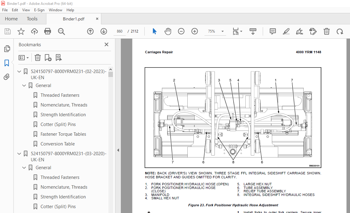
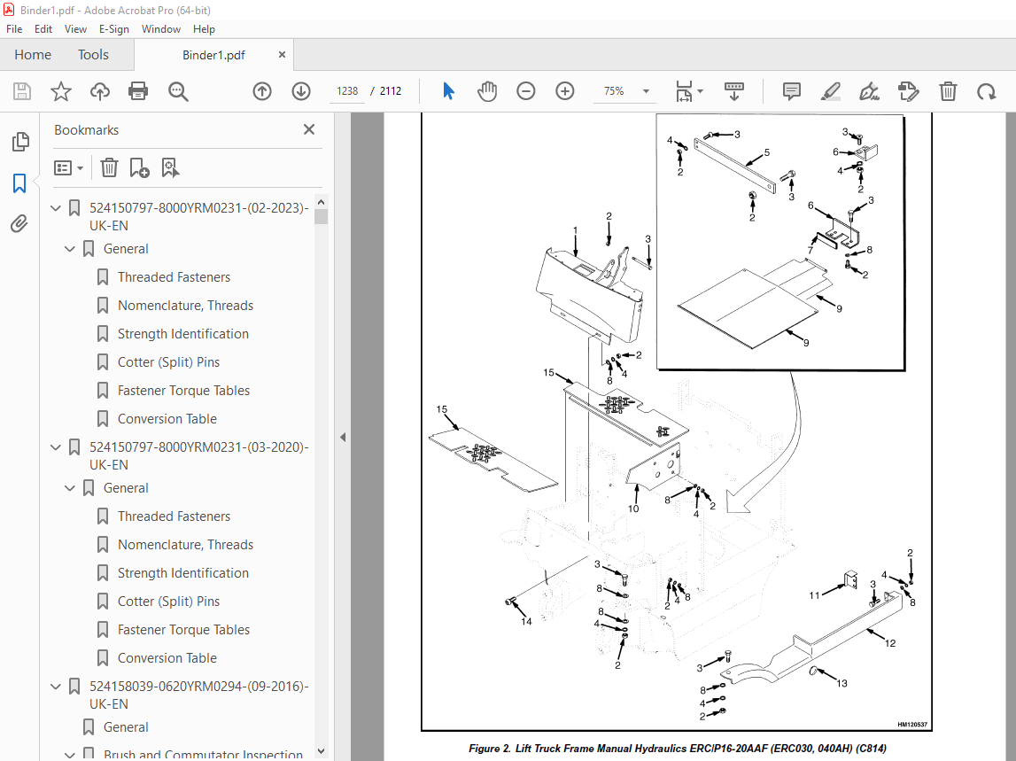
TABLE OF CONTENTS:
Yale Forklift C814 (ERCERP16AAF, ERCERP18AAF, ERCERP20AAF) Service Manual – PDF DOWNLOAD
524150797-8000YRM0231-(02-2023)-UK-EN 1
General 7
Threaded Fasteners 7
Nomenclature, Threads 7
Strength Identification 8
Cotter (Split) Pins 9
Fastener Torque Tables 14
Conversion Table 16
524150797-8000YRM0231-(03-2020)-UK-EN 23
General 27
Threaded Fasteners 27
Nomenclature, Threads 27
Strength Identification 28
Cotter (Split) Pins 29
Fastener Torque Tables 34
Conversion Table 36
524158039-0620YRM0294-(09-2016)-UK-EN 43
General 47
Brush and Commutator Inspection 48
Hydraulic Pump Motor and Traction Motor 48
Steering Pump Motor 51
Normal Commutator Surface 51
Commutator Problems 51
Brush Replacement 56
Stoning the Commutator 59
Motors Repair 60
Disassemble 61
Traction Motor and Hydraulic Pump Motor 61
Steering Pump Motor 62
Assemble 66
Traction Motor and Hydraulic Pump Motor 66
Steering Pump Motor 68
Brush Alignment, Traction and Hydraulic Motors 70
Tests for Damaged Field and Armature 71
Test for an Open Circuit in One Armature Winding 71
Test for Short Circuit in One Armature Winding 71
Test for Short Circuit to Armature Shaft 72
Test for Open Circuit in Field Coil 72
Test for Short Circuit in Field Coil 73
Test for Short Circuit Between Field and Motor Case 73
Brush Holder Test 73
Troubleshooting 74
524158040-2240YRM0001-(01-2023)-UK-EN 79
General 85
Battery Type 85
Lead-Acid Batteries 85
Lithium-Ion Batteries 86
Specific Gravity 86
Chemical Reaction in a Cell 86
Electrical Terms 88
Battery Selection 89
Battery Voltage 90
Battery as a Counterweight 90
Battery Ratings 90
Kilowatt-Hours 90
Battery Maintenance 91
Safety Procedures 91
Maintenance Records 91
New Battery 91
Cleaning Battery 92
Adding Water to Battery 94
Hydrometer 94
Battery Temperature 95
Charging Battery 96
Types of Battery Charges 97
Methods of Charging 98
Troubleshooting Charger 99
Knowing When Battery Is Fully Charged 99
Where to Charge Batteries 99
Equipment Needed 99
Battery Connectors 100
Battery Care 100
Troubleshooting 102
524158040-2240YRM0001-(03-2020)-UK-EN 107
General 111
Battery Type 111
Lead-Acid Batteries 111
Lithium-Ion Batteries 112
Specific Gravity 112
Chemical Reaction in a Cell 112
Electrical Terms 114
Battery Selection 114
Battery Voltage 115
Battery as a Counterweight 116
Battery Ratings 116
Kilowatt-Hours 116
Battery Maintenance 116
Safety Procedures 116
Maintenance Records 117
New Battery 117
Cleaning Battery 117
Adding Water to Battery 119
Hydrometer 120
Battery Temperature 121
Charging Battery 122
Types of Battery Charges 122
Methods of Charging 124
Troubleshooting Charger 124
Knowing When Battery Is Fully Charged 125
Where to Charge Batteries 125
Equipment Needed 125
Battery Connectors 126
Battery Care 126
Troubleshooting 128
524158753-1600YRM0720-(11-2006)-UK-EN 133
toc 133
Steering Housing and Control Unit 133
Safety Precautions Maintenance and Repair 134
General 137
Description 137
Operation 138
Steering Wheel and Column Assembly Repair 139
Assembly Components, Remove 139
Steering Control Unit, Disassemble 144
Steering Control Unit, Clean 144
Steering Control Unit, Assemble 144
Assembly Components, Install 146
System Air Removal 148
Troubleshooting 148
524158890-4000YRM0521-(03-2006)-UK-EN 153
toc 153
Mast 153
Safety Precautions Maintenance and Repair 154
General 157
Description and Operation 157
Carriages 157
Mast Mounts 159
Two-Stage Mast, Limited Free-Lift (LFL) 160
Description and Operation 160
Two-Stage Mast, Full Free-Lift (FFL) 162
Description and Operation 162
Three-Stage Mast, Full Free-Lift (FFL) 164
Description and Operation 164
Four-Stage Mast 166
Description and Operation 166
Cylinder Cushion During Lifting Sequence 170
Cylinder Cushion During Lowering Sequence 171
524179936-0100YRM0617-(03-2006)-UK-EN 175
toc 175
Frame 175
Safety Precautions Maintenance and Repair 176
General 179
Description 179
Main Frame 179
Other Frame Weldments 189
Overhead Guard 190
Overhead Guard Replacement 195
Remove 195
Install 196
Battery and Operator Restraint System, Hood and Seat Brake, and 196
Battery Restraint System 196
Hood and Seat Brake 198
Hood With E-Hydraulics 199
Operator Restraint System and Seat Assembly 200
Automatic Locking Retractor (ALR) 200
Emergency Locking Retractor (ELR) 200
Counterweight Replacement 201
Remove 201
Install 203
Traction Motor Replacement 204
Remove 204
Install 206
Hydraulic Tank Repair 207
Inspect 207
Clean 208
Steam Method 208
Chemical Solution Method 208
Additional Preparations for Repair 209
Small Leaks, Repair 209
Large Leaks, Repair 209
Preparations for Usage After Repair 209
Painting Instructions 209
Safety Label Replacement 211
Battery Specifications 213
tables 175
Table 1 Counterweights 202
524179939-1400YRM0618-(03-2006)-UK-EN 217
toc 217
Drive Axle, Speed Reducer, and Differential 217
Safety Precautions Maintenance and Repair 218
General 221
Description 221
Drive Unit Assembly Repair 221
Remove Complete Drive Unit Assembly as a Unit 221
Traction Motor, Remove 222
Drive Unit and Speed Reducer, Remove 224
Drive Axle, Disassemble 225
Differential and Speed Reducer, Disassemble 225
Clean 228
Inspect 228
Assembly of Drive Unit 228
Find Correct Shim Set for Hypoid Gear 228
Pinion, Assemble and Install 229
Differential and Ring Gear, Assemble and Install 230
Input Gear for Speed Reducer, Assemble 234
Drive Axle and Hub Assembly, Assemble 235
Installation of Drive Unit 236
Drive Unit, Install 236
Traction Motor, Install 237
Torque Specifications 238
Troubleshooting 239
tables 217
Table 1 Shims Adjustment for Pinion 229
Table 2 Ring and Pinion Tooth Contact Adjustment 233
524179940-1600YRM0619-(03-2006)-UK-EN 243
toc 243
Steering Axle 243
Safety Precautions Maintenance and Repair 244
General 247
Description 247
Steering Axle Assembly Repair 248
Remove 248
Install 248
Wheels and Hubs Repair 249
Remove and Disassemble 249
Clean 249
Assemble and Install 249
Spindles, Bearings, and Links Repair 253
Remove and Disassemble; Lift Truck Models ERC/P16-20AAF (A814/B8 253
Clean 253
Assemble and Install; Lift Truck Models ERC/P16-20AAF (A814/B814 253
Remove and Disassemble; Lift Truck Models ERC030-040AF and ERC03 255
Clean 255
Inspect 255
Assemble and Install; Lift Truck Models ERC030-040AF and ERC030- 255
Steering Cylinder Repair 257
Remove and Disassemble 257
Clean and Inspect 257
Assemble and Install 257
Torque Specifications 258
Troubleshooting 259
524179944-1800YRM0620-(03-2008)-UK-EN 263
toc 263
Brake System 263
Safety Precautions Maintenance and Repair 264
General 267
Description and Operation 267
Service Brakes 267
Master Cylinder 267
Parking Brake 269
Service Brakes Repair 269
Remove and Disassemble 269
Clean 272
Inspect 272
Assemble and Install 273
Master Cylinder Repair 276
Remove 276
Disassemble 277
Clean and Inspect 279
Assemble 279
Install 282
Parking Brake Repair 282
Remove and Dissemble 282
Assemble and Install 282
Parking Brake Switch Replacement 286
Brake System Air Removal 286
Service Brakes Adjustment 287
Brake Pedal Adjustment 287
Master Cylinder Adjustment 288
Parking Brake Adjustment 288
Parking Brake Switch Adjustment 288
Parking Brake Not Applied Switch Test 288
Seat Brake Assembly 288
Seat Brake, Adjust – Lift Truck Models ERC/P16-20AAF (ERC030-040 288
Brake Switch, Adjust – Lift Truck Models ERC/P16-20AAF (ERC030-0 289
Electric Seat Brake Without Handle, Adjust for Lift Truck Model 290
Electric Seat Brake With Handle for Lift Truck Model ERC/P16-20A 291
Remove 291
Clean 291
Inspect 291
Install 293
Adjustments 293
Solenoid Adjustment 293
Traction cutoff Switch Adjustment 293
Cable Adjustment 294
Torque Specifications 296
Troubleshooting 296
524179945-1900YRM0559-(04-2009)-UK-EN 303
toc 303
Hydraulic System 303
Safety Precautions Maintenance and Repair 304
General 307
Description 307
Hydraulic System 307
Operation 315
Hydraulic System 315
Hydraulic Gear Pump 321
Steering Pump 321
Hydraulic Tank Repair 329
Tank, Remove [ERC/P16-20AAF (ERC030-040AF, AG/BG) (A814); ERC/P1 329
Tank, Remove [ERP20-30ALF (B216) and ERP20-30ALF (ERP040-060DH) 331
Tank, Remove [ERP20-32ALF (ERP040-065DH) (E216)] 332
Hydraulic Tank [ERC35-55HG (ERC70-120HH) (B839/C839)] 332
Inspect 333
Small Leaks, Repair 334
Large Leaks, Repair 334
Clean 334
Steam Method 334
Chemical Solution Method 335
Additional Methods for Tank Repair 335
Tank, Install [ERC/P16-20AAF (ERC030-040AF, AG/BG) (A814); ERC/P 335
Tank, Install [ERP20-30ALF (B216) and ERP20-30ALF (ERP040-060DH) 336
Tank, Install [ERP20-32ALF (ERP040-065DH) (E216)] 336
Filter Replacement 337
All Lift Trucks Except [ERC35-55HG (ERC70-120HH) (B839/C839); ER 337
Remove 337
Install 338
Lift Truck Models [ERC35-55HG (ERC70-120HH) (B839/C839)] 338
Remove 338
Install 338
Lift truck Models [ERC20-32AGF (ERC040-065GH) (A908) and ERC/P16 339
Remove 339
Install 339
Lift Truck Models [ERP20-32ALF (ERP040-065DH) (E216)] 341
Remove 341
Install 341
Hydraulic Pump Repair 344
Hydraulic Pump, Remove [ERC/P16-20AAF (ERC030-040AF, AG/BG) (A81 344
Hydraulic Pump, Disassemble ERC/P16-20AAF (ERC030-040AF, AG/BG) 344
Inspect 346
Clean 346
Pump Seal Replace and Pump Assemble 346
Assemble Pump on Motor 346
Hydraulic Pump and Motor, Install [ERC/P16-20AAF (ERC030-040AF, 348
Hydraulic Pump, Remove [ERP20-30ALF (B216); ERP20-30ALF (ERP040- 349
Hydraulic Pump, Disassemble [ERC35-55HG (ERC70-120HH) (B839/C839 350
Hydraulic Pump, Inspect [ERC35-55HG (ERC70-120HH) (B839/C839) an 352
Hydraulic Pump, Clean [ERC35-55HG (ERC70-120HH) (B839/C839) and 352
Hydraulic Pump, Assemble [ERC35-55HG (ERC70-120HH) (B839/C839) a 352
Hydraulic Pump and Motor, Install [ERP20-30ALF (B216); ERP20-30A 352
Main Control Valve Repair 354
Steering Pump Repair 354
Pump, Remove and Disassemble [ERC/P16-20AAF (ERC030-040AF, ERC03 354
Pump, Remove and Disassemble [ERP20-30ALF (B216); ERP20-30ALF (E 356
Pump, Assemble and Install 358
Steering Control Unit Replacement 359
Remove 359
Install 359
Steering Cylinder Repair 365
Main Control Valve Check and Adjust 365
Steering Relief Valve Check and Adjust 366
Specifications 366
Relief Valve Pressures* 366
Hydraulic Tank Capacity (dipstick full mark) 367
Hydraulic Pump Capacities – All Models Except ERC35-55HG (ERC70- 367
Hydraulic Pump Capacities – Models ERC35-55HG (ERC70-120HH) (B83 367
Troubleshooting 367
Steering 367
Steering Housing and Steering Control Unit 368
Hydraulic System 369
524179946-2000YRM0562-(02-2009)-UK-EN 375
toc 375
Manual hydraulic Control Valve 375
Safety Precautions Maintenance and Repair 376
General 379
Description 379
Operation 382
ERC/P16-20AAF (ERC030-040AF, AG/BG) (A814); ERC/P16-20AAF (ERC03 382
ERP20-30ALF (B216), ERP20-30ALF (ERP040-060DH) (D216) and ERP20- 382
Lift Section 384
Tilt Section 384
Tilt Backward 384
Tilt Forward 384
Relief Valve 386
Main Control Valve Repair 387
Main Control Valve Without OPS Solenoid 387
Remove 387
Disassemble 387
Clean and Inspect 391
Assemble 391
Install [ERC/P16-20AAF (ERC030-040AF, AG/BG) (A814); ERC/P16-20A 392
Install [ERP20-30ALF (B216), ERP20-30ALF (ERP040-060DH) (D216) a 392
Main Control Valve With OPS Solenoid 393
Remove 393
Disassemble 393
Clean and Inspect 395
Relief Valve Repair 397
Assemble 398
Install 399
Control Lever Linkage Repair 399
Remove [ERC/P16-20AAF (ERC030-040AF, AG/BG) (A814),ERC/P16-20AAF 399
Disassemble [ERC/P16-20AAF (ERC030-040AF, AG/BG) (A814),ERC/P16- 399
Assemble and Install [ERC/P16-20AAF (ERC030-040AF, AG/BG) (A814) 401
Control Valve Linkage Repair 401
Remove and Disassemble [ERC/P16-20AAF (ERC030-040AF, AG/BG) (A81 401
Assemble and Install [ERC/P16-20AAF (ERC030-040AF, AG/BG) (A814) 402
Control Lever Linkage Repair 402
Remove [ERP20-30ALF (B216), ERP20-30ALF (ERP040-060DH) (D216) an 402
Disassemble [ERP20-30ALF (B216), ERP20-30ALF (ERP040-060DH) (D21 404
Assemble and Install [ERP20-30ALF (B216), ERP20-30ALF (ERP040-06 404
Pressure Relief Valve Check and Adjustment 405
Primary Relief Valve 405
Secondary Relief Valve 406
Troubleshooting 407
524183081-1600YRM1054-(11-2006)-UK-EN 411
toc 411
Steering System for AC Electric Lift Trucks 411
Safety Precautions Maintenance and Repair 412
General 415
Description 416
Steering Wheel and Column Assembly Repair 417
General 417
Assembly Components, Remove 419
Assembly Components, Install 420
Power Steering Motor and Pump 421
Description 421
Remove 421
Disassemble 424
Install 424
Power Steering Pump, Repair 424
Seal, Replace 425
Steering System Air Removal 426
Steering Pressure Check 426
Steering Motor Circuits Check 427
Troubleshooting 428
524183082-2200YRM1055-(10-2009)-UK-EN 433
toc 433
Electrical System (Trucks With AC Controllers) 433
Safety Precautions Maintenance and Repair 434
General 437
Description 438
Features of the Display Panels 438
Other Control Components 439
Display Panel and Key Switch Replacement 440
Display Panel, Replace 440
Key Switch, Replace 442
Controller Replacement 442
Traction and Pump Motor Controller Replacement 442
Master Controller, Replace 448
Master Controller, Remove ERP20-30ALF (ERP040-060DH) (D216), ERP 448
Master Controller, Install ERP20-30ALF (ERP040-060DH) (D216), ER 448
Master Controller, Remove ERC/P16-20AAF (ERC030-040AH) (B814/C81 450
Master Controller, Install ERC/P16-20AAF (ERC030-040AH) (B814/C8 450
Master Controller, Remove ERC35-55HG (ERC070-120HH) (B839/C839) 452
Master Controller, Install ERC35-55HG (ERC070-120HH) (B839/C839) 452
Control Components Replacement 453
General 453
Start Switch, Replace 453
Brake Light Switch, Replace 454
Seat Switch, Replace 454
Parking Brake Switch, Replace 455
Foot Directional Control Pedal Direction Switches, Replace 457
Steering Column Direction Control Switches, Replace 460
Remove 460
Install 460
Brake Fluid Switch, Replace 462
Brush Wear and Over Temperature Sensors (DC Pump Motor Only) 462
Rocker Switches for Lights, Replace 462
Accelerator Position Sensor, Replace 463
On-Demand Steering Sensor, Replace 464
Lights, Converter, Relay, and Reverse Alarm 464
Brake, Tail, and Reverse Light Assembly, Replace 465
Incandescent Assembly 465
LED Assembly – Remove 467
LED Assembly – Install 467
Strobe Light Assembly, Replace 470
Wire Harness Repair 471
Del-City Crimp-Solder-Shrink Splice 471
Front, Rear Driving Light or Spot Light Assemblies, Replace 472
Converter, Replace 472
Remove, Lift Truck Models ERP20-30ALF (ERP040-060DH) (D216), ERP 472
Install, Lift Truck Models ERP20-30ALF (ERP040-060DH) (D216), ER 474
Remove, Lift Truck Models ERC20-32AGF (ERC040-065GH) (A908) and 474
Install, Lift Truck Models ERC20-32AGF (ERC040-065GH) (A908) and 474
Remove, Lift Truck Models ERC35-55HG (ERC70-120HH) (B839/C839) 476
Install, Lift Truck Models ERC35-55HG (ERC70-120HH) (B839/C839) 476
Reverse Relay, Replace 477
Lift Truck Models ERC20-32AGF (ERC040-065GH) (A908), ERC/P16-20A 477
Lift Truck Models ERC35-55HG (ERC70-120HH) (B839/C839) 477
Backup Alarm, Replace 479
Horn and Horn Button, Replace 479
Horn Replacement for Lift Trucks ERP20-30ALF (ERP040-060DH) (D21 479
Horn Replacement for Lift Trucks ERC35-55HG (ERC70-120HH) (B839/ 481
Horn Switch and Cover, Replace 482
Hydraulic Pump Switches 483
Fan Power Supply, Replace 483
Remove, Lift Truck Models ERC35-55HG (ERC70-120HH) (B839/C839) 483
Install, Lift Truck Models ERC35-55HG (ERC70-120HH) (B839/C839) 483
Remove, Lift Truck Models ERP20-30ALF (ERP040-060DH) (D216) and 484
Install, Lift Truck Models ERP20-30ALF (ERP040-060DH) (D216) and 485
Remove, Lift Truck Models ERC20-32AGF (ERC040-065GH) (A908) 485
Install, Lift Truck Models ERC20-32AGF (ERC040-065GH) (A908) 485
Control and Power Fuse Check 486
Fuse Locations 486
Brake Light Switch Adjustment 492
Seat Switch Check 493
Seat Brake Adjustment 493
Parking Brake Switch Adjustment 494
Direction Switches Check 494
Foot Directional Control Pedal 494
Steering Column 495
Foot Directional Control Pedal or Accelerator Pedal Adjustment 495
Accelerator Position Sensor Adjustment and Start Switch Adjustme 496
Acceleration Position Sensor, Adjust 496
Start Switch, Adjust 498
tables 433
Table 1 Wire Splice Size 471
524183083-2200YRM1056-(03-2009)-UK-EN 501
toc 501
AC Motor Controllers/Display Panel 501
Safety Precautions Maintenance and Repair 502
Description 505
General 505
AC Motors 505
Motor Controllers 505
Master Controller 505
Dash Display 505
Controller Area Network Bus (CANbus) 505
Master Controller Checks and Adjustments 506
Function Settings 507
General 507
Function Numbers 507
Function Descriptions 510
General 510
Function Number 1 BATTERY VOLTAGE 510
Function Number 2 EXTENDED SHIFT 510
Function Number 3 ACCELERATION 1 510
Function Number 4 ACCELERATION 2 510
Function Number 5 TOP SPEED LIMIT 510
Function Number 6 REGEN BRAKING 510
Function Number 7 AUTO DECELERATION 511
Function Number 8 BDI ADJUSTMENT 511
Function Number 9 LIFT INTERRUPT 511
Function Number 10 POWER STEERING TIME DELAY 511
Function Number 11 SERVICE REMINDER 511
Function Number 12 CUSTOM 511
Function Number 13 PUMP SPEED 1 511
Function Number 14 PUMP SPEED 2 512
Function Number 15 PUMP SPEED 3 512
Function Number 16 PUMP ACCELERATION 512
Troubleshooting 512
General 512
Controller Status Light Emitting Diodes (LEDs) 513
Master Controller 513
AC Motor Controllers 513
Status Codes 519
AC Motor Controllers Status Code Charts 521
Troubleshooting When Dash and/or Lift Truck is not Operational 542
Typical Symptoms 542
Truck Runs but Dash Display is not Operational, or Only Displays 542
Truck Does Not Run and Dash is Not Operational or Only Displays 543
Hydraulics Operate Normally, Traction Does Not Operate Correctly 544
Traction Operates Normally, Hydraulics do Not Operate Correctly, 544
AC Transistor Motor Controller Replacement 544
General 544
General Maintenance Instructions 550
Special Precautions 550
Fuses 551
Fan Test 551
Contactors 551
Repair 551
Thermal Sensors 555
Motor Controller, Replace 555
Display Panel 556
General 556
Premium Display Panel 556
Standard Display Panel 556
Display Functions and Features 557
Key-On Initialization 557
Standard Display 558
Premium Display 558
Lift Truck Inspection Function 559
Access to Service Functions 559
Service Functions 559
Service Functions 560
Performance Modes 562
Battery Discharge Indicator (BDI) 562
Hourmeter 563
Dash Display Service Menu Navigation 569
General 569
Moving Through Menu Selections 569
Editing and Adding Information 569
tables 501
Table 1 Factory Parameters for ERP20-30ALF (ERP040-060DH) (D216 507
Table 2 Factory Setting for ERC020-032AGF (ERC40-65GH) (A908) 508
Table 3 Factory Setting for ERC/P16-20AAF (ERC030-040AH) (B814/ 508
Table 4 Factory Parameters for ERC35-55HG (ERC70-120HH) (B839/C 509
Table 5 List of Status Codes 519
Table 6 42-Pin Connections/Descriptions for Master Controller 552
Table 7 Pin Connections/Descriptions for 72/80 (Gen IV) Volt Mo 554
Table 8 Pin Connections/Descriptions for 36/48 and 72v/80v (Gen 554
524183085-2200YRM1058-(04-2011)-UK-EN 573
toc 573
Troubleshooting and Adjustments Using the AC Controls Program (E 573
Safety Precautions Maintenance and Repair 574
General 577
Computer Requirements 577
Software, Install 577
Language Selection 577
Demo Mode 578
Connect PC to Lift Truck 582
Starting AC Controls Program 584
Lift Truck Control Setup 589
Change Lift Truck Serial Number or Hourmeter 589
Setting Factory Default Values or Changing Lift Truck Parameters 590
Create New Custom Lift Truck Configuration 596
Lift Truck Configuration Properties 599
Import New Lift Truck Configuration From Disk 602
Delete Custom Lift Truck Configuration or Password File 604
Dash Display 607
Custom Display Languages 607
Download Display Language 609
Clear Operator Log 609
Password Functions 612
Enable/Disable Password and Lift Truck Inspection Functions 612
Truck Inspection Checklist 612
Password 612
Password Properties 612
Create New Password File 617
Download Passwords 618
Upload Passwords 620
Reports Menu 622
Devices Report 622
Custom Report 622
Password Report 622
Operator Report 629
Current Settings Report 632
Status Code Report 636
Status Codes Log 639
Troubleshooting 641
Diagnostics 641
Help Menu 644
General 644
Contents 644
Technical Support 644
About Electric Truck AC Controls Program 644
524183086-8000YRM1059-(08-2012)-UK-EN 651
toc 651
Electrical Diagrams 651
Safety Precautions Maintenance and Repair 652
524183087-8000YRM1060-(02-2010)-UK-EN 727
toc 727
Periodic Maintenance 727
Safety Precautions Maintenance and Repair 728
General 733
Serial Number Data 733
How to Move Disabled Lift Truck 733
How to Tow Lift Truck 733
How to Put Lift Truck on Blocks 734
How to Raise Drive Tires 734
How to Raise Steering Tires 734
How to Clean a Lift Truck 734
Maintenance Schedule 736
Maintenance Procedures Every 8 Hours or Daily 743
How to Make Checks With Key OFF 743
Tires and Wheels 743
Forks 744
Inspect 744
Mast and Lift Chains, Inspect 745
Safety Labels 745
Steering Column Latch 745
Operator Restraint System 746
Automatic Locking Retractor (ALR) 746
Emergency Locking Retractor (ELR) 746
Battery Restraint System ERC20-32AGF (ERC040-065GH) (A908) and E 747
Battery Restraint System ERP20-30ALF (ERP040-060DH) (D216) Lift 748
Battery 748
Attachment 749
Hydraulic System 749
How to Make Checks With Key ON 750
Horn, Lights, and Alarm 750
Steering System 750
Service Brakes 750
Parking Brake 750
Control Levers and Pedals 751
Direction and Speed Control Pedals 751
Lift System Operation 751
Oil Leaks 751
First Service After First 100 Hours of Operation 751
Change Filter for Hydraulic Oil 751
Maintenance Procedures Every 250 Hours or 6 Weeks 753
Steering King Pins ERC/P16-20AAF (B814/C814) Trucks Only 753
Steering Tie Rods and Spindles 753
Maintenance Procedures Every 500 Hours or 3 Months 753
Differential and Speed Reducer ERC20-32AGF (ERC040-065GH) (A908) 753
Wheel Nut Torques 754
Header Hose Checks 754
Mast Lubrication 754
Forks 758
Remove 758
Inspect 758
Install 758
Adjust 759
Brake Fluid ERC/P16-20AAF (ERC030-040AH) (B814/C814) and ERC20-3 759
Parking Brake Adjustment 759
Seat Brake Operations Check 760
Maintenance Procedures Every 1000 Hours or 6 Months 760
Lift Chains 760
Wear Check 760
Lift Chain Lubrication 761
Forks 761
Check Upper and Lower Bearings, Integral Sideshift Carriage 761
Steering King Pins ERC20-32AGF (ERC040-065GH) (A908) Lift Truck 762
Steering Tie Rods ERP20-30ALF (ERP040-060DH) (D216) Lift Truck M 762
Steering Axle Spindles 762
King Pins ERP20-30ALF (ERP040-060DH) (D216) 762
Hydraulic Tank Breather 762
ERP20-30ALF (ERP040-060DH) (D216) 762
ERC20-32AGF (ERC040-065GH) (A908) 763
ERC/P16-20AAF (ERC030-040AH) (B814/C814) 763
Differential and Speed Reducer ERP20-30ALF (ERP040-060DH) (D216) 763
Brake Fluid ERP20-30ALF (ERP040-060DH) (D216) Lift Truck Models 764
Other Lubrication 764
Electrical Inspection 764
Contactors 764
Motor Brushes (DC Pump) 764
Motor Brushes, General 764
Maintenance Procedures Every 2000 Hours or Yearly 768
Hydraulic System 768
Change Filter for Hydraulic Oil 768
Change Hydraulic Oil 769
Differential and Speed Reducer 769
Brake Fluid Replacement 770
Service Brakes 770
Steering Tie Rods and Spindle Lift Truck Models ERC030-040AH (B8 770
Wheel Bearings 771
Steer Wheels, Lubrication 771
Drive Wheels, Lubrication 771
Lift Chains 771
Forks 771
Replace Upper and Lower Bearings, Integral Sideshift Carriage 771
Other Lubrication 771
Battery Maintenance 772
How to Charge Battery 772
How to Change Battery for ERP20-30ALF (ERP040-060DH) (D216) and 773
General 773
How to Change Battery for ERC20-32AGF (ERC040-065GH) (A908) and 775
General 775
Lift and Tilt System Leak Check 778
Lift Cylinders Leak Check 778
Tilt Cylinders Leak Check 779
Safety Procedures When Working Near Mast 779
WHEN WORKING NEAR THE MAST ALWAYS: 779
Lift Chain Adjustments 782
Welding Repairs 783
Overhead Guard Changes 783
Wheels and Tire Maintenance 784
Solid Rubber Tires ERC20-32AGF (ERC040-065GH) (A908) and ERC/P16 784
Remove Wheels From Lift Truck 784
Remove and Install Tire on Wheel 784
Pneumatic Tires and Wheels ERP20-30ALF (ERP040-060DH) (D216) 785
Remove Wheels From Lift Truck 785
Remove Wheel From Pneumatic Tire 786
Install Three- or Four-Piece Wheel in Pneumatic Tire 787
Add Air to Tires 788
Wheels, Install 788
Solid Rubber Tires on Pneumatic Wheels 789
Remove Wheels From Lift Truck 789
Remove Solid Rubber Tire From Pneumatic Wheel 789
Install Solid Rubber Tire on Pneumatic Wheel 791
Wheels, Install 792
Snap-On Tire, Change 792
Remove Snap-On Solid Tire From Wheel 793
Install Snap-On Solid Tire on Wheel 794
Adhesives and Sealants 795
tables 727
Table 1 Maintenance Schedule 738
524205680-0620YRM1098-(03-2010)-UK-EN 799
toc 799
AC Motor Repair 799
Safety Precautions Maintenance and Repair 800
General 803
AC Motor Repair 803
Disassemble 803
Assemble 807
Troubleshooting 809
524213865-8000YRM1113-(02-2009)-UK-EN 813
toc 813
Capacities and Specifications 813
Safety Precautions Maintenance and Repair 814
Wheels and Tires 817
Counterweights 817
Hydraulic System 817
Capacities 818
Battery Specifications 819
Battery Height Specifications (Hoods and Battery Types) 820
Maximum Carriage and Tilt Creep Rates 821
Mast Speeds 821
ERC030AH, ERC040AH, Mast Speeds (36 and 48 Volt) Americas 821
ERC/P16-20AAF Mast Speeds (48 Volt) Europe 822
Torque Specifications 823
Frame 823
Mast 823
Drive Axle, Speed Reducer, and Differential 824
Steering Axle 824
Brake 824
E-Hydraulic Control Valve 824
Adhesives and Sealants 825
tables 813
Table 1 Manual Control Valve 817
Table 2 E-Hydraulic Control Valve 818
524223776-4000YRM1148-(09-2015)-UK-EN 829
General 833
Safety Procedures When Working Near Mast 834
Fork Replacement 836
Remove, Lift Trucks Not Equipped With Fork Positioner Or Equipped With Fork Positioner Before August, 2012 836
Remove, Lift Trucks Manufactured After August, 2012 And Equipped With Fork Positioner 838
Install, Lift Trucks Not Equipped With Fork Positioner Or Equipped With Fork Positioner Before August, 2012 839
Install, Lift Trucks Manufactured After August, 2012 And Equipped With Fork Positioner 839
Checks, Lift Trucks Not Equipped With Fork Positioner Or Equipped With Fork Positioner Before August, 2012 840
Checks, Lift Trucks Manufactured After August, 2012 And Equipped With Fork Positioner 841
Carriages Repair 842
Standard Carriage 842
Remove 842
Repair 843
Install 843
Standard Carriage, Remove 844
Hang-On Sideshift Carriage, Remove 845
Standard Carriage and Hang-On Sideshift Carriage, Repair 846
Standard Carriage, Install 847
Hang-On Sideshift Carriage, Install 847
Integral Sideshift Carriage 848
Remove 848
Clean and Inspect 851
Repair 852
Install 852
Fork Positioner 853
Remove 853
Clean and Inspect 858
Disassemble and Assemble 858
Install 858
Fork Positioner Hydraulic Hose Adjustment 859
Disconnecting Attachment Hydraulic Quick Disconnect Hoses 861
Connecting Attachment Hydraulic Quick Disconnect Hoses 861
Mast Repair 862
Mast, Remove 862
Two-Stage LFL and Two-Stage FFL Masts 865
Disassemble 865
Clean and Inspect 875
Three-Stage FFL Mast 876
Disassemble 876
Clean and Inspect 884
Two-Stage LFL and Two-Stage FFL Mast 886
Assemble 886
Three-Stage FFL Mast 889
Assemble 889
Four-Stage FFL Mast – Manufactured Before July, 2009 891
Disassemble 891
Clean and Inspect 896
Assemble 898
Four-Stage FFL Mast – Manufactured After July, 2009 899
Disassemble 899
Clean and Inspect 906
Assemble 909
Mast, Install 910
Header Hose Arrangement 913
Two-Stage LFL 913
Two-Stage FFL 921
Three-Stage FFL 936
Standard 936
Optional Equipment Lift Truck GLP/GDP20-35VX (GP/GLP/GDP040-070VX) (B875) 953
Four-Stage FFL Mast – Manufactured Before July, 2009 961
Four-Stage FFL Mast – Manufactured After July, 2009 970
Adjustment 977
Lift Chains Adjustment 977
Carriage Adjustments 980
Mast Adjustments 980
Load Roller Adjustment 980
Mast Side Kicking Adjustment 983
524256687-2000YRM1224-(04-2008)-UK-EN 987
toc 987
Electro-hydraulic Control Valve 987
Safety Precautions Maintenance and Repair 988
General 991
Description 991
Electro-Hydraulic Control System 991
Electro-Hydraulic Control Valve 994
Electro-Hydraulic Valve Driver Module 1010
Mini-Lever Module (MLM) 1010
Joystick 1011
Electro-Hydraulic Control Valve Repair 1012
Remove 1012
Disassemble 1021
Solenoid Coil Replacement 1023
Cartridge Replacement 1025
Electro-Hydraulic Pressure Reducing Valve (EHPR) Replacement 1026
Lift Circuit Check Valve Replacement 1027
Compensator Cartridge Replacement 1027
Primary and Secondary Relief Valves Replacement 1027
Tilt Counterbalance Valve Replacement 1028
Flow Regulator Valve Replacement 1028
Assemble 1028
Install 1028
E-Hydraulics Calibration 1037
Mini-Lever Module 1039
Mini-Lever Module (MLM) 1039
Remove 1039
Install 1039
Mini-Lever Replacement 1039
Remove 1039
Clean and Inspect 1040
Install 1040
Push Button Switch Replacement 1041
Remove 1041
Install 1042
Test 1043
Mini-levers 1043
Full Stroke Test 1043
Function Returns to Neutral Test 1043
Push Button Switch 1044
Joystick 1044
Remove and Disassemble 1044
Inspect 1044
Assemble and Install 1044
Troubleshooting 1045
tables 987
Table 1 Primary and Secondary Relief Valve Values 997
Table 2 Solenoid Resistance Values 1023
Table 3 Cartridge and Solenoid Coil Nut Torque for Lift truck M 1026
Table 4 Cartridge and Solenoid Coil Nut Torque for Lift truck M 1026
Binder1 1057
524150797-8000YRM0231-(02-2023)-UK-EN 1057
General 1063
Threaded Fasteners 1063
Nomenclature, Threads 1063
Strength Identification 1064
Cotter (Split) Pins 1065
Fastener Torque Tables 1070
Conversion Table 1072
524150797-8000YRM0231-(03-2020)-UK-EN 1079
General 1083
Threaded Fasteners 1083
Nomenclature, Threads 1083
Strength Identification 1084
Cotter (Split) Pins 1085
Fastener Torque Tables 1090
Conversion Table 1092
524158039-0620YRM0294-(09-2016)-UK-EN 1099
General 1103
Brush and Commutator Inspection 1104
Hydraulic Pump Motor and Traction Motor 1104
Steering Pump Motor 1107
Normal Commutator Surface 1107
Commutator Problems 1107
Brush Replacement 1112
Stoning the Commutator 1115
Motors Repair 1116
Disassemble 1117
Traction Motor and Hydraulic Pump Motor 1117
Steering Pump Motor 1118
Assemble 1122
Traction Motor and Hydraulic Pump Motor 1122
Steering Pump Motor 1124
Brush Alignment, Traction and Hydraulic Motors 1126
Tests for Damaged Field and Armature 1127
Test for an Open Circuit in One Armature Winding 1127
Test for Short Circuit in One Armature Winding 1127
Test for Short Circuit to Armature Shaft 1128
Test for Open Circuit in Field Coil 1128
Test for Short Circuit in Field Coil 1129
Test for Short Circuit Between Field and Motor Case 1129
Brush Holder Test 1129
Troubleshooting 1130
524158040-2240YRM0001-(01-2023)-UK-EN 1135
General 1141
Battery Type 1141
Lead-Acid Batteries 1141
Lithium-Ion Batteries 1142
Specific Gravity 1142
Chemical Reaction in a Cell 1142
Electrical Terms 1144
Battery Selection 1145
Battery Voltage 1146
Battery as a Counterweight 1146
Battery Ratings 1146
Kilowatt-Hours 1146
Battery Maintenance 1147
Safety Procedures 1147
Maintenance Records 1147
New Battery 1147
Cleaning Battery 1148
Adding Water to Battery 1150
Hydrometer 1150
Battery Temperature 1151
Charging Battery 1152
Types of Battery Charges 1153
Methods of Charging 1154
Troubleshooting Charger 1155
Knowing When Battery Is Fully Charged 1155
Where to Charge Batteries 1155
Equipment Needed 1155
Battery Connectors 1156
Battery Care 1156
Troubleshooting 1158
524158040-2240YRM0001-(03-2020)-UK-EN 1163
General 1167
Battery Type 1167
Lead-Acid Batteries 1167
Lithium-Ion Batteries 1168
Specific Gravity 1168
Chemical Reaction in a Cell 1168
Electrical Terms 1170
Battery Selection 1170
Battery Voltage 1171
Battery as a Counterweight 1172
Battery Ratings 1172
Kilowatt-Hours 1172
Battery Maintenance 1172
Safety Procedures 1172
Maintenance Records 1173
New Battery 1173
Cleaning Battery 1173
Adding Water to Battery 1175
Hydrometer 1176
Battery Temperature 1177
Charging Battery 1178
Types of Battery Charges 1178
Methods of Charging 1180
Troubleshooting Charger 1180
Knowing When Battery Is Fully Charged 1181
Where to Charge Batteries 1181
Equipment Needed 1181
Battery Connectors 1182
Battery Care 1182
Troubleshooting 1184
524158753-1600YRM0720-(11-2006)-UK-EN 1189
toc 1189
Steering Housing and Control Unit 1189
Safety Precautions Maintenance and Repair 1190
General 1193
Description 1193
Operation 1194
Steering Wheel and Column Assembly Repair 1195
Assembly Components, Remove 1195
Steering Control Unit, Disassemble 1200
Steering Control Unit, Clean 1200
Steering Control Unit, Assemble 1200
Assembly Components, Install 1202
System Air Removal 1204
Troubleshooting 1204
524158890-4000YRM0521-(03-2006)-UK-EN 1209
toc 1209
Mast 1209
Safety Precautions Maintenance and Repair 1210
General 1213
Description and Operation 1213
Carriages 1213
Mast Mounts 1215
Two-Stage Mast, Limited Free-Lift (LFL) 1216
Description and Operation 1216
Two-Stage Mast, Full Free-Lift (FFL) 1218
Description and Operation 1218
Three-Stage Mast, Full Free-Lift (FFL) 1220
Description and Operation 1220
Four-Stage Mast 1222
Description and Operation 1222
Cylinder Cushion During Lifting Sequence 1226
Cylinder Cushion During Lowering Sequence 1227
524179936-0100YRM0617-(03-2006)-UK-EN 1231
toc 1231
Frame 1231
Safety Precautions Maintenance and Repair 1232
General 1235
Description 1235
Main Frame 1235
Other Frame Weldments 1245
Overhead Guard 1246
Overhead Guard Replacement 1251
Remove 1251
Install 1252
Battery and Operator Restraint System, Hood and Seat Brake, and 1252
Battery Restraint System 1252
Hood and Seat Brake 1254
Hood With E-Hydraulics 1255
Operator Restraint System and Seat Assembly 1256
Automatic Locking Retractor (ALR) 1256
Emergency Locking Retractor (ELR) 1256
Counterweight Replacement 1257
Remove 1257
Install 1259
Traction Motor Replacement 1260
Remove 1260
Install 1262
Hydraulic Tank Repair 1263
Inspect 1263
Clean 1264
Steam Method 1264
Chemical Solution Method 1264
Additional Preparations for Repair 1265
Small Leaks, Repair 1265
Large Leaks, Repair 1265
Preparations for Usage After Repair 1265
Painting Instructions 1265
Safety Label Replacement 1267
Battery Specifications 1269
tables 1231
Table 1 Counterweights 1258
524179939-1400YRM0618-(03-2006)-UK-EN 1273
toc 1273
Drive Axle, Speed Reducer, and Differential 1273
Safety Precautions Maintenance and Repair 1274
General 1277
Description 1277
Drive Unit Assembly Repair 1277
Remove Complete Drive Unit Assembly as a Unit 1277
Traction Motor, Remove 1278
Drive Unit and Speed Reducer, Remove 1280
Drive Axle, Disassemble 1281
Differential and Speed Reducer, Disassemble 1281
Clean 1284
Inspect 1284
Assembly of Drive Unit 1284
Find Correct Shim Set for Hypoid Gear 1284
Pinion, Assemble and Install 1285
Differential and Ring Gear, Assemble and Install 1286
Input Gear for Speed Reducer, Assemble 1290
Drive Axle and Hub Assembly, Assemble 1291
Installation of Drive Unit 1292
Drive Unit, Install 1292
Traction Motor, Install 1293
Torque Specifications 1294
Troubleshooting 1295
tables 1273
Table 1 Shims Adjustment for Pinion 1285
Table 2 Ring and Pinion Tooth Contact Adjustment 1289
524179940-1600YRM0619-(03-2006)-UK-EN 1299
toc 1299
Steering Axle 1299
Safety Precautions Maintenance and Repair 1300
General 1303
Description 1303
Steering Axle Assembly Repair 1304
Remove 1304
Install 1304
Wheels and Hubs Repair 1305
Remove and Disassemble 1305
Clean 1305
Assemble and Install 1305
Spindles, Bearings, and Links Repair 1309
Remove and Disassemble; Lift Truck Models ERC/P16-20AAF (A814/B8 1309
Clean 1309
Assemble and Install; Lift Truck Models ERC/P16-20AAF (A814/B814 1309
Remove and Disassemble; Lift Truck Models ERC030-040AF and ERC03 1311
Clean 1311
Inspect 1311
Assemble and Install; Lift Truck Models ERC030-040AF and ERC030- 1311
Steering Cylinder Repair 1313
Remove and Disassemble 1313
Clean and Inspect 1313
Assemble and Install 1313
Torque Specifications 1314
Troubleshooting 1315
524179944-1800YRM0620-(03-2008)-UK-EN 1319
toc 1319
Brake System 1319
Safety Precautions Maintenance and Repair 1320
General 1323
Description and Operation 1323
Service Brakes 1323
Master Cylinder 1323
Parking Brake 1325
Service Brakes Repair 1325
Remove and Disassemble 1325
Clean 1328
Inspect 1328
Assemble and Install 1329
Master Cylinder Repair 1332
Remove 1332
Disassemble 1333
Clean and Inspect 1335
Assemble 1335
Install 1338
Parking Brake Repair 1338
Remove and Dissemble 1338
Assemble and Install 1338
Parking Brake Switch Replacement 1342
Brake System Air Removal 1342
Service Brakes Adjustment 1343
Brake Pedal Adjustment 1343
Master Cylinder Adjustment 1344
Parking Brake Adjustment 1344
Parking Brake Switch Adjustment 1344
Parking Brake Not Applied Switch Test 1344
Seat Brake Assembly 1344
Seat Brake, Adjust – Lift Truck Models ERC/P16-20AAF (ERC030-040 1344
Brake Switch, Adjust – Lift Truck Models ERC/P16-20AAF (ERC030-0 1345
Electric Seat Brake Without Handle, Adjust for Lift Truck Model 1346
Electric Seat Brake With Handle for Lift Truck Model ERC/P16-20A 1347
Remove 1347
Clean 1347
Inspect 1347
Install 1349
Adjustments 1349
Solenoid Adjustment 1349
Traction cutoff Switch Adjustment 1349
Cable Adjustment 1350
Torque Specifications 1352
Troubleshooting 1352
524179945-1900YRM0559-(04-2009)-UK-EN 1359
toc 1359
Hydraulic System 1359
Safety Precautions Maintenance and Repair 1360
General 1363
Description 1363
Hydraulic System 1363
Operation 1371
Hydraulic System 1371
Hydraulic Gear Pump 1377
Steering Pump 1377
Hydraulic Tank Repair 1385
Tank, Remove [ERC/P16-20AAF (ERC030-040AF, AG/BG) (A814); ERC/P1 1385
Tank, Remove [ERP20-30ALF (B216) and ERP20-30ALF (ERP040-060DH) 1387
Tank, Remove [ERP20-32ALF (ERP040-065DH) (E216)] 1388
Hydraulic Tank [ERC35-55HG (ERC70-120HH) (B839/C839)] 1388
Inspect 1389
Small Leaks, Repair 1390
Large Leaks, Repair 1390
Clean 1390
Steam Method 1390
Chemical Solution Method 1391
Additional Methods for Tank Repair 1391
Tank, Install [ERC/P16-20AAF (ERC030-040AF, AG/BG) (A814); ERC/P 1391
Tank, Install [ERP20-30ALF (B216) and ERP20-30ALF (ERP040-060DH) 1392
Tank, Install [ERP20-32ALF (ERP040-065DH) (E216)] 1392
Filter Replacement 1393
All Lift Trucks Except [ERC35-55HG (ERC70-120HH) (B839/C839); ER 1393
Remove 1393
Install 1394
Lift Truck Models [ERC35-55HG (ERC70-120HH) (B839/C839)] 1394
Remove 1394
Install 1394
Lift truck Models [ERC20-32AGF (ERC040-065GH) (A908) and ERC/P16 1395
Remove 1395
Install 1395
Lift Truck Models [ERP20-32ALF (ERP040-065DH) (E216)] 1397
Remove 1397
Install 1397
Hydraulic Pump Repair 1400
Hydraulic Pump, Remove [ERC/P16-20AAF (ERC030-040AF, AG/BG) (A81 1400
Hydraulic Pump, Disassemble ERC/P16-20AAF (ERC030-040AF, AG/BG) 1400
Inspect 1402
Clean 1402
Pump Seal Replace and Pump Assemble 1402
Assemble Pump on Motor 1402
Hydraulic Pump and Motor, Install [ERC/P16-20AAF (ERC030-040AF, 1404
Hydraulic Pump, Remove [ERP20-30ALF (B216); ERP20-30ALF (ERP040- 1405
Hydraulic Pump, Disassemble [ERC35-55HG (ERC70-120HH) (B839/C839 1406
Hydraulic Pump, Inspect [ERC35-55HG (ERC70-120HH) (B839/C839) an 1408
Hydraulic Pump, Clean [ERC35-55HG (ERC70-120HH) (B839/C839) and 1408
Hydraulic Pump, Assemble [ERC35-55HG (ERC70-120HH) (B839/C839) a 1408
Hydraulic Pump and Motor, Install [ERP20-30ALF (B216); ERP20-30A 1408
Main Control Valve Repair 1410
Steering Pump Repair 1410
Pump, Remove and Disassemble [ERC/P16-20AAF (ERC030-040AF, ERC03 1410
Pump, Remove and Disassemble [ERP20-30ALF (B216); ERP20-30ALF (E 1412
Pump, Assemble and Install 1414
Steering Control Unit Replacement 1415
Remove 1415
Install 1415
Steering Cylinder Repair 1421
Main Control Valve Check and Adjust 1421
Steering Relief Valve Check and Adjust 1422
Specifications 1422
Relief Valve Pressures* 1422
Hydraulic Tank Capacity (dipstick full mark) 1423
Hydraulic Pump Capacities – All Models Except ERC35-55HG (ERC70- 1423
Hydraulic Pump Capacities – Models ERC35-55HG (ERC70-120HH) (B83 1423
Troubleshooting 1423
Steering 1423
Steering Housing and Steering Control Unit 1424
Hydraulic System 1425
524179946-2000YRM0562-(02-2009)-UK-EN 1431
toc 1431
Manual hydraulic Control Valve 1431
Safety Precautions Maintenance and Repair 1432
General 1435
Description 1435
Operation 1438
ERC/P16-20AAF (ERC030-040AF, AG/BG) (A814); ERC/P16-20AAF (ERC03 1438
ERP20-30ALF (B216), ERP20-30ALF (ERP040-060DH) (D216) and ERP20- 1438
Lift Section 1440
Tilt Section 1440
Tilt Backward 1440
Tilt Forward 1440
Relief Valve 1442
Main Control Valve Repair 1443
Main Control Valve Without OPS Solenoid 1443
Remove 1443
Disassemble 1443
Clean and Inspect 1447
Assemble 1447
Install [ERC/P16-20AAF (ERC030-040AF, AG/BG) (A814); ERC/P16-20A 1448
Install [ERP20-30ALF (B216), ERP20-30ALF (ERP040-060DH) (D216) a 1448
Main Control Valve With OPS Solenoid 1449
Remove 1449
Disassemble 1449
Clean and Inspect 1451
Relief Valve Repair 1453
Assemble 1454
Install 1455
Control Lever Linkage Repair 1455
Remove [ERC/P16-20AAF (ERC030-040AF, AG/BG) (A814),ERC/P16-20AAF 1455
Disassemble [ERC/P16-20AAF (ERC030-040AF, AG/BG) (A814),ERC/P16- 1455
Assemble and Install [ERC/P16-20AAF (ERC030-040AF, AG/BG) (A814) 1457
Control Valve Linkage Repair 1457
Remove and Disassemble [ERC/P16-20AAF (ERC030-040AF, AG/BG) (A81 1457
Assemble and Install [ERC/P16-20AAF (ERC030-040AF, AG/BG) (A814) 1458
Control Lever Linkage Repair 1458
Remove [ERP20-30ALF (B216), ERP20-30ALF (ERP040-060DH) (D216) an 1458
Disassemble [ERP20-30ALF (B216), ERP20-30ALF (ERP040-060DH) (D21 1460
Assemble and Install [ERP20-30ALF (B216), ERP20-30ALF (ERP040-06 1460
Pressure Relief Valve Check and Adjustment 1461
Primary Relief Valve 1461
Secondary Relief Valve 1462
Troubleshooting 1463
524183081-1600YRM1054-(11-2006)-UK-EN 1467
toc 1467
Steering System for AC Electric Lift Trucks 1467
Safety Precautions Maintenance and Repair 1468
General 1471
Description 1472
Steering Wheel and Column Assembly Repair 1473
General 1473
Assembly Components, Remove 1475
Assembly Components, Install 1476
Power Steering Motor and Pump 1477
Description 1477
Remove 1477
Disassemble 1480
Install 1480
Power Steering Pump, Repair 1480
Seal, Replace 1481
Steering System Air Removal 1482
Steering Pressure Check 1482
Steering Motor Circuits Check 1483
Troubleshooting 1484
524183082-2200YRM1055-(10-2009)-UK-EN 1489
toc 1489
Electrical System (Trucks With AC Controllers) 1489
Safety Precautions Maintenance and Repair 1490
General 1493
Description 1494
Features of the Display Panels 1494
Other Control Components 1495
Display Panel and Key Switch Replacement 1496
Display Panel, Replace 1496
Key Switch, Replace 1498
Controller Replacement 1498
Traction and Pump Motor Controller Replacement 1498
Master Controller, Replace 1504
Master Controller, Remove ERP20-30ALF (ERP040-060DH) (D216), ERP 1504
Master Controller, Install ERP20-30ALF (ERP040-060DH) (D216), ER 1504
Master Controller, Remove ERC/P16-20AAF (ERC030-040AH) (B814/C81 1506
Master Controller, Install ERC/P16-20AAF (ERC030-040AH) (B814/C8 1506
Master Controller, Remove ERC35-55HG (ERC070-120HH) (B839/C839) 1508
Master Controller, Install ERC35-55HG (ERC070-120HH) (B839/C839) 1508
Control Components Replacement 1509
General 1509
Start Switch, Replace 1509
Brake Light Switch, Replace 1510
Seat Switch, Replace 1510
Parking Brake Switch, Replace 1511
Foot Directional Control Pedal Direction Switches, Replace 1513
Steering Column Direction Control Switches, Replace 1516
Remove 1516
Install 1516
Brake Fluid Switch, Replace 1518
Brush Wear and Over Temperature Sensors (DC Pump Motor Only) 1518
Rocker Switches for Lights, Replace 1518
Accelerator Position Sensor, Replace 1519
On-Demand Steering Sensor, Replace 1520
Lights, Converter, Relay, and Reverse Alarm 1520
Brake, Tail, and Reverse Light Assembly, Replace 1521
Incandescent Assembly 1521
LED Assembly – Remove 1523
LED Assembly – Install 1523
Strobe Light Assembly, Replace 1526
Wire Harness Repair 1527
Del-City Crimp-Solder-Shrink Splice 1527
Front, Rear Driving Light or Spot Light Assemblies, Replace 1528
Converter, Replace 1528
Remove, Lift Truck Models ERP20-30ALF (ERP040-060DH) (D216), ERP 1528
Install, Lift Truck Models ERP20-30ALF (ERP040-060DH) (D216), ER 1530
Remove, Lift Truck Models ERC20-32AGF (ERC040-065GH) (A908) and 1530
Install, Lift Truck Models ERC20-32AGF (ERC040-065GH) (A908) and 1530
Remove, Lift Truck Models ERC35-55HG (ERC70-120HH) (B839/C839) 1532
Install, Lift Truck Models ERC35-55HG (ERC70-120HH) (B839/C839) 1532
Reverse Relay, Replace 1533
Lift Truck Models ERC20-32AGF (ERC040-065GH) (A908), ERC/P16-20A 1533
Lift Truck Models ERC35-55HG (ERC70-120HH) (B839/C839) 1533
Backup Alarm, Replace 1535
Horn and Horn Button, Replace 1535
Horn Replacement for Lift Trucks ERP20-30ALF (ERP040-060DH) (D21 1535
Horn Replacement for Lift Trucks ERC35-55HG (ERC70-120HH) (B839/ 1537
Horn Switch and Cover, Replace 1538
Hydraulic Pump Switches 1539
Fan Power Supply, Replace 1539
Remove, Lift Truck Models ERC35-55HG (ERC70-120HH) (B839/C839) 1539
Install, Lift Truck Models ERC35-55HG (ERC70-120HH) (B839/C839) 1539
Remove, Lift Truck Models ERP20-30ALF (ERP040-060DH) (D216) and 1540
Install, Lift Truck Models ERP20-30ALF (ERP040-060DH) (D216) and 1541
Remove, Lift Truck Models ERC20-32AGF (ERC040-065GH) (A908) 1541
Install, Lift Truck Models ERC20-32AGF (ERC040-065GH) (A908) 1541
Control and Power Fuse Check 1542
Fuse Locations 1542
Brake Light Switch Adjustment 1548
Seat Switch Check 1549
Seat Brake Adjustment 1549
Parking Brake Switch Adjustment 1550
Direction Switches Check 1550
Foot Directional Control Pedal 1550
Steering Column 1551
Foot Directional Control Pedal or Accelerator Pedal Adjustment 1551
Accelerator Position Sensor Adjustment and Start Switch Adjustme 1552
Acceleration Position Sensor, Adjust 1552
Start Switch, Adjust 1554
tables 1489
Table 1 Wire Splice Size 1527
524183083-2200YRM1056-(03-2009)-UK-EN 1557
toc 1557
AC Motor Controllers/Display Panel 1557
Safety Precautions Maintenance and Repair 1558
Description 1561
General 1561
AC Motors 1561
Motor Controllers 1561
Master Controller 1561
Dash Display 1561
Controller Area Network Bus (CANbus) 1561
Master Controller Checks and Adjustments 1562
Function Settings 1563
General 1563
Function Numbers 1563
Function Descriptions 1566
General 1566
Function Number 1 BATTERY VOLTAGE 1566
Function Number 2 EXTENDED SHIFT 1566
Function Number 3 ACCELERATION 1 1566
Function Number 4 ACCELERATION 2 1566
Function Number 5 TOP SPEED LIMIT 1566
Function Number 6 REGEN BRAKING 1566
Function Number 7 AUTO DECELERATION 1567
Function Number 8 BDI ADJUSTMENT 1567
Function Number 9 LIFT INTERRUPT 1567
Function Number 10 POWER STEERING TIME DELAY 1567
Function Number 11 SERVICE REMINDER 1567
Function Number 12 CUSTOM 1567
Function Number 13 PUMP SPEED 1 1567
Function Number 14 PUMP SPEED 2 1568
Function Number 15 PUMP SPEED 3 1568
Function Number 16 PUMP ACCELERATION 1568
Troubleshooting 1568
General 1568
Controller Status Light Emitting Diodes (LEDs) 1569
Master Controller 1569
AC Motor Controllers 1569
Status Codes 1575
AC Motor Controllers Status Code Charts 1577
Troubleshooting When Dash and/or Lift Truck is not Operational 1598
Typical Symptoms 1598
Truck Runs but Dash Display is not Operational, or Only Displays 1598
Truck Does Not Run and Dash is Not Operational or Only Displays 1599
Hydraulics Operate Normally, Traction Does Not Operate Correctly 1600
Traction Operates Normally, Hydraulics do Not Operate Correctly, 1600
AC Transistor Motor Controller Replacement 1600
General 1600
General Maintenance Instructions 1606
Special Precautions 1606
Fuses 1607
Fan Test 1607
Contactors 1607
Repair 1607
Thermal Sensors 1611
Motor Controller, Replace 1611
Display Panel 1612
General 1612
Premium Display Panel 1612
Standard Display Panel 1612
Display Functions and Features 1613
Key-On Initialization 1613
Standard Display 1614
Premium Display 1614
Lift Truck Inspection Function 1615
Access to Service Functions 1615
Service Functions 1615
Service Functions 1616
Performance Modes 1618
Battery Discharge Indicator (BDI) 1618
Hourmeter 1619
Dash Display Service Menu Navigation 1625
General 1625
Moving Through Menu Selections 1625
Editing and Adding Information 1625
tables 1557
Table 1 Factory Parameters for ERP20-30ALF (ERP040-060DH) (D216 1563
Table 2 Factory Setting for ERC020-032AGF (ERC40-65GH) (A908) 1564
Table 3 Factory Setting for ERC/P16-20AAF (ERC030-040AH) (B814/ 1564
Table 4 Factory Parameters for ERC35-55HG (ERC70-120HH) (B839/C 1565
Table 5 List of Status Codes 1575
Table 6 42-Pin Connections/Descriptions for Master Controller 1608
Table 7 Pin Connections/Descriptions for 72/80 (Gen IV) Volt Mo 1610
Table 8 Pin Connections/Descriptions for 36/48 and 72v/80v (Gen 1610
524183085-2200YRM1058-(04-2011)-UK-EN 1629
toc 1629
Troubleshooting and Adjustments Using the AC Controls Program (E 1629
Safety Precautions Maintenance and Repair 1630
General 1633
Computer Requirements 1633
Software, Install 1633
Language Selection 1633
Demo Mode 1634
Connect PC to Lift Truck 1638
Starting AC Controls Program 1640
Lift Truck Control Setup 1645
Change Lift Truck Serial Number or Hourmeter 1645
Setting Factory Default Values or Changing Lift Truck Parameters 1646
Create New Custom Lift Truck Configuration 1652
Lift Truck Configuration Properties 1655
Import New Lift Truck Configuration From Disk 1658
Delete Custom Lift Truck Configuration or Password File 1660
Dash Display 1663
Custom Display Languages 1663
Download Display Language 1665
Clear Operator Log 1665
Password Functions 1668
Enable/Disable Password and Lift Truck Inspection Functions 1668
Truck Inspection Checklist 1668
Password 1668
Password Properties 1668
Create New Password File 1673
Download Passwords 1674
Upload Passwords 1676
Reports Menu 1678
Devices Report 1678
Custom Report 1678
Password Report 1678
Operator Report 1685
Current Settings Report 1688
Status Code Report 1692
Status Codes Log 1695
Troubleshooting 1697
Diagnostics 1697
Help Menu 1700
General 1700
Contents 1700
Technical Support 1700
About Electric Truck AC Controls Program 1700
524183086-8000YRM1059-(08-2012)-UK-EN 1707
toc 1707
Electrical Diagrams 1707
Safety Precautions Maintenance and Repair 1708
524183087-8000YRM1060-(02-2010)-UK-EN 1783
toc 1783
Periodic Maintenance 1783
Safety Precautions Maintenance and Repair 1784
General 1789
Serial Number Data 1789
How to Move Disabled Lift Truck 1789
How to Tow Lift Truck 1789
How to Put Lift Truck on Blocks 1790
How to Raise Drive Tires 1790
How to Raise Steering Tires 1790
How to Clean a Lift Truck 1790
Maintenance Schedule 1792
Maintenance Procedures Every 8 Hours or Daily 1799
How to Make Checks With Key OFF 1799
Tires and Wheels 1799
Forks 1800
Inspect 1800
Mast and Lift Chains, Inspect 1801
Safety Labels 1801
Steering Column Latch 1801
Operator Restraint System 1802
Automatic Locking Retractor (ALR) 1802
Emergency Locking Retractor (ELR) 1802
Battery Restraint System ERC20-32AGF (ERC040-065GH) (A908) and E 1803
Battery Restraint System ERP20-30ALF (ERP040-060DH) (D216) Lift 1804
Battery 1804
Attachment 1805
Hydraulic System 1805
How to Make Checks With Key ON 1806
Horn, Lights, and Alarm 1806
Steering System 1806
Service Brakes 1806
Parking Brake 1806
Control Levers and Pedals 1807
Direction and Speed Control Pedals 1807
Lift System Operation 1807
Oil Leaks 1807
First Service After First 100 Hours of Operation 1807
Change Filter for Hydraulic Oil 1807
Maintenance Procedures Every 250 Hours or 6 Weeks 1809
Steering King Pins ERC/P16-20AAF (B814/C814) Trucks Only 1809
Steering Tie Rods and Spindles 1809
Maintenance Procedures Every 500 Hours or 3 Months 1809
Differential and Speed Reducer ERC20-32AGF (ERC040-065GH) (A908) 1809
Wheel Nut Torques 1810
Header Hose Checks 1810
Mast Lubrication 1810
Forks 1814
Remove 1814
Inspect 1814
Install 1814
Adjust 1815
Brake Fluid ERC/P16-20AAF (ERC030-040AH) (B814/C814) and ERC20-3 1815
Parking Brake Adjustment 1815
Seat Brake Operations Check 1816
Maintenance Procedures Every 1000 Hours or 6 Months 1816
Lift Chains 1816
Wear Check 1816
Lift Chain Lubrication 1817
Forks 1817
Check Upper and Lower Bearings, Integral Sideshift Carriage 1817
Steering King Pins ERC20-32AGF (ERC040-065GH) (A908) Lift Truck 1818
Steering Tie Rods ERP20-30ALF (ERP040-060DH) (D216) Lift Truck M 1818
Steering Axle Spindles 1818
King Pins ERP20-30ALF (ERP040-060DH) (D216) 1818
Hydraulic Tank Breather 1818
ERP20-30ALF (ERP040-060DH) (D216) 1818
ERC20-32AGF (ERC040-065GH) (A908) 1819
ERC/P16-20AAF (ERC030-040AH) (B814/C814) 1819
Differential and Speed Reducer ERP20-30ALF (ERP040-060DH) (D216) 1819
Brake Fluid ERP20-30ALF (ERP040-060DH) (D216) Lift Truck Models 1820
Other Lubrication 1820
Electrical Inspection 1820
Contactors 1820
Motor Brushes (DC Pump) 1820
Motor Brushes, General 1820
Maintenance Procedures Every 2000 Hours or Yearly 1824
Hydraulic System 1824
Change Filter for Hydraulic Oil 1824
Change Hydraulic Oil 1825
Differential and Speed Reducer 1825
Brake Fluid Replacement 1826
Service Brakes 1826
Steering Tie Rods and Spindle Lift Truck Models ERC030-040AH (B8 1826
Wheel Bearings 1827
Steer Wheels, Lubrication 1827
Drive Wheels, Lubrication 1827
Lift Chains 1827
Forks 1827
Replace Upper and Lower Bearings, Integral Sideshift Carriage 1827
Other Lubrication 1827
Battery Maintenance 1828
How to Charge Battery 1828
How to Change Battery for ERP20-30ALF (ERP040-060DH) (D216) and 1829
General 1829
How to Change Battery for ERC20-32AGF (ERC040-065GH) (A908) and 1831
General 1831
Lift and Tilt System Leak Check 1834
Lift Cylinders Leak Check 1834
Tilt Cylinders Leak Check 1835
Safety Procedures When Working Near Mast 1835
WHEN WORKING NEAR THE MAST ALWAYS: 1835
Lift Chain Adjustments 1838
Welding Repairs 1839
Overhead Guard Changes 1839
Wheels and Tire Maintenance 1840
Solid Rubber Tires ERC20-32AGF (ERC040-065GH) (A908) and ERC/P16 1840
Remove Wheels From Lift Truck 1840
Remove and Install Tire on Wheel 1840
Pneumatic Tires and Wheels ERP20-30ALF (ERP040-060DH) (D216) 1841
Remove Wheels From Lift Truck 1841
Remove Wheel From Pneumatic Tire 1842
Install Three- or Four-Piece Wheel in Pneumatic Tire 1843
Add Air to Tires 1844
Wheels, Install 1844
Solid Rubber Tires on Pneumatic Wheels 1845
Remove Wheels From Lift Truck 1845
Remove Solid Rubber Tire From Pneumatic Wheel 1845
Install Solid Rubber Tire on Pneumatic Wheel 1847
Wheels, Install 1848
Snap-On Tire, Change 1848
Remove Snap-On Solid Tire From Wheel 1849
Install Snap-On Solid Tire on Wheel 1850
Adhesives and Sealants 1851
tables 1783
Table 1 Maintenance Schedule 1794
524205680-0620YRM1098-(03-2010)-UK-EN 1855
toc 1855
AC Motor Repair 1855
Safety Precautions Maintenance and Repair 1856
General 1859
AC Motor Repair 1859
Disassemble 1859
Assemble 1863
Troubleshooting 1865
524213865-8000YRM1113-(02-2009)-UK-EN 1869
toc 1869
Capacities and Specifications 1869
Safety Precautions Maintenance and Repair 1870
Wheels and Tires 1873
Counterweights 1873
Hydraulic System 1873
Capacities 1874
Battery Specifications 1875
Battery Height Specifications (Hoods and Battery Types) 1876
Maximum Carriage and Tilt Creep Rates 1877
Mast Speeds 1877
ERC030AH, ERC040AH, Mast Speeds (36 and 48 Volt) Americas 1877
ERC/P16-20AAF Mast Speeds (48 Volt) Europe 1878
Torque Specifications 1879
Frame 1879
Mast 1879
Drive Axle, Speed Reducer, and Differential 1880
Steering Axle 1880
Brake 1880
E-Hydraulic Control Valve 1880
Adhesives and Sealants 1881
tables 1869
Table 1 Manual Control Valve 1873
Table 2 E-Hydraulic Control Valve 1874
524223776-4000YRM1148-(09-2015)-UK-EN 1885
General 1889
Safety Procedures When Working Near Mast 1890
Fork Replacement 1892
Remove, Lift Trucks Not Equipped With Fork Positioner Or Equipped With Fork Positioner Before August, 2012 1892
Remove, Lift Trucks Manufactured After August, 2012 And Equipped With Fork Positioner 1894
Install, Lift Trucks Not Equipped With Fork Positioner Or Equipped With Fork Positioner Before August, 2012 1895
Install, Lift Trucks Manufactured After August, 2012 And Equipped With Fork Positioner 1895
Checks, Lift Trucks Not Equipped With Fork Positioner Or Equipped With Fork Positioner Before August, 2012 1896
Checks, Lift Trucks Manufactured After August, 2012 And Equipped With Fork Positioner 1897
Carriages Repair 1898
Standard Carriage 1898
Remove 1898
Repair 1899
Install 1899
Standard Carriage, Remove 1900
Hang-On Sideshift Carriage, Remove 1901
Standard Carriage and Hang-On Sideshift Carriage, Repair 1902
Standard Carriage, Install 1903
Hang-On Sideshift Carriage, Install 1903
Integral Sideshift Carriage 1904
Remove 1904
Clean and Inspect 1907
Repair 1908
Install 1908
Fork Positioner 1909
Remove 1909
Clean and Inspect 1914
Disassemble and Assemble 1914
Install 1914
Fork Positioner Hydraulic Hose Adjustment 1915
Disconnecting Attachment Hydraulic Quick Disconnect Hoses 1917
Connecting Attachment Hydraulic Quick Disconnect Hoses 1917
Mast Repair 1918
Mast, Remove 1918
Two-Stage LFL and Two-Stage FFL Masts 1921
Disassemble 1921
Clean and Inspect 1931
Three-Stage FFL Mast 1932
Disassemble 1932
Clean and Inspect 1940
Two-Stage LFL and Two-Stage FFL Mast 1942
Assemble 1942
Three-Stage FFL Mast 1945
Assemble 1945
Four-Stage FFL Mast – Manufactured Before July, 2009 1947
Disassemble 1947
Clean and Inspect 1952
Assemble 1954
Four-Stage FFL Mast – Manufactured After July, 2009 1955
Disassemble 1955
Clean and Inspect 1962
Assemble 1965
Mast, Install 1966
Header Hose Arrangement 1969
Two-Stage LFL 1969
Two-Stage FFL 1977
Three-Stage FFL 1992
Standard 1992
Optional Equipment Lift Truck GLP/GDP20-35VX (GP/GLP/GDP040-070VX) (B875) 2009
Four-Stage FFL Mast – Manufactured Before July, 2009 2017
Four-Stage FFL Mast – Manufactured After July, 2009 2026
Adjustment 2033
Lift Chains Adjustment 2033
Carriage Adjustments 2036
Mast Adjustments 2036
Load Roller Adjustment 2036
Mast Side Kicking Adjustment 2039
524256687-2000YRM1224-(04-2008)-UK-EN 2043
toc 2043
Electro-hydraulic Control Valve 2043
Safety Precautions Maintenance and Repair 2044
General 2047
Description 2047
Electro-Hydraulic Control System 2047
Electro-Hydraulic Control Valve 2050
Electro-Hydraulic Valve Driver Module 2066
Mini-Lever Module (MLM) 2066
Joystick 2067
Electro-Hydraulic Control Valve Repair 2068
Remove 2068
Disassemble 2077
Solenoid Coil Replacement 2079
Cartridge Replacement 2081
Electro-Hydraulic Pressure Reducing Valve (EHPR) Replacement 2082
Lift Circuit Check Valve Replacement 2083
Compensator Cartridge Replacement 2083
Primary and Secondary Relief Valves Replacement 2083
Tilt Counterbalance Valve Replacement 2084
Flow Regulator Valve Replacement 2084
Assemble 2084
Install 2084
E-Hydraulics Calibration 2093
Mini-Lever Module 2095
Mini-Lever Module (MLM) 2095
Remove 2095
Install 2095
Mini-Lever Replacement 2095
Remove 2095
Clean and Inspect 2096
Install 2096
Push Button Switch Replacement 2097
Remove 2097
Install 2098
Test 2099
Mini-levers 2099
Full Stroke Test 2099
Function Returns to Neutral Test 2099
Push Button Switch 2100
Joystick 2100
Remove and Disassemble 2100
Inspect 2100
Assemble and Install 2100
Troubleshooting 2101
tables 2043
Table 1 Primary and Secondary Relief Valve Values 2053
Table 2 Solenoid Resistance Values 2079
Table 3 Cartridge and Solenoid Coil Nut Torque for Lift truck M 2082
Table 4 Cartridge and Solenoid Coil Nut Torque for Lift truck M 2082
More products