$41.95
Yale Forklift C839 (ERC35HG, ERC40HG, ERC45HG, ERC55HG) Service Manual PDF
Yale Forklift C839 (ERC35HG, ERC40HG, ERC45HG, ERC55HG) Service Manual – PDF DOWNLOAD
FILE DETAILS:
Yale Forklift C839 (ERC35HG, ERC40HG, ERC45HG, ERC55HG) Service Manual – PDF DOWNLOAD
Language : English
Pages : 2018
Downloadable : Yes
File Type : PDF
PART NO. 524150783
IMAGES PREVIEW OF THE MANUAL:
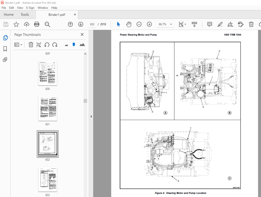
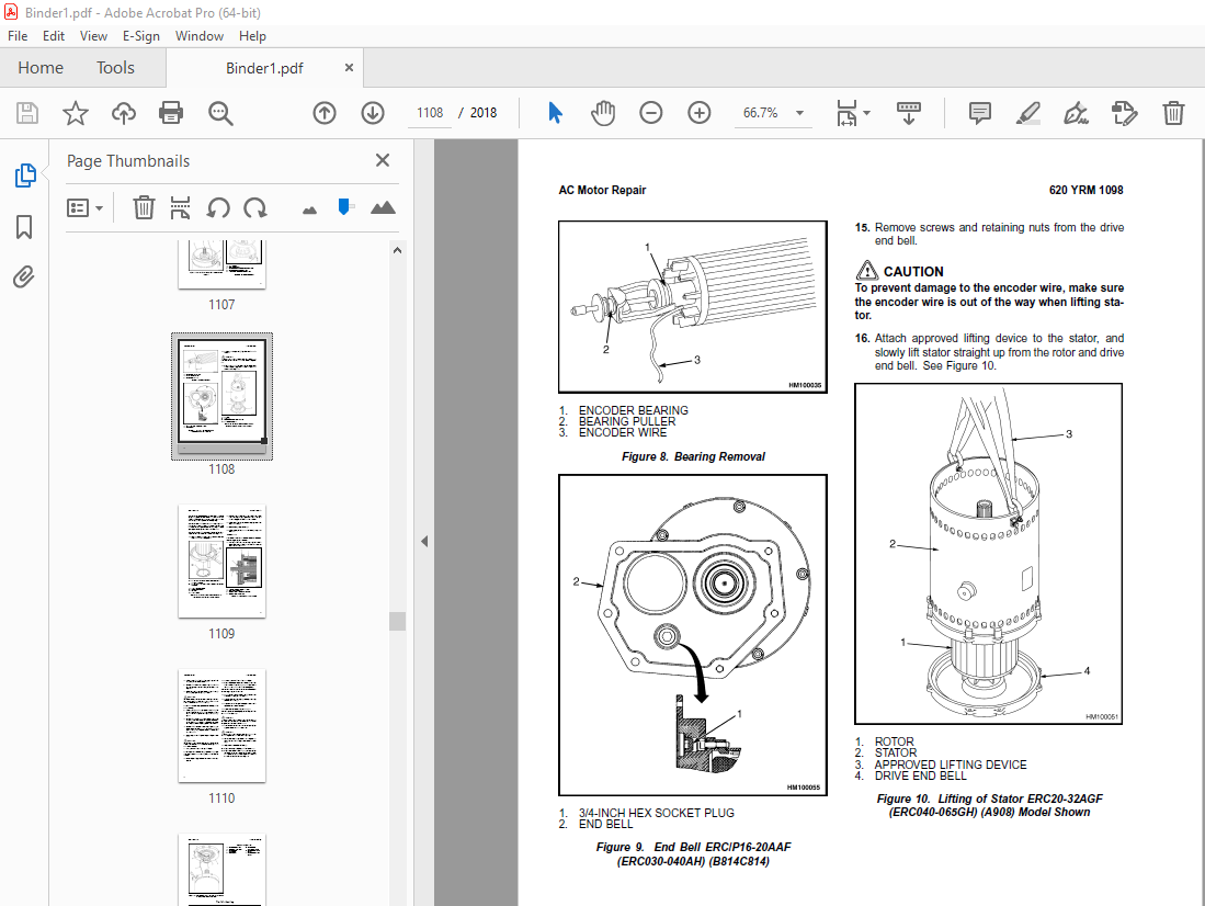
TABLE OF CONTENTS:
Yale Forklift C839 (ERC35HG, ERC40HG, ERC45HG, ERC55HG) Service Manual – PDF DOWNLOAD
524150783-1600YRM0326-(03-2007)-UK-EN (2) 1
toc 1
Steering Axle 1
Safety Precautions Maintenance and Repair 2
General 5
Description 5
Steering Axle Assembly Repair 10
Steering Axle GP/GLP/GDP070-110LG/MG (B813), GC/GLC070-120LG/MG 10
Remove 10
Install 10
Steering Axle GDP60-70CA (GP/GLP/GDP135-155CA) (A878, B878), GLP 11
Remove 11
Install 11
Wheels and Hubs Repair (All Units) 12
Remove and Disassemble 12
Clean 12
Inspect 12
Assemble and Install 12
Spindles and Bearings Repair (All Units) 14
Remove 14
Clean 14
Assemble and Install 15
Tie Rods Repair (All Units) 16
Remove 16
Clean 16
Install 16
Steering Cylinder Repair 19
Remove and Disassemble 19
Clean and Inspect 19
Assemble and Install 19
Troubleshooting 20
524150783-1600YRM0326-(03-2007)-UK-EN 25
toc 25
Steering Axle 25
Safety Precautions Maintenance and Repair 26
General 29
Description 29
Steering Axle Assembly Repair 34
Steering Axle GP/GLP/GDP070-110LG/MG (B813), GC/GLC070-120LG/MG 34
Remove 34
Install 34
Steering Axle GDP60-70CA (GP/GLP/GDP135-155CA) (A878, B878), GLP 35
Remove 35
Install 35
Wheels and Hubs Repair (All Units) 36
Remove and Disassemble 36
Clean 36
Inspect 36
Assemble and Install 36
Spindles and Bearings Repair (All Units) 38
Remove 38
Clean 38
Assemble and Install 39
Tie Rods Repair (All Units) 40
Remove 40
Clean 40
Install 40
Steering Cylinder Repair 43
Remove and Disassemble 43
Clean and Inspect 43
Assemble and Install 43
Troubleshooting 44
524150797-8000YRM0231-(02-2023)-UK-EN 49
General 55
Threaded Fasteners 55
Nomenclature, Threads 55
Strength Identification 56
Cotter (Split) Pins 57
Fastener Torque Tables 62
Conversion Table 64
524150797-8000YRM0231-(03-2020)-UK-EN 71
General 75
Threaded Fasteners 75
Nomenclature, Threads 75
Strength Identification 76
Cotter (Split) Pins 77
Fastener Torque Tables 82
Conversion Table 84
524153920-4000YRM0736-(07-2010)-UK-EN (2) 91
toc 91
Masts 91
Safety Precautions Maintenance and Repair 92
General 95
Description and Operation 95
Carriages 95
Two-Stage Mast With Limited Free-Lift 95
Two-Stage Mast With Full Free-Lift 96
Three-Stage Mast With Full Free-Lift 97
Safety Procedures When Working Near Mast 99
Fork Replacement 101
Remove 102
Install 102
Carriage Repair 103
Remove 103
Sideshift Carriage Repair 105
Remove 105
Disassemble 105
Assemble 105
Install 105
Two-Stage Mast With Limited Free-Lift Repair 107
Remove, GLP/GDP3 5-5 5LJ/MJ (GP/GLP/GDP070-120LJ/MJ) Model Lift 107
Remove, GC070-120LJ/MJ, ERC070-120HG (A839), and ERC35-55HG (ERC 109
Disassemble 112
Clean and Inspect 112
Assemble 113
Install, GLP/GDP3 5-5 5LJ/MJ (GP/GLP/GDP070-120LJ/MJ) Lift Truck 114
Install, GC070-120LJ/MJ, ERC070-120HG (A839), and ERC35-55HG (ER 116
Two-Stage Mast With Full Free-Lift Repair 118
Remove 118
Disassemble 118
Clean and Inspect 120
Assemble 120
Install 120
Three-Stage Mast With Full Free-Lift Repair 122
Remove 122
Disassemble 122
Clean and Inspect 126
Assemble 126
Install 127
Mast Operation Check 133
Lift and Tilt System Leak Check 134
Lift System 134
Tilt System 135
Tilt Cylinder Stroke and Backward Tilt Angle Adjustment 136
Lift Chain Adjustments 138
Mast Adjustments 140
Carriage Adjustment 142
Troubleshooting 143
tables 91
Table 1 Tilt Cylinder Leak Check Specifications, GC070-120LJ/MJ 135
Table 2 Hook-Type Carriage Chain Adjustment 138
Table 3 Pin-Type Carriage Chain Adjustment 139
524153920-4000YRM0736-(07-2010)-UK-EN 149
toc 149
Masts 149
Safety Precautions Maintenance and Repair 150
General 153
Description and Operation 153
Carriages 153
Two-Stage Mast With Limited Free-Lift 153
Two-Stage Mast With Full Free-Lift 154
Three-Stage Mast With Full Free-Lift 155
Safety Procedures When Working Near Mast 157
Fork Replacement 159
Remove 160
Install 160
Carriage Repair 161
Remove 161
Sideshift Carriage Repair 163
Remove 163
Disassemble 163
Assemble 163
Install 163
Two-Stage Mast With Limited Free-Lift Repair 165
Remove, GLP/GDP3 5-5 5LJ/MJ (GP/GLP/GDP070-120LJ/MJ) Model Lift 165
Remove, GC070-120LJ/MJ, ERC070-120HG (A839), and ERC35-55HG (ERC 167
Disassemble 170
Clean and Inspect 170
Assemble 171
Install, GLP/GDP3 5-5 5LJ/MJ (GP/GLP/GDP070-120LJ/MJ) Lift Truck 172
Install, GC070-120LJ/MJ, ERC070-120HG (A839), and ERC35-55HG (ER 174
Two-Stage Mast With Full Free-Lift Repair 176
Remove 176
Disassemble 176
Clean and Inspect 178
Assemble 178
Install 178
Three-Stage Mast With Full Free-Lift Repair 180
Remove 180
Disassemble 180
Clean and Inspect 184
Assemble 184
Install 185
Mast Operation Check 191
Lift and Tilt System Leak Check 192
Lift System 192
Tilt System 193
Tilt Cylinder Stroke and Backward Tilt Angle Adjustment 194
Lift Chain Adjustments 196
Mast Adjustments 198
Carriage Adjustment 200
Troubleshooting 201
tables 149
Table 1 Tilt Cylinder Leak Check Specifications, GC070-120LJ/MJ 193
Table 2 Hook-Type Carriage Chain Adjustment 196
Table 3 Pin-Type Carriage Chain Adjustment 197
524158040-2240YRM0001-(01-2023)-UK-EN 207
General 213
Battery Type 213
Lead-Acid Batteries 213
Lithium-Ion Batteries 214
Specific Gravity 214
Chemical Reaction in a Cell 214
Electrical Terms 216
Battery Selection 217
Battery Voltage 218
Battery as a Counterweight 218
Battery Ratings 218
Kilowatt-Hours 218
Battery Maintenance 219
Safety Procedures 219
Maintenance Records 219
New Battery 219
Cleaning Battery 220
Adding Water to Battery 222
Hydrometer 222
Battery Temperature 223
Charging Battery 224
Types of Battery Charges 225
Methods of Charging 226
Troubleshooting Charger 227
Knowing When Battery Is Fully Charged 227
Where to Charge Batteries 227
Equipment Needed 227
Battery Connectors 228
Battery Care 228
Troubleshooting 230
524158040-2240YRM0001-(03-2020)-UK-EN 235
General 239
Battery Type 239
Lead-Acid Batteries 239
Lithium-Ion Batteries 240
Specific Gravity 240
Chemical Reaction in a Cell 240
Electrical Terms 242
Battery Selection 242
Battery Voltage 243
Battery as a Counterweight 244
Battery Ratings 244
Kilowatt-Hours 244
Battery Maintenance 244
Safety Procedures 244
Maintenance Records 245
New Battery 245
Cleaning Battery 245
Adding Water to Battery 247
Hydrometer 248
Battery Temperature 249
Charging Battery 250
Types of Battery Charges 250
Methods of Charging 252
Troubleshooting Charger 252
Knowing When Battery Is Fully Charged 253
Where to Charge Batteries 253
Equipment Needed 253
Battery Connectors 254
Battery Care 254
Troubleshooting 256
524158753-1600YRM0720-(11-2006)-UK-EN 261
toc 261
Steering Housing and Control Unit 261
Safety Precautions Maintenance and Repair 262
General 265
Description 265
Operation 266
Steering Wheel and Column Assembly Repair 267
Assembly Components, Remove 267
Steering Control Unit, Disassemble 272
Steering Control Unit, Clean 272
Steering Control Unit, Assemble 272
Assembly Components, Install 274
System Air Removal 276
Troubleshooting 276
524158753-1600YRM0720-(11-2006)-UK-EN_2 281
toc 281
Steering Housing and Control Unit 281
Safety Precautions Maintenance and Repair 282
General 285
Description 285
Operation 286
Steering Wheel and Column Assembly Repair 287
Assembly Components, Remove 287
Steering Control Unit, Disassemble 292
Steering Control Unit, Clean 292
Steering Control Unit, Assemble 292
Assembly Components, Install 294
System Air Removal 296
Troubleshooting 296
524166834-1400YRM0413-(11-2006)-UK-EN (2) 301
toc 301
Drive Axle, Speed Reducer, and Differential 301
Safety Precautions Maintenance and Repair 302
General 305
Description 305
Drive Axle, Speed Reducer, and Differential Repair 306
Remove 306
General 306
Traction Motor, Speed Reducer, and Differential 307
Motor, Speed Reducer, and Differential, Remove 307
Disassemble 310
Speed Reducer 310
Differential 311
Clean 312
Inspect 312
Assemble 312
Speed Reducer 312
Input Gear, Install 312
New Pinion, Install 312
Differential 315
Drive Axle Housing 318
Remove 318
Clean 319
Inspect 319
Assemble 319
Troubleshooting 322
tables 301
Table 1 Pinion Assembly Shims Adjustment 314
Table 2 Ring and Pinion Tooth Contact Adjustment 316
524166834-1400YRM0413-(11-2006)-UK-EN 325
toc 325
Drive Axle, Speed Reducer, and Differential 325
Safety Precautions Maintenance and Repair 326
General 329
Description 329
Drive Axle, Speed Reducer, and Differential Repair 330
Remove 330
General 330
Traction Motor, Speed Reducer, and Differential 331
Motor, Speed Reducer, and Differential, Remove 331
Disassemble 334
Speed Reducer 334
Differential 335
Clean 336
Inspect 336
Assemble 336
Speed Reducer 336
Input Gear, Install 336
New Pinion, Install 336
Differential 339
Drive Axle Housing 342
Remove 342
Clean 343
Inspect 343
Assemble 343
Troubleshooting 346
tables 325
Table 1 Pinion Assembly Shims Adjustment 338
Table 2 Ring and Pinion Tooth Contact Adjustment 340
524166837-1800YRM0338-(05-2009)-UK-EN (2) 349
toc 349
Brake System 349
Safety Precautions Maintenance and Repair 350
General 353
Description and Operation 353
Brake Booster and Master Cylinder 353
Master Cylinder 353
Service Brake Assembly 353
Parking Brake 357
Seat Brake 358
Brake Shoe Assemblies Repair 359
Remove and Disassemble 359
Clean and Inspect 359
Assemble and Install 361
Master Cylinder Repair 365
Master Cylinder For Lift Truck Models GC/GLC70-120LG/MG (B818) a 365
Remove 365
Disassemble 365
Assemble 366
Install 366
Master Cylinder For Lift Truck Models ERC70-120HD, ERC70-120HG ( 367
Remove and Disassemble 367
Clean and Inspect 368
Assemble and Install 368
Brake Booster Repair 368
Remove 368
Disassemble 368
Clean and Inspect 369
Assemble 370
Install 370
Brake System Air Removal 370
Brake Pedal Adjustment 370
Brake Pedal GP/GLP/GDP70-120LG/MG (B813) With Manual Transmissio 370
Brake Shoes Adjustment 372
Parking Brake Adjustment 372
Parking Brake Adjustment, Lift Truck Models GC/GLC70-120LG/MG (B 372
Parking Brake Lever and Switch Adjustment ERC70-120HD and ERC70- 373
Seat Brake Assembly 374
Remove 374
Clean and Inspect 374
Install 374
Adjustments 376
Solenoid Adjustment 376
Traction cutoff Switch Adjustment 376
Cable Adjustment 376
Brake Booster Relief Valve Check 379
Troubleshooting 379
524166837-1800YRM0338-(05-2009)-UK-EN 385
toc 385
Brake System 385
Safety Precautions Maintenance and Repair 386
General 389
Description and Operation 389
Brake Booster and Master Cylinder 389
Master Cylinder 389
Service Brake Assembly 389
Parking Brake 393
Seat Brake 394
Brake Shoe Assemblies Repair 395
Remove and Disassemble 395
Clean and Inspect 395
Assemble and Install 397
Master Cylinder Repair 401
Master Cylinder For Lift Truck Models GC/GLC70-120LG/MG (B818) a 401
Remove 401
Disassemble 401
Assemble 402
Install 402
Master Cylinder For Lift Truck Models ERC70-120HD, ERC70-120HG ( 403
Remove and Disassemble 403
Clean and Inspect 404
Assemble and Install 404
Brake Booster Repair 404
Remove 404
Disassemble 404
Clean and Inspect 405
Assemble 406
Install 406
Brake System Air Removal 406
Brake Pedal Adjustment 406
Brake Pedal GP/GLP/GDP70-120LG/MG (B813) With Manual Transmissio 406
Brake Shoes Adjustment 408
Parking Brake Adjustment 408
Parking Brake Adjustment, Lift Truck Models GC/GLC70-120LG/MG (B 408
Parking Brake Lever and Switch Adjustment ERC70-120HD and ERC70- 409
Seat Brake Assembly 410
Remove 410
Clean and Inspect 410
Install 410
Adjustments 412
Solenoid Adjustment 412
Traction cutoff Switch Adjustment 412
Cable Adjustment 412
Brake Booster Relief Valve Check 415
Troubleshooting 415
524166839-2000YRM0077-(02-2009)-UK-EN (2) 421
toc 421
Manual hydraulic Control Valve 421
Safety Precautions Maintenance and Repair 422
General 425
Description 425
Operation 427
Lift Section 429
Tilt Section 430
Tilt Backward 430
Tilt Forward 430
Relief Valve 432
Solenoid Valve for Auxiliary Function 433
Main Control Valve Repair 434
Remove and Disassemble – Control Valve Without OPS Solenoid 434
Remove and Disassemble – Control Valve With OPS Solenoid 434
Clean and Inspect 436
Assemble – Control Valve Without OPS 436
Assemble – Control Valve With OPS 436
Install 437
Solenoid Valve for Auxiliary Function Repair 437
Remove and Disassemble 437
Assemble and Install 439
Troubleshooting 439
Pressure Relief Valve Check and Adjustment 440
Primary Relief Valve 440
Secondary Relief Valve 440
Control Lever Arrangement and Adjustment 441
Specifications 443
Troubleshooting 443
524166839-2000YRM0077-(02-2009)-UK-EN 449
toc 449
Manual hydraulic Control Valve 449
Safety Precautions Maintenance and Repair 450
General 453
Description 453
Operation 455
Lift Section 457
Tilt Section 458
Tilt Backward 458
Tilt Forward 458
Relief Valve 460
Solenoid Valve for Auxiliary Function 461
Main Control Valve Repair 462
Remove and Disassemble – Control Valve Without OPS Solenoid 462
Remove and Disassemble – Control Valve With OPS Solenoid 462
Clean and Inspect 464
Assemble – Control Valve Without OPS 464
Assemble – Control Valve With OPS 464
Install 465
Solenoid Valve for Auxiliary Function Repair 465
Remove and Disassemble 465
Assemble and Install 467
Troubleshooting 467
Pressure Relief Valve Check and Adjustment 468
Primary Relief Valve 468
Secondary Relief Valve 468
Control Lever Arrangement and Adjustment 469
Specifications 471
Troubleshooting 471
524179945-1900YRM0559-(04-2009)-UK-EN (2) 477
toc 477
Hydraulic System 477
Safety Precautions Maintenance and Repair 478
General 481
Description 481
Hydraulic System 481
Operation 489
Hydraulic System 489
Hydraulic Gear Pump 495
Steering Pump 495
Hydraulic Tank Repair 503
Tank, Remove [ERC/P16-20AAF (ERC030-040AF, AG/BG) (A814); ERC/P1 503
Tank, Remove [ERP20-30ALF (B216) and ERP20-30ALF (ERP040-060DH) 505
Tank, Remove [ERP20-32ALF (ERP040-065DH) (E216)] 506
Hydraulic Tank [ERC35-55HG (ERC70-120HH) (B839/C839)] 506
Inspect 507
Small Leaks, Repair 508
Large Leaks, Repair 508
Clean 508
Steam Method 508
Chemical Solution Method 509
Additional Methods for Tank Repair 509
Tank, Install [ERC/P16-20AAF (ERC030-040AF, AG/BG) (A814); ERC/P 509
Tank, Install [ERP20-30ALF (B216) and ERP20-30ALF (ERP040-060DH) 510
Tank, Install [ERP20-32ALF (ERP040-065DH) (E216)] 510
Filter Replacement 511
All Lift Trucks Except [ERC35-55HG (ERC70-120HH) (B839/C839); ER 511
Remove 511
Install 512
Lift Truck Models [ERC35-55HG (ERC70-120HH) (B839/C839)] 512
Remove 512
Install 512
Lift truck Models [ERC20-32AGF (ERC040-065GH) (A908) and ERC/P16 513
Remove 513
Install 513
Lift Truck Models [ERP20-32ALF (ERP040-065DH) (E216)] 515
Remove 515
Install 515
Hydraulic Pump Repair 518
Hydraulic Pump, Remove [ERC/P16-20AAF (ERC030-040AF, AG/BG) (A81 518
Hydraulic Pump, Disassemble ERC/P16-20AAF (ERC030-040AF, AG/BG) 518
Inspect 520
Clean 520
Pump Seal Replace and Pump Assemble 520
Assemble Pump on Motor 520
Hydraulic Pump and Motor, Install [ERC/P16-20AAF (ERC030-040AF, 522
Hydraulic Pump, Remove [ERP20-30ALF (B216); ERP20-30ALF (ERP040- 523
Hydraulic Pump, Disassemble [ERC35-55HG (ERC70-120HH) (B839/C839 524
Hydraulic Pump, Inspect [ERC35-55HG (ERC70-120HH) (B839/C839) an 526
Hydraulic Pump, Clean [ERC35-55HG (ERC70-120HH) (B839/C839) and 526
Hydraulic Pump, Assemble [ERC35-55HG (ERC70-120HH) (B839/C839) a 526
Hydraulic Pump and Motor, Install [ERP20-30ALF (B216); ERP20-30A 526
Main Control Valve Repair 528
Steering Pump Repair 528
Pump, Remove and Disassemble [ERC/P16-20AAF (ERC030-040AF, ERC03 528
Pump, Remove and Disassemble [ERP20-30ALF (B216); ERP20-30ALF (E 530
Pump, Assemble and Install 532
Steering Control Unit Replacement 533
Remove 533
Install 533
Steering Cylinder Repair 539
Main Control Valve Check and Adjust 539
Steering Relief Valve Check and Adjust 540
Specifications 540
Relief Valve Pressures* 540
Hydraulic Tank Capacity (dipstick full mark) 541
Hydraulic Pump Capacities – All Models Except ERC35-55HG (ERC70- 541
Hydraulic Pump Capacities – Models ERC35-55HG (ERC70-120HH) (B83 541
Troubleshooting 541
Steering 541
Steering Housing and Steering Control Unit 542
Hydraulic System 543
524179945-1900YRM0559-(04-2009)-UK-EN 549
toc 549
Hydraulic System 549
Safety Precautions Maintenance and Repair 550
General 553
Description 553
Hydraulic System 553
Operation 561
Hydraulic System 561
Hydraulic Gear Pump 567
Steering Pump 567
Hydraulic Tank Repair 575
Tank, Remove [ERC/P16-20AAF (ERC030-040AF, AG/BG) (A814); ERC/P1 575
Tank, Remove [ERP20-30ALF (B216) and ERP20-30ALF (ERP040-060DH) 577
Tank, Remove [ERP20-32ALF (ERP040-065DH) (E216)] 578
Hydraulic Tank [ERC35-55HG (ERC70-120HH) (B839/C839)] 578
Inspect 579
Small Leaks, Repair 580
Large Leaks, Repair 580
Clean 580
Steam Method 580
Chemical Solution Method 581
Additional Methods for Tank Repair 581
Tank, Install [ERC/P16-20AAF (ERC030-040AF, AG/BG) (A814); ERC/P 581
Tank, Install [ERP20-30ALF (B216) and ERP20-30ALF (ERP040-060DH) 582
Tank, Install [ERP20-32ALF (ERP040-065DH) (E216)] 582
Filter Replacement 583
All Lift Trucks Except [ERC35-55HG (ERC70-120HH) (B839/C839); ER 583
Remove 583
Install 584
Lift Truck Models [ERC35-55HG (ERC70-120HH) (B839/C839)] 584
Remove 584
Install 584
Lift truck Models [ERC20-32AGF (ERC040-065GH) (A908) and ERC/P16 585
Remove 585
Install 585
Lift Truck Models [ERP20-32ALF (ERP040-065DH) (E216)] 587
Remove 587
Install 587
Hydraulic Pump Repair 590
Hydraulic Pump, Remove [ERC/P16-20AAF (ERC030-040AF, AG/BG) (A81 590
Hydraulic Pump, Disassemble ERC/P16-20AAF (ERC030-040AF, AG/BG) 590
Inspect 592
Clean 592
Pump Seal Replace and Pump Assemble 592
Assemble Pump on Motor 592
Hydraulic Pump and Motor, Install [ERC/P16-20AAF (ERC030-040AF, 594
Hydraulic Pump, Remove [ERP20-30ALF (B216); ERP20-30ALF (ERP040- 595
Hydraulic Pump, Disassemble [ERC35-55HG (ERC70-120HH) (B839/C839 596
Hydraulic Pump, Inspect [ERC35-55HG (ERC70-120HH) (B839/C839) an 598
Hydraulic Pump, Clean [ERC35-55HG (ERC70-120HH) (B839/C839) and 598
Hydraulic Pump, Assemble [ERC35-55HG (ERC70-120HH) (B839/C839) a 598
Hydraulic Pump and Motor, Install [ERP20-30ALF (B216); ERP20-30A 598
Main Control Valve Repair 600
Steering Pump Repair 600
Pump, Remove and Disassemble [ERC/P16-20AAF (ERC030-040AF, ERC03 600
Pump, Remove and Disassemble [ERP20-30ALF (B216); ERP20-30ALF (E 602
Pump, Assemble and Install 604
Steering Control Unit Replacement 605
Remove 605
Install 605
Steering Cylinder Repair 611
Main Control Valve Check and Adjust 611
Steering Relief Valve Check and Adjust 612
Specifications 612
Relief Valve Pressures* 612
Hydraulic Tank Capacity (dipstick full mark) 613
Hydraulic Pump Capacities – All Models Except ERC35-55HG (ERC70- 613
Hydraulic Pump Capacities – Models ERC35-55HG (ERC70-120HH) (B83 613
Troubleshooting 613
Steering 613
Steering Housing and Steering Control Unit 614
Hydraulic System 615
524183081-1600YRM1054-(11-2006)-UK-EN (2) 621
toc 621
Steering System for AC Electric Lift Trucks 621
Safety Precautions Maintenance and Repair 622
General 625
Description 626
Steering Wheel and Column Assembly Repair 627
General 627
Assembly Components, Remove 629
Assembly Components, Install 630
Power Steering Motor and Pump 631
Description 631
Remove 631
Disassemble 634
Install 634
Power Steering Pump, Repair 634
Seal, Replace 635
Steering System Air Removal 636
Steering Pressure Check 636
Steering Motor Circuits Check 637
Troubleshooting 638
524183081-1600YRM1054-(11-2006)-UK-EN 643
toc 643
Steering System for AC Electric Lift Trucks 643
Safety Precautions Maintenance and Repair 644
General 647
Description 648
Steering Wheel and Column Assembly Repair 649
General 649
Assembly Components, Remove 651
Assembly Components, Install 652
Power Steering Motor and Pump 653
Description 653
Remove 653
Disassemble 656
Install 656
Power Steering Pump, Repair 656
Seal, Replace 657
Steering System Air Removal 658
Steering Pressure Check 658
Steering Motor Circuits Check 659
Troubleshooting 660
524183082-2200YRM1055-(10-2009)-UK-EN (2) 665
toc 665
Electrical System (Trucks With AC Controllers) 665
Safety Precautions Maintenance and Repair 666
General 669
Description 670
Features of the Display Panels 670
Other Control Components 671
Display Panel and Key Switch Replacement 672
Display Panel, Replace 672
Key Switch, Replace 674
Controller Replacement 674
Traction and Pump Motor Controller Replacement 674
Master Controller, Replace 680
Master Controller, Remove ERP20-30ALF (ERP040-060DH) (D216), ERP 680
Master Controller, Install ERP20-30ALF (ERP040-060DH) (D216), ER 680
Master Controller, Remove ERC/P16-20AAF (ERC030-040AH) (B814/C81 682
Master Controller, Install ERC/P16-20AAF (ERC030-040AH) (B814/C8 682
Master Controller, Remove ERC35-55HG (ERC070-120HH) (B839/C839) 684
Master Controller, Install ERC35-55HG (ERC070-120HH) (B839/C839) 684
Control Components Replacement 685
General 685
Start Switch, Replace 685
Brake Light Switch, Replace 686
Seat Switch, Replace 686
Parking Brake Switch, Replace 687
Foot Directional Control Pedal Direction Switches, Replace 689
Steering Column Direction Control Switches, Replace 692
Remove 692
Install 692
Brake Fluid Switch, Replace 694
Brush Wear and Over Temperature Sensors (DC Pump Motor Only) 694
Rocker Switches for Lights, Replace 694
Accelerator Position Sensor, Replace 695
On-Demand Steering Sensor, Replace 696
Lights, Converter, Relay, and Reverse Alarm 696
Brake, Tail, and Reverse Light Assembly, Replace 697
Incandescent Assembly 697
LED Assembly – Remove 699
LED Assembly – Install 699
Strobe Light Assembly, Replace 702
Wire Harness Repair 703
Del-City Crimp-Solder-Shrink Splice 703
Front, Rear Driving Light or Spot Light Assemblies, Replace 704
Converter, Replace 704
Remove, Lift Truck Models ERP20-30ALF (ERP040-060DH) (D216), ERP 704
Install, Lift Truck Models ERP20-30ALF (ERP040-060DH) (D216), ER 706
Remove, Lift Truck Models ERC20-32AGF (ERC040-065GH) (A908) and 706
Install, Lift Truck Models ERC20-32AGF (ERC040-065GH) (A908) and 706
Remove, Lift Truck Models ERC35-55HG (ERC70-120HH) (B839/C839) 708
Install, Lift Truck Models ERC35-55HG (ERC70-120HH) (B839/C839) 708
Reverse Relay, Replace 709
Lift Truck Models ERC20-32AGF (ERC040-065GH) (A908), ERC/P16-20A 709
Lift Truck Models ERC35-55HG (ERC70-120HH) (B839/C839) 709
Backup Alarm, Replace 711
Horn and Horn Button, Replace 711
Horn Replacement for Lift Trucks ERP20-30ALF (ERP040-060DH) (D21 711
Horn Replacement for Lift Trucks ERC35-55HG (ERC70-120HH) (B839/ 713
Horn Switch and Cover, Replace 714
Hydraulic Pump Switches 715
Fan Power Supply, Replace 715
Remove, Lift Truck Models ERC35-55HG (ERC70-120HH) (B839/C839) 715
Install, Lift Truck Models ERC35-55HG (ERC70-120HH) (B839/C839) 715
Remove, Lift Truck Models ERP20-30ALF (ERP040-060DH) (D216) and 716
Install, Lift Truck Models ERP20-30ALF (ERP040-060DH) (D216) and 717
Remove, Lift Truck Models ERC20-32AGF (ERC040-065GH) (A908) 717
Install, Lift Truck Models ERC20-32AGF (ERC040-065GH) (A908) 717
Control and Power Fuse Check 718
Fuse Locations 718
Brake Light Switch Adjustment 724
Seat Switch Check 725
Seat Brake Adjustment 725
Parking Brake Switch Adjustment 726
Direction Switches Check 726
Foot Directional Control Pedal 726
Steering Column 727
Foot Directional Control Pedal or Accelerator Pedal Adjustment 727
Accelerator Position Sensor Adjustment and Start Switch Adjustme 728
Acceleration Position Sensor, Adjust 728
Start Switch, Adjust 730
tables 665
Table 1 Wire Splice Size 703
524183082-2200YRM1055-(10-2009)-UK-EN 733
toc 733
Electrical System (Trucks With AC Controllers) 733
Safety Precautions Maintenance and Repair 734
General 737
Description 738
Features of the Display Panels 738
Other Control Components 739
Display Panel and Key Switch Replacement 740
Display Panel, Replace 740
Key Switch, Replace 742
Controller Replacement 742
Traction and Pump Motor Controller Replacement 742
Master Controller, Replace 748
Master Controller, Remove ERP20-30ALF (ERP040-060DH) (D216), ERP 748
Master Controller, Install ERP20-30ALF (ERP040-060DH) (D216), ER 748
Master Controller, Remove ERC/P16-20AAF (ERC030-040AH) (B814/C81 750
Master Controller, Install ERC/P16-20AAF (ERC030-040AH) (B814/C8 750
Master Controller, Remove ERC35-55HG (ERC070-120HH) (B839/C839) 752
Master Controller, Install ERC35-55HG (ERC070-120HH) (B839/C839) 752
Control Components Replacement 753
General 753
Start Switch, Replace 753
Brake Light Switch, Replace 754
Seat Switch, Replace 754
Parking Brake Switch, Replace 755
Foot Directional Control Pedal Direction Switches, Replace 757
Steering Column Direction Control Switches, Replace 760
Remove 760
Install 760
Brake Fluid Switch, Replace 762
Brush Wear and Over Temperature Sensors (DC Pump Motor Only) 762
Rocker Switches for Lights, Replace 762
Accelerator Position Sensor, Replace 763
On-Demand Steering Sensor, Replace 764
Lights, Converter, Relay, and Reverse Alarm 764
Brake, Tail, and Reverse Light Assembly, Replace 765
Incandescent Assembly 765
LED Assembly – Remove 767
LED Assembly – Install 767
Strobe Light Assembly, Replace 770
Wire Harness Repair 771
Del-City Crimp-Solder-Shrink Splice 771
Front, Rear Driving Light or Spot Light Assemblies, Replace 772
Converter, Replace 772
Remove, Lift Truck Models ERP20-30ALF (ERP040-060DH) (D216), ERP 772
Install, Lift Truck Models ERP20-30ALF (ERP040-060DH) (D216), ER 774
Remove, Lift Truck Models ERC20-32AGF (ERC040-065GH) (A908) and 774
Install, Lift Truck Models ERC20-32AGF (ERC040-065GH) (A908) and 774
Remove, Lift Truck Models ERC35-55HG (ERC70-120HH) (B839/C839) 776
Install, Lift Truck Models ERC35-55HG (ERC70-120HH) (B839/C839) 776
Reverse Relay, Replace 777
Lift Truck Models ERC20-32AGF (ERC040-065GH) (A908), ERC/P16-20A 777
Lift Truck Models ERC35-55HG (ERC70-120HH) (B839/C839) 777
Backup Alarm, Replace 779
Horn and Horn Button, Replace 779
Horn Replacement for Lift Trucks ERP20-30ALF (ERP040-060DH) (D21 779
Horn Replacement for Lift Trucks ERC35-55HG (ERC70-120HH) (B839/ 781
Horn Switch and Cover, Replace 782
Hydraulic Pump Switches 783
Fan Power Supply, Replace 783
Remove, Lift Truck Models ERC35-55HG (ERC70-120HH) (B839/C839) 783
Install, Lift Truck Models ERC35-55HG (ERC70-120HH) (B839/C839) 783
Remove, Lift Truck Models ERP20-30ALF (ERP040-060DH) (D216) and 784
Install, Lift Truck Models ERP20-30ALF (ERP040-060DH) (D216) and 785
Remove, Lift Truck Models ERC20-32AGF (ERC040-065GH) (A908) 785
Install, Lift Truck Models ERC20-32AGF (ERC040-065GH) (A908) 785
Control and Power Fuse Check 786
Fuse Locations 786
Brake Light Switch Adjustment 792
Seat Switch Check 793
Seat Brake Adjustment 793
Parking Brake Switch Adjustment 794
Direction Switches Check 794
Foot Directional Control Pedal 794
Steering Column 795
Foot Directional Control Pedal or Accelerator Pedal Adjustment 795
Accelerator Position Sensor Adjustment and Start Switch Adjustme 796
Acceleration Position Sensor, Adjust 796
Start Switch, Adjust 798
tables 733
Table 1 Wire Splice Size 771
524183083-2200YRM1056-(03-2009)-UK-EN (2) 801
toc 801
AC Motor Controllers/Display Panel 801
Safety Precautions Maintenance and Repair 802
Description 805
General 805
AC Motors 805
Motor Controllers 805
Master Controller 805
Dash Display 805
Controller Area Network Bus (CANbus) 805
Master Controller Checks and Adjustments 806
Function Settings 807
General 807
Function Numbers 807
Function Descriptions 810
General 810
Function Number 1 BATTERY VOLTAGE 810
Function Number 2 EXTENDED SHIFT 810
Function Number 3 ACCELERATION 1 810
Function Number 4 ACCELERATION 2 810
Function Number 5 TOP SPEED LIMIT 810
Function Number 6 REGEN BRAKING 810
Function Number 7 AUTO DECELERATION 811
Function Number 8 BDI ADJUSTMENT 811
Function Number 9 LIFT INTERRUPT 811
Function Number 10 POWER STEERING TIME DELAY 811
Function Number 11 SERVICE REMINDER 811
Function Number 12 CUSTOM 811
Function Number 13 PUMP SPEED 1 811
Function Number 14 PUMP SPEED 2 812
Function Number 15 PUMP SPEED 3 812
Function Number 16 PUMP ACCELERATION 812
Troubleshooting 812
General 812
Controller Status Light Emitting Diodes (LEDs) 813
Master Controller 813
AC Motor Controllers 813
Status Codes 819
AC Motor Controllers Status Code Charts 821
Troubleshooting When Dash and/or Lift Truck is not Operational 842
Typical Symptoms 842
Truck Runs but Dash Display is not Operational, or Only Displays 842
Truck Does Not Run and Dash is Not Operational or Only Displays 843
Hydraulics Operate Normally, Traction Does Not Operate Correctly 844
Traction Operates Normally, Hydraulics do Not Operate Correctly, 844
AC Transistor Motor Controller Replacement 844
General 844
General Maintenance Instructions 850
Special Precautions 850
Fuses 851
Fan Test 851
Contactors 851
Repair 851
Thermal Sensors 855
Motor Controller, Replace 855
Display Panel 856
General 856
Premium Display Panel 856
Standard Display Panel 856
Display Functions and Features 857
Key-On Initialization 857
Standard Display 858
Premium Display 858
Lift Truck Inspection Function 859
Access to Service Functions 859
Service Functions 859
Service Functions 860
Performance Modes 862
Battery Discharge Indicator (BDI) 862
Hourmeter 863
Dash Display Service Menu Navigation 869
General 869
Moving Through Menu Selections 869
Editing and Adding Information 869
tables 801
Table 1 Factory Parameters for ERP20-30ALF (ERP040-060DH) (D216 807
Table 2 Factory Setting for ERC020-032AGF (ERC40-65GH) (A908) 808
Table 3 Factory Setting for ERC/P16-20AAF (ERC030-040AH) (B814/ 808
Table 4 Factory Parameters for ERC35-55HG (ERC70-120HH) (B839/C 809
Table 5 List of Status Codes 819
Table 6 42-Pin Connections/Descriptions for Master Controller 852
Table 7 Pin Connections/Descriptions for 72/80 (Gen IV) Volt Mo 854
Table 8 Pin Connections/Descriptions for 36/48 and 72v/80v (Gen 854
524183083-2200YRM1056-(03-2009)-UK-EN 873
toc 873
AC Motor Controllers/Display Panel 873
Safety Precautions Maintenance and Repair 874
Description 877
General 877
AC Motors 877
Motor Controllers 877
Master Controller 877
Dash Display 877
Controller Area Network Bus (CANbus) 877
Master Controller Checks and Adjustments 878
Function Settings 879
General 879
Function Numbers 879
Function Descriptions 882
General 882
Function Number 1 BATTERY VOLTAGE 882
Function Number 2 EXTENDED SHIFT 882
Function Number 3 ACCELERATION 1 882
Function Number 4 ACCELERATION 2 882
Function Number 5 TOP SPEED LIMIT 882
Function Number 6 REGEN BRAKING 882
Function Number 7 AUTO DECELERATION 883
Function Number 8 BDI ADJUSTMENT 883
Function Number 9 LIFT INTERRUPT 883
Function Number 10 POWER STEERING TIME DELAY 883
Function Number 11 SERVICE REMINDER 883
Function Number 12 CUSTOM 883
Function Number 13 PUMP SPEED 1 883
Function Number 14 PUMP SPEED 2 884
Function Number 15 PUMP SPEED 3 884
Function Number 16 PUMP ACCELERATION 884
Troubleshooting 884
General 884
Controller Status Light Emitting Diodes (LEDs) 885
Master Controller 885
AC Motor Controllers 885
Status Codes 891
AC Motor Controllers Status Code Charts 893
Troubleshooting When Dash and/or Lift Truck is not Operational 914
Typical Symptoms 914
Truck Runs but Dash Display is not Operational, or Only Displays 914
Truck Does Not Run and Dash is Not Operational or Only Displays 915
Hydraulics Operate Normally, Traction Does Not Operate Correctly 916
Traction Operates Normally, Hydraulics do Not Operate Correctly, 916
AC Transistor Motor Controller Replacement 916
General 916
General Maintenance Instructions 922
Special Precautions 922
Fuses 923
Fan Test 923
Contactors 923
Repair 923
Thermal Sensors 927
Motor Controller, Replace 927
Display Panel 928
General 928
Premium Display Panel 928
Standard Display Panel 928
Display Functions and Features 929
Key-On Initialization 929
Standard Display 930
Premium Display 930
Lift Truck Inspection Function 931
Access to Service Functions 931
Service Functions 931
Service Functions 932
Performance Modes 934
Battery Discharge Indicator (BDI) 934
Hourmeter 935
Dash Display Service Menu Navigation 941
General 941
Moving Through Menu Selections 941
Editing and Adding Information 941
tables 873
Table 1 Factory Parameters for ERP20-30ALF (ERP040-060DH) (D216 879
Table 2 Factory Setting for ERC020-032AGF (ERC40-65GH) (A908) 880
Table 3 Factory Setting for ERC/P16-20AAF (ERC030-040AH) (B814/ 880
Table 4 Factory Parameters for ERC35-55HG (ERC70-120HH) (B839/C 881
Table 5 List of Status Codes 891
Table 6 42-Pin Connections/Descriptions for Master Controller 924
Table 7 Pin Connections/Descriptions for 72/80 (Gen IV) Volt Mo 926
Table 8 Pin Connections/Descriptions for 36/48 and 72v/80v (Gen 926
524183085-2200YRM1058-(04-2011)-UK-EN (2) 945
toc 945
Troubleshooting and Adjustments Using the AC Controls Program (E 945
Safety Precautions Maintenance and Repair 946
General 949
Computer Requirements 949
Software, Install 949
Language Selection 949
Demo Mode 950
Connect PC to Lift Truck 954
Starting AC Controls Program 956
Lift Truck Control Setup 961
Change Lift Truck Serial Number or Hourmeter 961
Setting Factory Default Values or Changing Lift Truck Parameters 962
Create New Custom Lift Truck Configuration 968
Lift Truck Configuration Properties 971
Import New Lift Truck Configuration From Disk 974
Delete Custom Lift Truck Configuration or Password File 976
Dash Display 979
Custom Display Languages 979
Download Display Language 981
Clear Operator Log 981
Password Functions 984
Enable/Disable Password and Lift Truck Inspection Functions 984
Truck Inspection Checklist 984
Password 984
Password Properties 984
Create New Password File 989
Download Passwords 990
Upload Passwords 992
Reports Menu 994
Devices Report 994
Custom Report 994
Password Report 994
Operator Report 1001
Current Settings Report 1004
Status Code Report 1008
Status Codes Log 1011
Troubleshooting 1013
Diagnostics 1013
Help Menu 1016
General 1016
Contents 1016
Technical Support 1016
About Electric Truck AC Controls Program 1016
524183085-2200YRM1058-(04-2011)-UK-EN 1023
toc 1023
Troubleshooting and Adjustments Using the AC Controls Program (E 1023
Safety Precautions Maintenance and Repair 1024
General 1027
Computer Requirements 1027
Software, Install 1027
Language Selection 1027
Demo Mode 1028
Connect PC to Lift Truck 1032
Starting AC Controls Program 1034
Lift Truck Control Setup 1039
Change Lift Truck Serial Number or Hourmeter 1039
Setting Factory Default Values or Changing Lift Truck Parameters 1040
Create New Custom Lift Truck Configuration 1046
Lift Truck Configuration Properties 1049
Import New Lift Truck Configuration From Disk 1052
Delete Custom Lift Truck Configuration or Password File 1054
Dash Display 1057
Custom Display Languages 1057
Download Display Language 1059
Clear Operator Log 1059
Password Functions 1062
Enable/Disable Password and Lift Truck Inspection Functions 1062
Truck Inspection Checklist 1062
Password 1062
Password Properties 1062
Create New Password File 1067
Download Passwords 1068
Upload Passwords 1070
Reports Menu 1072
Devices Report 1072
Custom Report 1072
Password Report 1072
Operator Report 1079
Current Settings Report 1082
Status Code Report 1086
Status Codes Log 1089
Troubleshooting 1091
Diagnostics 1091
Help Menu 1094
General 1094
Contents 1094
Technical Support 1094
About Electric Truck AC Controls Program 1094
524205680-0620YRM1098-(03-2010)-UK-EN (2) 1101
toc 1101
AC Motor Repair 1101
Safety Precautions Maintenance and Repair 1102
General 1105
AC Motor Repair 1105
Disassemble 1105
Assemble 1109
Troubleshooting 1111
524205680-0620YRM1098-(03-2010)-UK-EN 1115
toc 1115
AC Motor Repair 1115
Safety Precautions Maintenance and Repair 1116
General 1119
AC Motor Repair 1119
Disassemble 1119
Assemble 1123
Troubleshooting 1125
524223768-2100YRM1139-(02-2014)-UK-EN 1129
524238572-0100YRM1200-(11-2006)-UK-EN (2) 1177
toc 1177
Frame 1177
Safety Precautions Maintenance and Repair 1178
General 1181
Description 1181
Overhead Guard Replacement 1183
Remove 1183
Install 1184
Battery and Operator Restraint, Hood and Seat Brake Repair 1185
Battery Restraint and Hood Repair 1185
Operator Restraint System and Seat Assembly 1188
Automatic Locking Retractor (ALR) 1188
Emergency Locking Retractor (ELR) 1188
Seat Brake Repair 1189
Counterweight Replacement 1189
Remove 1189
Install 1190
Traction Motor Repair 1190
Remove 1190
Install 1191
Hydraulic Tank Repair 1192
Inspect 1192
Small Leaks, Repair 1192
Large Leaks, Repair 1192
Clean 1192
Steam Method 1193
Chemical Solution Method 1193
Additional Preparations For Repair 1193
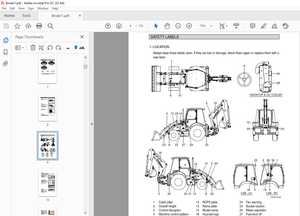
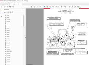
Safety Label Replacement 1194
Battery Specifications 1196
tables 1177
Table 1 Torque Values 1184
Table 2 Weight of Counterweights 1189
Table 3 Battery Specifications* 1196
524238572-0100YRM1200-(11-2006)-UK-EN 1199
toc 1199
Frame 1199
Safety Precautions Maintenance and Repair 1200
General 1203
Description 1203
Overhead Guard Replacement 1205
Remove 1205
Install 1206
Battery and Operator Restraint, Hood and Seat Brake Repair 1207
Battery Restraint and Hood Repair 1207
Operator Restraint System and Seat Assembly 1210
Automatic Locking Retractor (ALR) 1210
Emergency Locking Retractor (ELR) 1210
Seat Brake Repair 1211
Counterweight Replacement 1211
Remove 1211
Install 1212
Traction Motor Repair 1212
Remove 1212
Install 1213
Hydraulic Tank Repair 1214
Inspect 1214
Small Leaks, Repair 1214
Large Leaks, Repair 1214
Clean 1214
Steam Method 1215
Chemical Solution Method 1215
Additional Preparations For Repair 1215
Safety Label Replacement 1216
Battery Specifications 1218
tables 1199
Table 1 Torque Values 1206
Table 2 Weight of Counterweights 1211
Table 3 Battery Specifications* 1218
524238574-8000YRM1201-(02-2010)-UK-EN (2) 1221
toc 1221
Periodic Maintenance 1221
Safety Precautions Maintenance and Repair 1222
General 1227
How to Move Disabled Lift Truck 1227
How to Tow Lift Truck 1227
How to Put Lift Trucks on Blocks 1228
How to Raise Drive Tires 1228
How to Raise Steering Tires 1228
How to Clean a Lift Truck 1229
Maintenance Schedule 1230
Maintenance Procedures Every 8 Hours or Daily 1234
General 1234
How to Make Checks With Key Switch OFF 1235
Tires and Wheels 1235
Forks 1235
Remove 1235
Inspect 1235
Install 1236
Adjust 1236
Inspection of Mast, Mast Pivots, Header Hoses and Lift Chains 1237
Safety Labels 1237
Steering Column Latch 1237
Operator Restraint System 1238
Automatic Locking Retractor (ALR) 1238
Emergency Locking Retractor (ELR) 1238
Battery Restraint System 1239
Battery 1240
Hydraulic System 1241
How to Make Checks With Key Switch ON 1242
Horn, Lights, and Alarm 1242
Steering System 1243
Service Brakes 1243
Parking Brake 1243
Seat Brake 1243
Control Levers and Pedals 1243
Direction and Speed Control Pedals 1243
Lift System Operation 1243
Oil Leaks 1244
First Service After First 100 Hours of Operation 1244
Change Hydraulic Oil and Filter 1244
Lift Truck Models ERC35-55HG (ERC70-120HH) (C839) 1244
Remove 1244
Install 1246
Lift Truck Models ERC35-55HG (ERC70-120HH) (B839) 1247
Remove 1247
Install 1248
Maintenance Procedures Every 500 Hours or 3 Months 1249
Wheel Nuts 1249
Header Hose Checks 1249
Mast Lubrication 1249
Integral Sideshift Carriage 1252
Brake Fluid 1253
Other Lubrication 1253
Maintenance Procedures Every 1000 Hours or 6 Months 1253
Differential and Speed Reducer 1253
Lift Chains 1253
Wear Check 1253
Lubrication 1254
Forks 1254
Parking Brake 1254
Brake Linkage Shafts 1255
Steering Spindles and Tie Rod Ends 1255
Seat Rails 1255
Seat Plate Hinges 1255
Electrical Inspection 1256
Contactors 1256
Maintenance Procedures Every 2000 Hours or Yearly 1258
Brake Fluid 1258
Hydraulic System 1259
Hydraulic Tank Breather, Lift Truck Models ERC35-55HG (ERC70-120 1259
Change Hydraulic Oil and Hydraulic Oil Filter, Lift Truck Models 1259
Remove 1259
Install 1260
Hydraulic Tank Breather, Lift Truck Models ERC35-55HG (ERC70-120 1261
Remove 1261
Install 1261
Change Hydraulic Oil and Hydraulic Oil Filter, Lift Truck Models 1261
Remove 1261
Install 1263
Differential and Speed Reducer 1263
Service Brakes 1264
Wheel Bearings 1264
Steer Wheels, Lubrication 1264
Drive Wheels, Lubrication 1264
Lift Chains 1264
Battery Maintenance 1265
How to Charge Battery 1265
How to Change Battery 1266
Safety Procedures When Working Near Mast 1269
Lift and Tilt System Leak Check 1272
Check Lift Cylinders for Leaks 1272
Check Tilt Cylinders for Leaks 1272
Lift Chain Adjustments 1273
Welding Repairs 1274
Overhead Guard Changes 1275
Wheels and Tires 1275
General 1275
Remove Wheels From Lift Truck 1275
Remove Tire From Wheel and Install Tire on Wheel 1275
Remove 1275
Install 1275
Install Wheels 1276
tables 1221
Table 1 Maintenance Schedule 1231
Table 2 Battery Specifications* 1269
Table 3 Hook-Type Carriage Chain Adjustment 1274
524238574-8000YRM1201-(02-2010)-UK-EN 1279
toc 1279
Periodic Maintenance 1279
Safety Precautions Maintenance and Repair 1280
General 1285
How to Move Disabled Lift Truck 1285
How to Tow Lift Truck 1285
How to Put Lift Trucks on Blocks 1286
How to Raise Drive Tires 1286
How to Raise Steering Tires 1286
How to Clean a Lift Truck 1287
Maintenance Schedule 1288
Maintenance Procedures Every 8 Hours or Daily 1292
General 1292
How to Make Checks With Key Switch OFF 1293
Tires and Wheels 1293
Forks 1293
Remove 1293
Inspect 1293
Install 1294
Adjust 1294
Inspection of Mast, Mast Pivots, Header Hoses and Lift Chains 1295
Safety Labels 1295
Steering Column Latch 1295
Operator Restraint System 1296
Automatic Locking Retractor (ALR) 1296
Emergency Locking Retractor (ELR) 1296
Battery Restraint System 1297
Battery 1298
Hydraulic System 1299
How to Make Checks With Key Switch ON 1300
Horn, Lights, and Alarm 1300
Steering System 1301
Service Brakes 1301
Parking Brake 1301
Seat Brake 1301
Control Levers and Pedals 1301
Direction and Speed Control Pedals 1301
Lift System Operation 1301
Oil Leaks 1302
First Service After First 100 Hours of Operation 1302
Change Hydraulic Oil and Filter 1302
Lift Truck Models ERC35-55HG (ERC70-120HH) (C839) 1302
Remove 1302
Install 1304
Lift Truck Models ERC35-55HG (ERC70-120HH) (B839) 1305
Remove 1305
Install 1306
Maintenance Procedures Every 500 Hours or 3 Months 1307
Wheel Nuts 1307
Header Hose Checks 1307
Mast Lubrication 1307
Integral Sideshift Carriage 1310
Brake Fluid 1311
Other Lubrication 1311
Maintenance Procedures Every 1000 Hours or 6 Months 1311
Differential and Speed Reducer 1311
Lift Chains 1311
Wear Check 1311
Lubrication 1312
Forks 1312
Parking Brake 1312
Brake Linkage Shafts 1313
Steering Spindles and Tie Rod Ends 1313
Seat Rails 1313
Seat Plate Hinges 1313
Electrical Inspection 1314
Contactors 1314
Maintenance Procedures Every 2000 Hours or Yearly 1316
Brake Fluid 1316
Hydraulic System 1317
Hydraulic Tank Breather, Lift Truck Models ERC35-55HG (ERC70-120 1317
Change Hydraulic Oil and Hydraulic Oil Filter, Lift Truck Models 1317
Remove 1317
Install 1318
Hydraulic Tank Breather, Lift Truck Models ERC35-55HG (ERC70-120 1319
Remove 1319
Install 1319
Change Hydraulic Oil and Hydraulic Oil Filter, Lift Truck Models 1319
Remove 1319
Install 1321
Differential and Speed Reducer 1321
Service Brakes 1322
Wheel Bearings 1322
Steer Wheels, Lubrication 1322
Drive Wheels, Lubrication 1322
Lift Chains 1322
Battery Maintenance 1323
How to Charge Battery 1323
How to Change Battery 1324
Safety Procedures When Working Near Mast 1327
Lift and Tilt System Leak Check 1330
Check Lift Cylinders for Leaks 1330
Check Tilt Cylinders for Leaks 1330
Lift Chain Adjustments 1331
Welding Repairs 1332
Overhead Guard Changes 1333
Wheels and Tires 1333
General 1333
Remove Wheels From Lift Truck 1333
Remove Tire From Wheel and Install Tire on Wheel 1333
Remove 1333
Install 1333
Install Wheels 1334
tables 1279
Table 1 Maintenance Schedule 1289
Table 2 Battery Specifications* 1327
Table 3 Hook-Type Carriage Chain Adjustment 1332
524238575-8000YRM1202-(11-2006)-UK-EN (2) 1337
toc 1337
Capacities and Specifications 1337
Safety Precautions Maintenance and Repair 1338
Lift Truck Lifting Capacity 1341
Counterweight Weights 1341
Tire Sizes 1341
Capacities 1342
Hydraulic System 1342
Steering System 1343
Specifications 1343
Turning Radius 1343
Mast Speeds 1344
Maximum Carriage and Tilt Creep Rates 1345
Battery Specifications 1345
Traction Motor Speed 1346
Battery Current at Hoist Relief 1346
Torque Specifications 1346
Brake System 1346
Differential 1347
Drive Axle 1347
Frame 1347
Mast 1347
Main Control Valve 1347
Steering System 1347
Tilt Cylinders 1348
Hydraulic System 1348
Electrical System 1348
tables 1337
Table 1 Manual Control Valve 1342
Table 2 E-Hydraulic Control Valve 1342
524238575-8000YRM1202-(11-2006)-UK-EN 1351
toc 1351
Capacities and Specifications 1351
Safety Precautions Maintenance and Repair 1352
Lift Truck Lifting Capacity 1355
Counterweight Weights 1355
Tire Sizes 1355
Capacities 1356
Hydraulic System 1356
Steering System 1357
Specifications 1357
Turning Radius 1357
Mast Speeds 1358
Maximum Carriage and Tilt Creep Rates 1359
Battery Specifications 1359
Traction Motor Speed 1360
Battery Current at Hoist Relief 1360
Torque Specifications 1360
Brake System 1360
Differential 1361
Drive Axle 1361
Frame 1361
Mast 1361
Main Control Valve 1361
Steering System 1361
Tilt Cylinders 1362
Hydraulic System 1362
Electrical System 1362
tables 1351
Table 1 Manual Control Valve 1356
Table 2 E-Hydraulic Control Valve 1356
524238576-8000YRM1203-(02-2009)-UK-EN (2) 1365
toc 1365
Diagrams 1365
Safety Precautions Maintenance and Repair 1366
524238576-8000YRM1203-(02-2009)-UK-EN 1405
toc 1405
Diagrams 1405
Safety Precautions Maintenance and Repair 1406
524256687-2000YRM1224-(04-2008)-UK-EN (2) 1445
toc 1445
Electro-hydraulic Control Valve 1445
Safety Precautions Maintenance and Repair 1446
General 1449
Description 1449
Electro-Hydraulic Control System 1449
Electro-Hydraulic Control Valve 1452
Electro-Hydraulic Valve Driver Module 1468
Mini-Lever Module (MLM) 1468
Joystick 1469
Electro-Hydraulic Control Valve Repair 1470
Remove 1470
Disassemble 1479
Solenoid Coil Replacement 1481
Cartridge Replacement 1483
Electro-Hydraulic Pressure Reducing Valve (EHPR) Replacement 1484
Lift Circuit Check Valve Replacement 1485
Compensator Cartridge Replacement 1485
Primary and Secondary Relief Valves Replacement 1485
Tilt Counterbalance Valve Replacement 1486
Flow Regulator Valve Replacement 1486
Assemble 1486
Install 1486
E-Hydraulics Calibration 1495
Mini-Lever Module 1497
Mini-Lever Module (MLM) 1497
Remove 1497
Install 1497
Mini-Lever Replacement 1497
Remove 1497
Clean and Inspect 1498
Install 1498
Push Button Switch Replacement 1499
Remove 1499
Install 1500
Test 1501
Mini-levers 1501
Full Stroke Test 1501
Function Returns to Neutral Test 1501
Push Button Switch 1502
Joystick 1502
Remove and Disassemble 1502
Inspect 1502
Assemble and Install 1502
Troubleshooting 1503
tables 1445
Table 1 Primary and Secondary Relief Valve Values 1455
Table 2 Solenoid Resistance Values 1481
Table 3 Cartridge and Solenoid Coil Nut Torque for Lift truck M 1484
Table 4 Cartridge and Solenoid Coil Nut Torque for Lift truck M 1484
524256687-2000YRM1224-(04-2008)-UK-EN 1515
toc 1515
Electro-hydraulic Control Valve 1515
Safety Precautions Maintenance and Repair 1516
General 1519
Description 1519
Electro-Hydraulic Control System 1519
Electro-Hydraulic Control Valve 1522
Electro-Hydraulic Valve Driver Module 1538
Mini-Lever Module (MLM) 1538
Joystick 1539
Electro-Hydraulic Control Valve Repair 1540
Remove 1540
Disassemble 1549
Solenoid Coil Replacement 1551
Cartridge Replacement 1553
Electro-Hydraulic Pressure Reducing Valve (EHPR) Replacement 1554
Lift Circuit Check Valve Replacement 1555
Compensator Cartridge Replacement 1555
Primary and Secondary Relief Valves Replacement 1555
Tilt Counterbalance Valve Replacement 1556
Flow Regulator Valve Replacement 1556
Assemble 1556
Install 1556
E-Hydraulics Calibration 1565
Mini-Lever Module 1567
Mini-Lever Module (MLM) 1567
Remove 1567
Install 1567
Mini-Lever Replacement 1567
Remove 1567
Clean and Inspect 1568
Install 1568
Push Button Switch Replacement 1569
Remove 1569
Install 1570
Test 1571
Mini-levers 1571
Full Stroke Test 1571
Function Returns to Neutral Test 1571
Push Button Switch 1572
Joystick 1572
Remove and Disassemble 1572
Inspect 1572
Assemble and Install 1572
Troubleshooting 1573
tables 1515
Table 1 Primary and Secondary Relief Valve Values 1525
Table 2 Solenoid Resistance Values 1551
Table 3 Cartridge and Solenoid Coil Nut Torque for Lift truck M 1554
Table 4 Cartridge and Solenoid Coil Nut Torque for Lift truck M 1554
524265342-4000YRM1250-(06-2021)-UK-EN 1585
Safety Procedures When Working Near Mast 1591
Fork Replacement 1594
Remove, Lift Trucks Not Equipped With Fork Positioner Or Equipped With Fork Positioner Before August, 2012 1594
Remove, Lift Trucks Manufactured After August, 2012 And Equipped With Fork Positioner 1595
Remove, Lift Truck Models Equipped With Fork Positioner and Manufactured After March, 2017GLC40, 45, 55VX, GLC55SVX (GC/GLC080, 100, 120VX, GC/GLC80, 100VXBCS, GC/GLC120SVX, GC/GLC120VXPRS (G818) and GLP/GDP40VX5/VX6, GLP/GDP45SVX5, GLP/GDP45VX6, GLP/GDP50-55VX (GP/GLP/GDP080, 090, 100, 110, 120VX (K813) 1597
Install, Lift Trucks Not Equipped With Fork Positioner Or Equipped With Fork Positioner Before August, 2012 1598
Install, Lift Trucks Manufactured After August, 2012 And Equipped With Fork Positioner 1599
Install, Lift Truck Models Equipped With Fork Positioner and Manufactured After March, 2017 GLC40, 45, 55VX, GLC55SVX (GC/GLC080, 100, 120VX, GC/GLC80, 100VXBCS, GC/GLC120SVX, GC/GLC120VXPRS (G818) and GLP/GDP40VX5/VX6, GLP/GDP45SVX5, GLP/GDP45VX6, GLP/GDP50-55VX (GP/GLP/GDP080, 090, 100, 110, 120VX (K813) 1600
Checks, Lift Trucks Not Equipped With Fork Positioner Or Equipped With Fork Positioner Before August, 2012 1600
Checks, Lift Truck Models Equipped With Fork Positioner and Manufactured After March, 2017GLC40, 45, 55VX, GLC55SVX (GC/GLC080, 100, 120VX, GC/GLC80, 100VXBCS, GC/GLC120SVX, GC/GLC120VXPRS (G818) and GLP/GDP40VX5/VX6, GLP/GDP45SVX5, GLP/GDP45VX6, GLP/GDP50-55VX (GP/GLP/GDP080, 090, 100, 110, 120VX (K813) 1601
Checks, Lift Trucks Manufactured After August, 2012 And Equipped With Fork Positioner 1602
Fixed Carriage Replacement 1604
Remove, Carriage With Hook Forks 1604
Remove, Carriage With Pin Type Forks Lift Truck Models GLP/GDP60VX, GLP/GDP70VX (GP/GLP/GDP135VX, GP/GLP/GDP155VX) (C878, D878, E878) 1612
Install, Carriage With Hook Forks 1613
Install, Carriage With Pin Type Forks Lift Truck Models GLP/GDP60VX, GLP/GDP70VX (GP/GLP/GDP135VX, GP/GLP/GDP155VX) (C878, D878, E878) 1613
Disconnecting Attachment Hydraulic Quick Disconnect Hoses 1614
Connecting Attachment Hydraulic Quick Disconnect Hoses 1614
Integral Sideshift Carriage Repair 1615
Remove, for lift truck models ERC35-55HG (ERC70-120HH) (C839), GLC40, 45, 55VX; GLC55SVX; (GC/GLC080, 100, 120VX; GC/GLC080, 100VXBCS; GC/GLC120SVX; GC/GLC120VXPRS) (E818, F818, G818) and GLP/GDP40VX5/VX6; GLP/GDP45SVX5, GLP/GDP45VX6; GLP/GDP50-55VX (GP/GLP/GDP080, 090, 100, 110, 120VX) (F813, G813, H813, J813, K813) 1615
Disassemble 1615
Clean and Inspect 1618
Assemble 1618
Install, for lift truck models ERC35-55HG (ERC70-120HH) (C839), GLC40, 45, 55VX; GLC55SVX; (GC/GLC080, 100, 120VX; GC/GLC080, 100VXBCS; GC/GLC120SVX; GC/GLC120VXPRS) (E818, F818, G818) and GLP/GDP40VX5/VX6; GLP/GDP45SVX5, GLP/GDP45VX6; GLP/GDP50-55VX (GP/GLP/GDP080, 090, 100, 110, 120VX) (F813, G813, H813, J813, K813) 1619
Hang On Sideshift Carriage Repair 1620
Remove, Lift Truck Models GLP/GDP60VX, GLP/GDP70VX (GP/GLP/GDP135VX, GP/GLP/GDP155VX) (C878, D878, E878) and GC/GLC/GDC60VX, GC/GLC/GDC70VX (GC/GLC/GDC135VX, GC/GLC/GDC155VX) (C879, D879, E879, F879, G879) 1620
Disassemble 1632
Clean and Inspect 1641
Assemble 1642
Install 1643
Hang-On Sideshift Carriage Repair 1645
Remove 1645
Disassemble Carriage 1647
Clean and Inspect 1650
Assemble 1650
Install 1653
Fork Positioner 1656
Two-Stage Mast With Limited Free-Lift Repair 1657
Remove 1657
Disassemble 1660
Clean and Inspect 1663
Assemble 1681
Install, Lift Truck ModelsGLP/GDP40VX5/VX6; GLP/GDP45SVX5, GLP/GDP45VX6; GLP/GDP50-55VX (GP/GLP/GDP080, 090, 100, 110, 120VX) (F813, G813, H813, J813, K813) and GLP/GDP60VX, GLP/GDP70VX (GP/GLP/GDP135VX, GP/GLP/GDP155VX) (C878, D878, E878) 1683
Install, Lift Trucks ModelsGLC40, 45, 55VX; GLC55SVX; (GC/GLC080, 100, 120VX; GC/GLC080, 100VXBCS; GC/GLC120SVX; GC/GLC120VXPRS) (E818, F818, G818) GLC/GDC60VX, GLC/GDC70VX, (GC/GLC/GDC135VX, GC/GLC/GDC155VX) (C879, D879, E879, F879, G879), and ERC35-55HG (ERC70-120HH) (C839) 1685
Header Hose Alignment 1696
Two-Stage Mast With Full Free-Lift Repair 1707
Remove 1707
Disassemble 1709
Clean and Inspect 1720
Assemble 1721
Install, Lift Truck ModelsGLP/GDP40VX5/VX6; GLP/GDP45SVX5, GLP/GDP45VX6; GLP/GDP50-55VX (GP/GLP/GDP080, 090, 100, 110, 120VX) (F813, G813, H813, J813, K813) 1723
Install, Lift Trucks ModelsGLC40, 45, 55VX; GLC55SVX; (GC/GLC080, 100, 120VX; GC/GLC080, 100VXBCS; GC/GLC120SVX; GC/GLC120VXPRS) (E818, F818, G818) and ERC35-55HG (ERC70-120HH) (C839) 1726
Header Hose Installation and Adjustment 1730
Installation 1730
Adjustment 1731
Three-Stage Mast With Full Free-Lift Repair 1732
Remove 1732
Disassemble 1734
Clean and Inspect 1764
Assemble 1766
Install, Lift Truck ModelsGLP/GDP40VX5/VX6; GLP/GDP45SVX5, GLP/GDP45VX6; GLP/GDP50-55VX (GP/GLP/GDP080, 090, 100, 110, 120VX) (F813, G813, H813, J813, K813) and GLP/GDP60VX, GLP/GDP70VX, (GP/GLP/GDP135VX, GP/GLP/GDP155VX) (C878, D878, E878) 1769
Install, Lift Trucks ModelsGLC40, 45, 55VX; GLC55SVX; (GC/GLC080, 100, 120VX; GC/GLC080, 100VXBCS; GC/GLC120SVX; GC/GLC120VXPRS) (E818, F818, G818), GC/GLC/GDC60VX, GC/GLC/GDC70VX, (GC/GLC/GDC135VX, GC/GLC/GDC155VX) (C879, D879, E879, F879, G879), and ERC35-55HG (ERC70-120HH) (C839) 1774
Header Hose Alignment for GLC40, 45, 55VX; GLC55SVX; (GC/GLC080, 100, 120VX; GC/GLC080, 100VXBCS; GC/GLC120SVX; GC/GLC120VXPRS) (E818, F818, G818), GLP/GDP40VX5/VX6; GLP/GDP45SVX5, GLP/GDP45VX6; GLP/GDP50-55VX (GP/GLP/GDP080, 090, 100, 110, 120VX) (F813, G813, H813, J813, K813), and ERC35-55HG (ERC70-120HH) (C839) 1781
Header Hose Alignment for GLP/GDP60VX, GLP/GDP70VX (GP/GLP/GDP135VX, GP/GLP/GDP155VX) (C878, D878, E878) and GC/GLC/GDC60VX, GC/GLC/GDC70VX, (GC/GLC/GDC135VX, GC/GLC/GDC155VX) (C879, D879, E879, F879, G879) 1788
Mast Operation Check 1792
Tilt Cylinder Adjustment 1793
Lift Chains Adjustment 1793
Mast Adjustments 1795
Load Roller Adjustment 1795
Mast Side Kicking Adjustment 1797
Shimming The Mast Mounting Pin, Lift Truck Models GP/GLP/GDP080, 090, 100, 110, 120VX (F813, G813, H813, K813) 1798
Carriage Adjustments 1800
Series Code / Model Designation Reference Table 1801
524265342-4000YRM1250-(09-2018)-UK-EN 1805
Safety Procedures When Working Near Mast 1811
Fork Replacement 1813
Remove, Lift Trucks Not Equipped With Fork Positioner Or Equipped With Fork Positioner Before August, 2012 1813
Remove, Lift Trucks Manufactured After August, 2012 And Equipped With Fork Positioner 1815
Remove, Lift Truck Models Equipped With Fork Positioner and Manufactured After March, 2017GLC40, 45, 55VX, GLC55SVX (GC/GLC080, 100, 120VX, GC/GLC80, 100VXBCS, GC/GLC120SVX, GC/GLC120VXPRS (G818) and GLP/GDP40VX5/VX6, GLP/GDP45SVX5, GLP/GDP45VX6, GLP/GDP50-55VX (GP/GLP/GDP080, 090, 100, 110, 120VX (K813) 1816
Install, Lift Trucks Not Equipped With Fork Positioner Or Equipped With Fork Positioner Before August, 2012 1817
Install, Lift Trucks Manufactured After August, 2012 And Equipped With Fork Positioner 1818
Install, Lift Truck Models Equipped With Fork Positioner and Manufactured After March, 2017 GLC40, 45, 55VX, GLC55SVX (GC/GLC080, 100, 120VX, GC/GLC80, 100VXBCS, GC/GLC120SVX, GC/GLC120VXPRS (G818) and GLP/GDP40VX5/VX6, GLP/GDP45SVX5, GLP/GDP45VX6, GLP/GDP50-55VX (GP/GLP/GDP080, 090, 100, 110, 120VX (K813) 1819
Checks, Lift Trucks Not Equipped With Fork Positioner Or Equipped With Fork Positioner Before August, 2012 1819
Checks, Lift Truck Models Equipped With Fork Positioner and Manufactured After March, 2017GLC40, 45, 55VX, GLC55SVX (GC/GLC080, 100, 120VX, GC/GLC80, 100VXBCS, GC/GLC120SVX, GC/GLC120VXPRS (G818) and GLP/GDP40VX5/VX6, GLP/GDP45SVX5, GLP/GDP45VX6, GLP/GDP50-55VX (GP/GLP/GDP080, 090, 100, 110, 120VX (K813) 1821
Checks, Lift Trucks Manufactured After August, 2012 And Equipped With Fork Positioner 1821
Fixed Carriage Replacement 1823
Remove, Carriage With Hook Forks 1823
Remove, Carriage With Pin Type Forks Lift Truck Models GLP/GDP60VX, GLP/GDP70VX (GP/GLP/GDP135VX, GP/GLP/GDP155VX) (C878, D878, E878) 1832
Install, Carriage With Hook Forks 1833
Install, Carriage With Pin Type Forks Lift Truck Models GLP/GDP60VX, GLP/GDP70VX (GP/GLP/GDP135VX, GP/GLP/GDP155VX) (C878, D878, E878) 1833
Disconnecting Attachment Hydraulic Quick Disconnect Hoses 1834
Connecting Attachment Hydraulic Quick Disconnect Hoses 1834
Integral Sideshift Carriage Repair 1835
Remove, for lift truck models ERC35-55HG (ERC70-120HH) (C839), GLC40, 45, 55VX; GLC55SVX; (GC/GLC080, 100, 120VX; GC/GLC080, 100VXBCS; GC/GLC120SVX; GC/GLC120VXPRS) (E818, F818, G818) and GLP/GDP40VX5/VX6; GLP/GDP45SVX5, GLP/GDP45VX6; GLP/GDP50-55VX (GP/GLP/GDP080, 090, 100, 110, 120VX) (F813, G813, H813, J813, K813) 1835
Disassemble 1835
Clean and Inspect 1838
Assemble 1838
Install, for lift truck models ERC35-55HG (ERC70-120HH) (C839), GLC40, 45, 55VX; GLC55SVX; (GC/GLC080, 100, 120VX; GC/GLC080, 100VXBCS; GC/GLC120SVX; GC/GLC120VXPRS) (E818, F818, G818) and GLP/GDP40VX5/VX6; GLP/GDP45SVX5, GLP/GDP45VX6; GLP/GDP50-55VX (GP/GLP/GDP080, 090, 100, 110, 120VX) (F813, G813, H813, J813, K813) 1839
Hang On Sideshift Carriage Repair 1839
Remove, Lift Truck Models GLP/GDP60VX, GLP/GDP70VX (GP/GLP/GDP135VX, GP/GLP/GDP155VX) (C878, D878, E878) and GLC/GDC60VX, GLC/GDC70VX (GC/GLC/GDC135VX, GC/GLC/GDC155VX) (C879, D879, E879, F879) 1839
Disassemble 1851
Clean and Inspect 1860
Assemble 1861
Install 1862
Bolzoni Hang-On Sideshift Carriage Repair 1864
Remove 1864
Disassemble Carriage 1866
Clean and Inspect 1869
Assemble 1869
Install 1872
Fork Positioner 1874
Two-Stage Mast With Limited Free-Lift Repair 1875
Remove 1875
Disassemble 1879
Clean and Inspect 1882
Assemble 1899
Install, Lift Truck ModelsGLP/GDP40VX5/VX6; GLP/GDP45SVX5, GLP/GDP45VX6; GLP/GDP50-55VX (GP/GLP/GDP080, 090, 100, 110, 120VX) (F813, G813, H813, J813, K813) and GLP/GDP60VX, GLP/GDP70VX (GP/GLP/GDP135VX, GP/GLP/GDP155VX) (C878, D878, E878) 1901
Install, Lift Trucks ModelsGLC40, 45, 55VX; GLC55SVX; (GC/GLC080, 100, 120VX; GC/GLC080, 100VXBCS; GC/GLC120SVX; GC/GLC120VXPRS) (E818, F818, G818) GLC/GDC60VX, GLC/GDC70VX, (GC/GLC/GDC135VX, GC/GLC/GDC155VX) (C879, D879, E879, F879), and ERC35-55HG (ERC70-120HH) (C839) 1902
Header Hose Alignment 1914
Two-Stage Mast With Full Free-Lift Repair 1924
Remove 1924
Disassemble 1926
Clean and Inspect 1938
Assemble 1939
Install, Lift Truck ModelsGLP/GDP40VX5/VX6; GLP/GDP45SVX5, GLP/GDP45VX6; GLP/GDP50-55VX (GP/GLP/GDP080, 090, 100, 110, 120VX) (F813, G813, H813, J813, K813) 1941
Install, Lift Trucks ModelsGLC40, 45, 55VX; GLC55SVX; (GC/GLC080, 100, 120VX; GC/GLC080, 100VXBCS; GC/GLC120SVX; GC/GLC120VXPRS) (E818, F818, G818) and ERC35-55HG (ERC70-120HH) (C839) 1944
Header Hose Installation and Adjustment 1948
Installation 1948
Adjustment 1948
Three-Stage Mast With Full Free-Lift Repair 1949
Remove 1949
Disassemble 1951
Clean and Inspect 1981
Assemble 1982
Install, Lift Truck ModelsGLP/GDP40VX5/VX6; GLP/GDP45SVX5, GLP/GDP45VX6; GLP/GDP50-55VX (GP/GLP/GDP080, 090, 100, 110, 120VX) (F813, G813, H813, J813, K813) and GLP/GDP60VX, GLP/GDP70VX, (GP/GLP/GDP135VX, GP/GLP/GDP155VX) (C878, D878, E878) 1986
Install, Lift Trucks ModelsGLC40, 45, 55VX; GLC55SVX; (GC/GLC080, 100, 120VX; GC/GLC080, 100VXBCS; GC/GLC120SVX; GC/GLC120VXPRS) (E818, F818, G818), GLC/GDC60VX, GLC/GDC70VX, (GC/GLC/GDC135VX, GC/GLC/GDC155VX) (C879, D879, E879, F879), and ERC35-55HG (ERC70-120HH) (C839) 1991
Header Hose Alignment for GLC40, 45, 55VX; GLC55SVX; (GC/GLC080, 100, 120VX; GC/GLC080, 100VXBCS; GC/GLC120SVX; GC/GLC120VXPRS) (E818, F818, G818), GLP/GDP40VX5/VX6; GLP/GDP45SVX5, GLP/GDP45VX6; GLP/GDP50-55VX (GP/GLP/GDP080, 090, 100, 110, 120VX) (F813, G813, H813, J813, K813), and ERC35-55HG (ERC70-120HH) (C839) 1998
Header Hose Alignment for GLP/GDP60VX, GLP/GDP70VX (GP/GLP/GDP135VX, GP/GLP/GDP155VX) (C878, D878, E878) and GLC/GDC60VX, GLC/GDC70VX, (GC/GLC/GDC135VX, GC/GLC/GDC155VX) (C879, D879, E879, F879) 2004
Mast Operation Check 2008
Tilt Cylinder Adjustment 2008
Lift Chains Adjustment 2009
Mast Adjustments 2010
Load Roller Adjustment 2010
Mast Side Kicking Adjustment 2012
Shimming The Mast Mounting Pin, Lift Truck Models GP/GLP/GDP080, 090, 100, 110, 120VX (F813, G813, H813, K813) 2013
Carriage Adjustments 2016
More products