$40.95
Yale Forklift C883 (ESC030AD, ESC035AD, ESC040AD) Service Manual PDF
Yale Forklift C883 (ESC030AD, ESC035AD, ESC040AD) Service Manual – PDF DOWNLOAD
FILE DETAILS:
Yale Forklift C883 (ESC030AD, ESC035AD, ESC040AD) Service Manual – PDF DOWNLOAD
Language : English
Pages : 1688
Downloadable : Yes
File Type : PDF
IMAGES PREVIEW OF THE MANUAL:
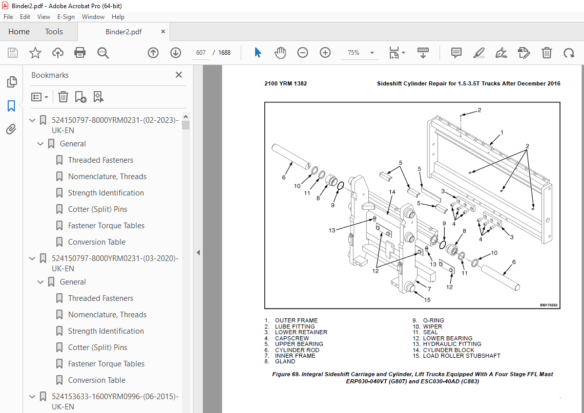
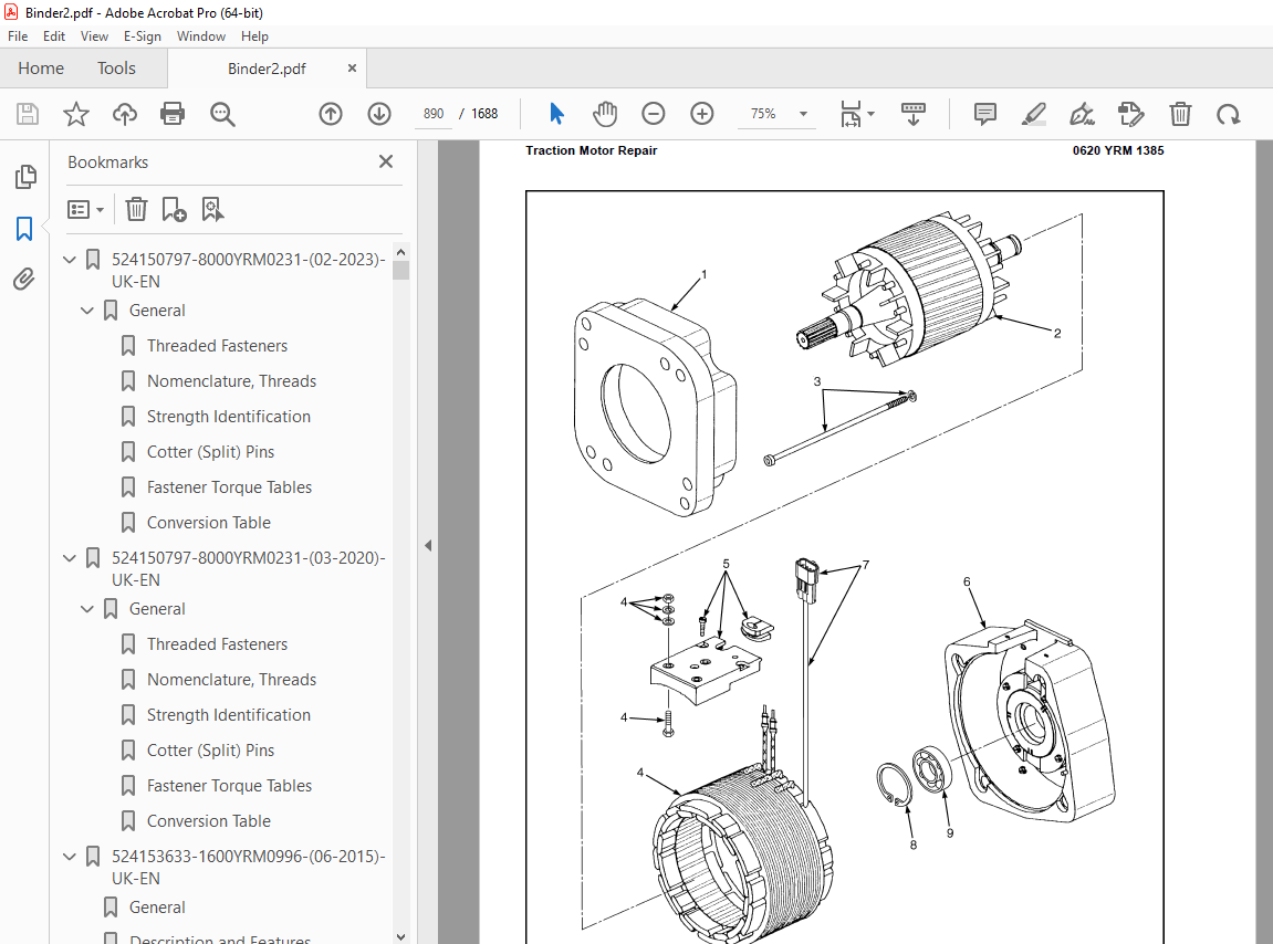
TABLE OF CONTENTS:
Yale Forklift C883 (ESC030AD, ESC035AD, ESC040AD) Service Manual – PDF DOWNLOAD
524150797-8000YRM0231-(02-2023)-UK-EN 1
General 7
Threaded Fasteners 7
Nomenclature, Threads 7
Strength Identification 8
Cotter (Split) Pins 9
Fastener Torque Tables 14
Conversion Table 16
524150797-8000YRM0231-(03-2020)-UK-EN 23
General 27
Threaded Fasteners 27
Nomenclature, Threads 27
Strength Identification 28
Cotter (Split) Pins 29
Fastener Torque Tables 34
Conversion Table 36
524153633-1600YRM0996-(06-2015)-UK-EN 43
General 47
Description and Features 47
On-Demand Steering Circuit 47
Description 48
A883 48
B883 / C883
49
Steering Control Handle 50
Remove 50
Install 50
Steering Sensor 50
Test 50
Remove 50
Install 50
Steering Control Unit (SCU) 51
Description 51
Inspect 51
Remove 51
Repair 53
Replace 53
Steering Pump and Motor Assembly 54
Description 54
Inspect 54
Remove 54
Repair 55
Disassemble 55
Assemble 56
Install 57
Power Steering Pump 57
Description 57
Repair 57
Disassemble 57
Assemble 58
Steer Unit Actuator-Kordel™ 59
Description 59
Inspect 59
Steering Actuator 59
Remove 59
Disassemble 61
Clean 61
Inspect 61
Assemble 63
Install 64
Steer Tire and Wheel 64
Remove 64
Install 65
Wheel Hub 65
Remove 65
Clean 65
Inspect 66
Install 66
Checks and Adjustments 66
Air in System 66
Operation Check 67
Steering Pressure 67
Troubleshooting 68
524158039-0620YRM0294-(09-2016)-UK-EN 73
General 77
Brush and Commutator Inspection 78
Hydraulic Pump Motor and Traction Motor 78
Steering Pump Motor 81
Normal Commutator Surface 81
Commutator Problems 81
Brush Replacement 86
Stoning the Commutator 89
Motors Repair 90
Disassemble 91
Traction Motor and Hydraulic Pump Motor 91
Steering Pump Motor 92
Assemble 96
Traction Motor and Hydraulic Pump Motor 96
Steering Pump Motor 98
Brush Alignment, Traction and Hydraulic Motors 100
Tests for Damaged Field and Armature 101
Test for an Open Circuit in One Armature Winding 101
Test for Short Circuit in One Armature Winding 101
Test for Short Circuit to Armature Shaft 102
Test for Open Circuit in Field Coil 102
Test for Short Circuit in Field Coil 103
Test for Short Circuit Between Field and Motor Case 103
Brush Holder Test 103
Troubleshooting 104
524158040-2240YRM0001-(01-2023)-UK-EN 109
General 115
Battery Type 115
Lead-Acid Batteries 115
Lithium-Ion Batteries 116
Specific Gravity 116
Chemical Reaction in a Cell 116
Electrical Terms 118
Battery Selection 119
Battery Voltage 120
Battery as a Counterweight 120
Battery Ratings 120
Kilowatt-Hours 120
Battery Maintenance 121
Safety Procedures 121
Maintenance Records 121
New Battery 121
Cleaning Battery 122
Adding Water to Battery 124
Hydrometer 124
Battery Temperature 125
Charging Battery 126
Types of Battery Charges 127
Methods of Charging 128
Troubleshooting Charger 129
Knowing When Battery Is Fully Charged 129
Where to Charge Batteries 129
Equipment Needed 129
Battery Connectors 130
Battery Care 130
Troubleshooting 132
524158040-2240YRM0001-(03-2020)-UK-EN 137
General 141
Battery Type 141
Lead-Acid Batteries 141
Lithium-Ion Batteries 142
Specific Gravity 142
Chemical Reaction in a Cell 142
Electrical Terms 144
Battery Selection 144
Battery Voltage 145
Battery as a Counterweight 146
Battery Ratings 146
Kilowatt-Hours 146
Battery Maintenance 146
Safety Procedures 146
Maintenance Records 147
New Battery 147
Cleaning Battery 147
Adding Water to Battery 149
Hydrometer 150
Battery Temperature 151
Charging Battery 152
Types of Battery Charges 152
Methods of Charging 154
Troubleshooting Charger 154
Knowing When Battery Is Fully Charged 155
Where to Charge Batteries 155
Equipment Needed 155
Battery Connectors 156
Battery Care 156
Troubleshooting 158
524223769-2200YRM1128-(01-2023)-UK-EN 163
Series Code / Model Designation Reference Table 171
General 173
Deutsch Crimping Tool 174
How to Strip a Wire for Use With Deutsch Crimping Tool 174
How to Crimp With the Deutsch Crimping Tool 175
Calibration Test for the Deutsch Crimping Tool 177
Deutsch Connectors 179
DT, DTM, and DTP Series Connectors 179
HD Series Connectors 222
Metri-Pack Connectors 244
Remove and Install 244
Micro-Pack Connectors 247
Weather-Pack Connectors 248
AMPSEAL Crimping Tools 250
AMP Hand Crimping Tool With Certi-Crimp 250
Description 250
Stripping Wire for Use with AMP Hand Crimping Tool 251
Insulation Crimp Adjustment 252
Maintenance and Inspection for AMP Hand Crimping Tool 252
AMP Hand Crimping Tool 252
Crimp Height Inspection 252
How to use AMP Hand Crimping Tool 253
AMP Pro-Crimper II Tool 253
Description 253
Remove and Install Die Set and Locator Assembly 254
Stripping Wire for Use With AMP PRO-CRIMPER II Tool 254
Contact Support Adjustment 255
Crimp Height Adjustment 256
Maintenance and Inspection Procedures 256
PRO-CRIMPER II Tool 256
Crimp Height Inspection 256
How to Use AMP PRO-CRIMPER II Tool 257
AMPSEAL Connector Assemblies 258
Description for Plug Connector Assembly 258
Seal Plug 259
Contact Crimping 259
Description for Plug Connector and Header Assembly 264
Voltage Reading 267
Seal Plug 267
Contact Crimping 267
AMP Superseal 1 5 Crimping Tools 274
Mini Mic Receptacle and Tab Contacts 274
Description 274
Crimping Conditions and Measurements 274
Insertion of Rubber Seal on Cable 276
AMP Hand Application Tool 281
Description 281
Maintenance and Inspection 281
Crimp Height Inspection 281
Crimp Height Adjustment 282
How to Use AMP Hand Application Tool 282
AMP Pro-Crimper II Tool 283
Description 283
Remove and Install Die Set and Locator Assembly 283
Adjustments 284
Contact Support 284
Crimp Height 285
Inspections and Maintenance 286
Crimp Height Inspection 286
Visual Inspection 286
Maintenance 287
How to Use Pro-Crimper II Tool 287
AMP Superseal 1 5 Connector Assemblies 288
Description 288
Repair and Maintenance 295
Panel Mount Option 295
AMP Fastin-Faston Hand Tools 296
Description – AMP Double Action Hand Tool 296
Maintenance and Inspection Procedures 296
Daily Maintenance 296
Periodic Tool Inspection 297
Lubrication 297
Visual Inspection 297
Crimp Height Inspection 297
Certi-Crimp Ratchet Inspection 298
How to Use AMP Double Action Hand Tool 299
Description – AMP Extraction Tool 300
Maintenance and Inspection 301
How to Use AMP Extraction Tool 301
AMP Fastin-Faston Receptacles and Housings 303
Description 303
Wire Repair 311
Wire Splicing Requirements 311
Deutsch Jiffy Splice 312
Twisted/Shielded Cable and Leads Repair 318
Special Tools 320
524223769-2200YRM1128-(07-2020)-UK-EN 329
Series Code / Model Designation Reference Table 335
General 338
Deutsch Crimping Tool 338
How to Strip a Wire for Use With Deutsch Crimping Tool 338
How to Crimp With the Deutsch Crimping Tool 339
Calibration Test for the Deutsch Crimping Tool 341
Deutsch Connectors 343
DT, DTM, and DTP Series Connectors 343
HD Series Connectors 385
Metri-Pack Connectors 408
Remove and Install 408
Micro-Pack Connectors 410
Weather-Pack Connectors 411
AMPSEAL Crimping Tools 413
AMP Hand Crimping Tool With Certi-Crimp 413
Description 413
Stripping Wire for Use with AMP Hand Crimping Tool 413
Insulation Crimp Adjustment 414
Maintenance and Inspection for AMP Hand Crimping Tool 414
AMP Hand Crimping Tool 414
Crimp Height Inspection 414
How to use AMP Hand Crimping Tool 415
AMP Pro-Crimper II Tool 415
Description 415
Remove and Install Die Set and Locator Assembly 416
Stripping Wire for Use With AMP PRO-CRIMPER II Tool 417
Contact Support Adjustment 417
Crimp Height Adjustment 418
Maintenance and Inspection Procedures 418
PRO-CRIMPER II Tool 418
Crimp Height Inspection 418
How to Use AMP PRO-CRIMPER II Tool 419
AMPSEAL Connector Assemblies 420
Description for Plug Connector Assembly 420
Seal Plug 421
Contact Crimping 421
Description for Plug Connector and Header Assembly 426
Voltage Reading 428
Seal Plug 428
Contact Crimping 428
AMP Superseal 1 5 Crimping Tools 435
Mini Mic Receptacle and Tab Contacts 435
Description 435
Crimping Conditions and Measurements 435
Insertion of Rubber Seal on Cable 437
AMP Hand Application Tool 442
Description 442
Maintenance and Inspection 442
Crimp Height Inspection 442
Crimp Height Adjustment 443
How to Use AMP Hand Application Tool 443
AMP Pro-Crimper II Tool 444
Description 444
Remove and Install Die Set and Locator Assembly 445
Adjustments 445
Contact Support 445
Crimp Height 446
Inspections and Maintenance 447
Crimp Height Inspection 447
Visual Inspection 447
Maintenance 448
How to Use Pro-Crimper II Tool 448
AMP Superseal 1 5 Connector Assemblies 449
Description 449
Repair and Maintenance 456
Panel Mount Option 456
AMP Fastin-Faston Hand Tools 457
Description – AMP Double Action Hand Tool 457
Maintenance and Inspection Procedures 457
Daily Maintenance 457
Periodic Tool Inspection 458
Lubrication 458
Visual Inspection 458
Crimp Height Inspection 458
Certi-Crimp Ratchet Inspection 459
How to Use AMP Double Action Hand Tool 460
Description – AMP Extraction Tool 461
Maintenance and Inspection 461
How to Use AMP Extraction Tool 462
AMP Fastin-Faston Receptacles and Housings 463
Description 463
Wire Repair 470
Wire Splicing Requirements 470
Deutsch Jiffy Splice 471
Twisted/Shielded Cable and Leads Repair 476
Special Tools 479
524319496-2100YRM1382-(02-2018)-UK-EN 487
Safety Procedures When Working Near Mast 495
General 497
Description 498
Tilt Cylinder Repair for 2 0-5 5T Trucks 498
Remove 498
Disassemble 500
Inspect 501
Clean 501
Assemble 501
Install 503
Tilt Cylinders, Adjust 503
Tilt Cylinder Leak Check 506
Tilt Cylinder Repair
for 1 0-2 0T Trucks 507
Remove 507
Disassemble 509
Inspect 511
Clean 511
Assemble 511
Install 511
Tilt Cylinders, Adjust 512
Tilt Cylinders Leak Check 513
Lift Cylinder Repair
for 2 0-3 5T Trucks 514
Main Lift Cylinders 514
Remove 514
Two-Stage FFL 514
Three-Stage FFL 516
Four-Stage FFL 516
Two-Stage LFL 517
Disassemble 517
Two-Stage FFL 517
Three-Stage FFL 519
Four-Stage FFL 519
Two-Stage LFL 521
Clean 522
Inspect 522
Assemble 522
Two-Stage FFL 522
Three-Stage FFL 522
Four-Stage FFL 523
Two-Stage LFL 523
Install 524
Two-Stage FFL 524
System Air Bleed Procedures 524
Three-Stage FFL 524
Four-Stage FFL 525
Two-Stage LFL 525
Lift Cylinder Repair for Lift Truck Model ERP15VT (G807) 526
Main Lift Cylinder 526
Remove 526
Main Lift Cylinders – Two-Stage FFL Mast 526
Left-Hand Main Lift Cylinder – Three-Stage FFL Mast 528
Right-Hand Main Lift Cylinder – Three-Stage FFL Mast 532
Main Lift Cylinder – Two-Stage LFL Mast 532
Disassemble 535
Main Lift Cylinders – Two-Stage FFL Mast 535
Main Lift Cylinder – Three-Stage FFL Mast 537
Main Lift Cylinder – Two-Stage LFL Mast 537
Clean 538
Inspect 538
Assemble 539
Main Lift Cylinder – Two-Stage FFL Mast 539
Main Lift Cylinder – Three-Stage FFL Mast 539
Main Lift Cylinder – Two-Stage LFL Mast 539
Install 540
Main Lift Cylinder – Two-Stage FFL Mast 540
Left-Hand Main Lift Cylinder – Three-Stage FFL Mast 540
Right-Hand Main Lift Cylinder – Three-Stage FFL Mast 541
Main Lift Cylinder – Two-Stage LFL Mast 542
System Air Bleed Procedures 543
All Main Lift Cylinders 543
Lift Cylinder Repair for 1 5-2 0T Trucks 543
Main Lift Cylinder 543
Remove 543
Two-Stage FFL 544
Three-Stage FFL 544
Two-Stage LFL 545
Four-Stage FFL 547
Disassemble 548
Two-Stage FFL 548
Three-Stage FFL 550
Two-Stage LFL 550
Four-Stage FFL 551
Clean 554
Inspect 554
Assemble 554
Two-Stage FFL 554
Three-Stage FFL 555
Two-Stage LFL 555
Four-Stage FFL 556
Install 557
Two-Stage FFL 557
System Air Bleed Procedures 557
Three-Stage FFL Mast 557
Two-Stage LFL 558
Four-Stage FFL 558
Mast and Carriage Install for Two-Stage FFL, Three-Stage FFL, and Two-Stage LFL 559
Mast and Carriage Installation for Four-Stage FFL 559
Lift Cylinder Repair
for 4 0-5 5T Trucks 560
Main Lift Cylinders 560
Remove 560
Two-Stage FFL 560
Three-Stage FFL 562
Two-Stage LFL 562
Disassemble 563
Two-Stage FFL 563
Three-Stage FFL 565
Two-Stage LFL 566
Clean 567
Inspect 567
Assemble 567
Two-Stage FFL 567
Three-Stage FFL 568
Two-Stage LFL 568
Install 569
Two-Stage FFL 569
System Air Bleed Procedures 569
Three-Stage FFL 569
Two-Stage LFL 570
Free-Lift Cylinder Repair
for 2 0-3 5T Trucks 571
Free-Lift Cylinder 571
Remove 571
Two and Three-Stage FFL Mast 571
Four-Stage FFL For Lift Truck ERC22-356VG (ERC045-070VG) (A968) 572
Disassemble 574
Two and Three-Stage FFL Mast 574
Four-Stage FFL Mast for Lift Truck ERC22-356VG (ERC045-070VG) (A968) 575
Clean 575
Inspect 575
Assemble 576
Two and Three-Stage FFL Mast 576
Four-Stage FFL Mast for Lift Truck ERC22-356VG (ERC045-070VG) (A968) 576
Install 577
Two and Three-Stage FFL Mast 577
Four-Stage FFL Mast for Lift Truck ERC22-35VG (ERC045-070VG) (A968) 577
Free Lift Cylinder Repair for Lift Truck Model ERP15VT (G807) 578
Free-Lift Cylinder 578
Remove 578
Three-Stage FFL Mast 578
Disassemble 580
Clean 581
Inspect 581
Assemble 581
Install 581
Free Lift Cylinder Repair
for 1 5-2 0T Trucks 582
Free-Lift Cylinder 582
Remove 582
Two and Three-Stage FFL Mast 582
Four-Stage FFL Mast 584
Disassemble 586
Two-Stage and Three-Stage FFL Masts 586
Four Stage FFL Mast 587
Clean 588
Inspect 588
Assemble 588
Two-Stage and Three-Stage FFL Masts 588
Four-Stage FFL Mast 589
Install 589
Two-Stage and Three-Stage FFL Masts 589
Four-Stage FFL Mast 589
All Masts 591
Free-Lift Cylinder Repair
for 4 0-5 5T Trucks 592
Free-Lift Cylinder 592
Remove 592
Two and Three-Stage FFL Mast 592
Disassemble 593
Two and Three-Stage FFL Mast 593
Clean 594
Inspect 594
Assemble 594
Two and Three-Stage FFL Mast 594
Install 595
Two and Three-Stage FFL Mast 595
Sideshift Cylinder Repair
for 1 5-3 5T Trucks Prior to December 2016 595
Remove 595
Disassemble 599
Clean and Inspect 601
Assemble and Install 601
Sideshift Cylinder Repair
for 1 5-3 5T Trucks After December 2016 602
Remove 602
Disassemble 606
Clean and Inspect 608
Assemble and Install 608
Integral Side-Shift Cylinder Gland Leak Checks 610
Sideshift Cylinder Repair
for 4 0-5 5T Trucks 611
Remove 611
Disassemble 611
Clean and Inspect 613
Assemble and Install 613
Fork Positioner Cylinder Repair Prior to December 2016 613
Remove 613
Disassemble 614
Clean 616
Inspect 616
Assemble 617
Install 617
Fork Positioner Cylinder Adjustment 617
Fork Positioner Cylinder Repair After December 2016 618
Remove 618
Disassemble 618
Clean 621
Inspect 621
Assemble 622
Install 622
Fork Positioner Cylinder Adjustment 622
Lift Cylinder Leak Check 623
Seal Kit Installation 623
External Installation (Seal and Back-Up Ring) 624
Internal Installation (Piston Rod Assembly) 624
Torque Specifications for Lift Truck Models ERC22-35VG (ERC045-070VG) (A968) and ERP22-25VL (ERP045-070VL) (A976) 624
Tilt Cylinders 624
Piston Rod Nut 624
Gland 625
Tilt Cylinder Mounting Capscrew 625
Tilt Cylinder Rod End Capscrew 625
Main and Free-Lift Cylinder 625
Sideshift Cylinder 625
Fork Positioner Cylinder 625
Torque Specifications for Lift Truck Model ERP15VT (G807) 625
Tilt Cylinders 625
Main and Free-Lift Cylinders 625
Sideshift Cylinder 626
Torque Specifications for Lift Truck Models ERP16-20VT (ERP030-040VT) (G807), ERP16-20VF (ERP30-40VF) (A955), ESC030-40AC (B883),ESC030-40AD (C883) 626
Tilt Cylinders 626
Main and Free-Lift Cylinders 626
Sideshift Cylinder 627
Fork Positioner Cylinder 627
Torque Specifications for Lift Truck Model ERP40-50VM, ERP50-55VM6 (ERP080-120VM, ERP100VML) (A985) 627
Tilt Cylinders 627
Main and Free-Lift Cylinder 627
Sideshift Cylinder 627
Torque Specifications for Lift Truck Model ERC40-55VH, ERC50VHS (ERC80-120VH, ERC100VHS) (A938) 627
Tilt Cylinder 628
Main and Free Lift Cylinder 628
Sideshift Cylinder 628
524319496-2100YRM1382-(07-2023)-UK-EN 631
Safety Procedures When Working Near Mast 641
General 644
Description 644
Tilt Cylinder Repair for 2 0-5 5T Trucks 645
Remove 645
Disassemble 647
Inspect 648
Clean 648
Assemble 648
Install 650
Tilt Cylinders, Adjust 650
Tilt Cylinder Leak Check 653
Tilt Cylinder Repair
for 1 0-2 0T Trucks 654
Remove 654
Disassemble 657
Inspect 659
Clean 659
Assemble 659
Install 659
Tilt Cylinders, Adjust 660
Tilt Cylinders Leak Check 661
Lift Cylinder Repair
for 2 0-3 5T Trucks 663
Main Lift Cylinders 663
Remove 663
Two-Stage FFL 663
Three-Stage FFL 665
Four-Stage FFL 665
Two-Stage LFL 666
Disassemble 666
Two-Stage FFL 666
Three-Stage FFL 668
Four-Stage FFL 670
Two-Stage LFL 671
Clean 672
Inspect 672
Assemble 672
Two-Stage FFL 672
Three-Stage FFL 673
Four-Stage FFL 673
Two-Stage LFL 674
Install 674
Two-Stage FFL 674
System Air Bleed Procedures 674
Three-Stage FFL 675
Four-Stage FFL 675
Two-Stage LFL 676
Lift Cylinder Repair for Lift Truck Model ERP15VT (G807) 677
Main Lift Cylinder 677
Remove 677
Main Lift Cylinders – Two-Stage FFL Mast 677
Left-Hand Main Lift Cylinder – Three-Stage FFL Mast 679
Right-Hand Main Lift Cylinder – Three-Stage FFL Mast 683
Main Lift Cylinder – Two-Stage LFL Mast 683
Disassemble 686
Main Lift Cylinders – Two-Stage FFL Mast 686
Main Lift Cylinder – Three-Stage FFL Mast 688
Main Lift Cylinder – Two-Stage LFL Mast 689
Clean 690
Inspect 690
Assemble 690
Main Lift Cylinder – Two-Stage FFL Mast 690
Main Lift Cylinder – Three-Stage FFL Mast 691
Main Lift Cylinder – Two-Stage LFL Mast 691
Install 691
Main Lift Cylinder – Two-Stage FFL Mast 691
Left-Hand Main Lift Cylinder – Three-Stage FFL Mast 692
Right-Hand Main Lift Cylinder – Three-Stage FFL Mast 693
Main Lift Cylinder – Two-Stage LFL Mast 694
System Air Bleed Procedures 694
All Main Lift Cylinders 695
Lift Cylinder Repair for 1 5-2 0T Trucks 696
Main Lift Cylinder 696
Remove 696
Two-Stage FFL 696
Three-Stage FFL 696
Two-Stage LFL 697
Four-Stage FFL 699
Disassemble 701
Two-Stage FFL 701
Three-Stage FFL 702
Two-Stage LFL 703
Four-Stage FFL 704
Clean 706
Inspect 707
Assemble 707
Two-Stage FFL 707
Three-Stage FFL 707
Two-Stage LFL 708
Four-Stage FFL 708
Install 709
Two-Stage FFL 709
System Air Bleed Procedures 710
Three-Stage FFL Mast 710
Two-Stage LFL 710
Four-Stage FFL 711
Mast and Carriage Install for Two-Stage FFL, Three-Stage FFL, and Two-Stage LFL 711
Mast and Carriage Installation for Four-Stage FFL 712
Lift Cylinder Repair for 4 0-5 5T Trucks 713
Main Lift Cylinders 713
Remove 713
Two-Stage FFL 713
Three-Stage FFL 715
Two-Stage LFL 715
Disassemble 716
Two-Stage FFL 716
Three-Stage FFL 718
Two-Stage LFL 719
Clean 720
Inspect 720
Assemble 720
Two-Stage FFL 720
Three-Stage FFL 721
Two-Stage LFL 721
Install 722
Two-Stage FFL 722
System Air Bleed Procedures 722
Three-Stage FFL 722
Two-Stage LFL 723
Free-Lift Cylinder Repair for 2 0-3 5T Trucks 724
Free-Lift Cylinder 724
Remove 724
Two and Three-Stage FFL Mast 724
Four-Stage FFL For Lift Truck ERC22-356VG (ERC045-070VG) (A968) 725
Disassemble 727
Two and Three-Stage FFL Mast 727
Four-Stage FFL Mast for Lift Truck ERC22-356VG (ERC045-070VG) (A968) 728
Clean 728
Inspect 729
Assemble 729
Two and Three-Stage FFL Mast 729
Four-Stage FFL Mast for Lift Truck ERC22-356VG (ERC045-070VG) (A968) 729
Install 730
Two and Three-Stage FFL Mast 730
Four-Stage FFL Mast for Lift Truck ERC22-35VG (ERC045-070VG) (A968) 730
Free Lift Cylinder Repair for Lift Truck Model ERP15VT (G807) 732
Free-Lift Cylinder 732
Remove 732
Three-Stage FFL Mast 732
Disassemble 734
Clean 735
Inspect 735
Assemble 735
Install 735
Free Lift Cylinder Repair for 1 5-2 0T Trucks 737
Free-Lift Cylinder 737
Remove 737
Two and Three-Stage FFL Mast 737
Four-Stage FFL Mast 739
Disassemble 742
Two-Stage and Three-Stage FFL Masts 742
Four Stage FFL Mast 742
Clean 743
Inspect 743
Assemble 743
Two-Stage and Three-Stage FFL Masts 743
Four-Stage FFL Mast 744
Install 744
Two-Stage and Three-Stage FFL Masts 744
Four-Stage FFL Mast 745
All Masts 748
Free-Lift Cylinder Repair
for 4 0-5 5T Trucks 749
Free-Lift Cylinder 749
Remove 749
Two and Three-Stage FFL Mast 749
Disassemble 750
Two and Three-Stage FFL Mast 750
Clean 751
Inspect 751
Assemble 751
Two and Three-Stage FFL Mast 751
Install 752
Two and Three-Stage FFL Mast 752
Sideshift Cylinder Repair
for 1 5-3 5T Trucks Prior to December 2016 753
Remove 753
Disassemble 756
Clean and Inspect 758
Assemble and Install 758
Sideshift Cylinder Repair
for 1 5-3 5T Trucks After December 2016 760
Remove 760
Disassemble 763
Clean and Inspect 764
Assemble and Install 765
Integral Side-Shift Cylinder Gland Leak Checks 767
Sideshift Cylinder Repair
for 4 0-5 5T Trucks 768
Remove 768
Disassemble 769
Clean and Inspect 770
Assemble and Install 770
Fork Positioner Cylinder Repair Prior to December 2016 771
Remove 771
Disassemble 771
Clean 774
Inspect 774
Assemble 775
Install 775
Fork Positioner Cylinder Adjustment 775
Fork Positioner Cylinder Repair After December 2016 777
Remove 777
Disassemble 777
Clean 780
Inspect 780
Assemble 781
Install 781
Fork Positioner Cylinder Adjustment 781
Lift Cylinder Leak Check 783
Seal Kit Installation 784
External Installation (Seal and Back-Up Ring) 784
Internal Installation (Piston Rod Assembly) 784
Torque Specifications for Lift Truck Models ERC22-35VG (ERC045-070VG) (A968) and ERP22-25VL (ERP045-070VL) (A976) 785
Tilt Cylinders 785
Piston Rod Nut 785
Gland 785
Tilt Cylinder Mounting Capscrew 785
Tilt Cylinder Rod End Capscrew 785
Main and Free-Lift Cylinder 785
Sideshift Cylinder 785
Fork Positioner Cylinder 785
Torque Specifications for Lift Truck Model ERP15VT (G807) 786
Tilt Cylinders 786
Main and Free-Lift Cylinders 786
Sideshift Cylinder 786
Torque Specifications for Lift Truck Models ERP16-20VT (ERP030-040VT) (G807), ERP16-20VF (ERP30-40VF) (A955), ESC030-40AC (B883),ESC030-40AD (C883) 787
Tilt Cylinders 787
Main and Free-Lift Cylinders 787
Sideshift Cylinder 787
Fork Positioner Cylinder 787
Torque Specifications for Lift Truck Model ERP40-50VM, ERP50-55VM6 (ERP080-120VM, ERP100VML) (A985) 788
Tilt Cylinders 788
Main and Free-Lift Cylinder 788
Sideshift Cylinder 788
Torque Specifications for Lift Truck Model ERC40-55VH, ERC50VHS (ERC80-120VH, ERC100VHS) (A938) 788
Tilt Cylinder 788
Main and Free Lift Cylinder 788
Sideshift Cylinder 788
524327049-0620YRM1385-(02-2023)-UK-EN 791
General 799
Discharging the Capacitors for Lift Truck Models ESC030-040AC (B883), ESC030-040AD (C883) 805
Discharging the Capacitors (All Other Models) 807
Traction Motor Repair 808
For Lift Truck Models , and ERP15-20VT (ERP030-040VT) (G807)ERP16-20VF (ERP30-40VF) (A955), ESC030-040AC (B883) 808
Remove 808
Disassemble 809
Electrical Connector Repair or Replacement 811
Clean 811
Inspect 811
Assemble 812
Install 814
For Lift Truck ERC22-35VG (ERC045-070VG) (A968) and ERC16-20VA (ERC030-040VA) (A969) 816
Remove 816
Disassemble 816
Electrical Connector Repair or Replacement 819
Clean 819
Inspect 819
Assemble 820
Install 820
For Lift Truck ERP2 2-3 5VL (ERP045-070VL) (A976) 820
Remove 820
Disassemble 820
Clean 822
Inspect 822
Assemble 823
Install 823
For Lift Truck ERP40-50VM, ERP50-55VM6 (ERP080120VM, ERP100VML) (A985) 823
Remove 823
Clean 825
Install 825
For Lift Truck ERC40-55VH, ERC50VHS (ERC80-120VH, ERC100VHS) (A938) 825
Remove 825
Disassemble 825
Electrical Connector Repair or Replacement 827
Clean 827
Inspect 827
Assemble 828
Install 829
Traction Motor Repair for 4-5 5T Lift Trucks 830
For Lift Truck ERP40-50VM, ERP50-55VM6 (ERP080120VM, ERP100VML) (A985) 830
Remove 830
Clean 832
Install 832
Hydraulic Motor Repair 833
For Lift Trucks and ERP15-20VT (ERP030-040VT) (G807)ERP16-20VF (ERP30-40VF) (A955)ESC030-040AC (B883), ESC030-040AD (C883) 833
Remove 833
Disassemble 834
Electrical Connector Repair or Replacement 836
Clean 836
Inspect 836
Assemble 837
Install 839
For Lift Truck ERC22-35VG (ERC045-070VG) (A968) 840
Remove 840
Disassemble 842
Standard Motor 842
Enhanced Motor 844
Electrical Connector Repair or Replacement 845
Clean 846
Inspect 846
Assemble 847
Standard Motor 847
Enhanced Motor 847
Install 848
For Lift Truck Models ERP2 2-3 5VL (ERP045-070VL) (A976) and ERC16-20VA (ERC030-040VA) (A969) 848
Remove 848
Disassemble 848
Electrical Connector Repair or Replacement 854
Clean 855
Inspect 855
Assemble 856
Install 857
For Lift Truck ERP40-50VM, ERP50-55VM6 (ERP080-120VM, ERP100VML) (A985) and ERC40-55VH, ERC50VHS (ERC80-120VH, ERC100VHS) (A938) 857
Remove 857
Disassemble 857
Electrical Connector Repair or Replacement 860
Clean 860
Inspect 861
Assemble 861
Install 862
Hydraulic Motor Repair For 4 0-5 5T Lift Trucks 862
Remove 862
Disassemble 862
Electrical Connector Repair or Replacement 864
Clean 864
Inspect 865
Assemble 865
Install 866
Torque Specifications 867
Traction Motor for Lift Trucks and ERP15-20VT (ERP030-040VT) (G807)ERP16-20VF (ERP30-40VF) (A955) 867
Traction Motor for Lift Truck and ERC22-35VG (ERC045-070VG) (A968), ERC16-20VA (ERC030-040VA) (A969),ERC40-55VH, ERC50VHS (ERC80-120VH, ERC100VHS) (A938) 867
Traction Motor for Lift Truck ESC030-040AC (B883), ESC030-040AD (C883) 867
Hydraulic Motor for Lift Trucks and ERP15-20VT (ERP030-040VT) (G807)ERP16-20VF (ERP30-40VF) (A955) 867
Hydraulic Motor for Lift Truck ERC22-35VG (ERC045-070VG) (A968) 867
Hydraulic Motor for Lift Truck ERP22-35VG (ERP045-070VG) (A976) 867
Hydraulic Motor for Lift Truck ERC16-20VA (ERC030-040VA) (A969) 867
Hydraulic Motor for Lift Truck ESC030-040AC (B883), ESC030-040AD (C883) 867
Hydraulic Motor for Lift Truck and ERP40-50VM, ERP50-55VM6 (ERP080-120VM, ERP100VML) (A985)ERC40-55VH, ERC50VHS (ERC80-120VH, ERC100VHS) (A938) 868
524327049-0620YRM1385-(06-2015)-UK-EN 871
General 875
Discharging the Capacitors for Lift Truck Models ESC030-040AC (B883), ESC030-040AD (C883) 882
Discharging the Capacitors (All Other Models) 883
Traction Motor Repair 883
For Lift Truck Models ERP15-20VT (ERP030-040VT) (G807), ERP16-20VF (ERP30-40VF) (A955), and ESC030-040AC (B883) 884
Remove 884
Disassemble 885
Electrical Connector Repair or Replacement 888
Clean 888
Inspect 888
Assemble 889
Install 892
For Lift Truck ERC22-35VG (ERC045-070VG) (A968) and ERC16-20VA (ERC030-040VA) (A969) 894
Remove 894
Disassemble 894
Electrical Connector Repair or Replacement 898
Clean 898
Inspect 898
Assemble 899
Install 899
For Lift Truck ERP2 2-3 5VL (ERP045-070VL) (A976) 899
Remove 899
Disassemble 899
Clean 901
Inspect 901
Assemble 902
Install 902
For Lift Truck ERC40-55VH, ERC50VHS (ERC80-120VH, ERC100VHS) (A938) 902
Remove 902
Disassemble 903
Electrical Connector Repair or Replacement 904
Clean 904
Inspect 905
Assemble 905
Install 906
906
Traction Motor Repair For Lift Truck ERP40-50VM, ERP50-55VM6 (ERP080-120VM, ERP100VML) (A985) 906
Remove 906
Clean 908
Install 908
Hydraulic Motor Repair 908
For Lift Trucks ERP15-20VT (ERP030-040VT) (G807), ERP16-20VF (ERP30-40VF) (A955), and ESC030-040AC (B883), ESC030-040AD (C883) 908
Remove 908
Disassemble 910
Electrical Connector Repair or Replacement 912
Clean 912
Inspect 912
Assemble 913
Install 915
For Lift Truck ERC22-35VG (ERC045-070VG) (A968) 917
Remove 917
Disassemble 918
Standard Motor 918
Enhanced Motor 919
Electrical Connector Repair or Replacement 921
Clean 922
Inspect 923
Assemble 923
Standard Motor 923
Enhanced Motor 924
Install 925
For Lift Truck Models ERP2 2-3 5VL (ERP045-070VL) (A976) and ERC16-20VA (ERC030-040VA) (A969) 926
Remove 926
Disassemble 926
Electrical Connector Repair or Replacement 932
Clean 933
Inspect 933
Assemble 934
Install 935
935
Hydraulic Motor Repair For 4 0-5 5T Lift Trucks 935
Remove 935
Disassemble 935
Electrical Connector Repair or Replacement 938
Clean 939
Inspect 939
Assemble 940
Install 940
Torque Specifications 941
Traction Motor for Lift Trucks ERP15-20VT (ERP030-040VT) (G807) and ERP16-20VF (ERP30-40VF) (A955) 941
Traction Motor for Lift Truck ERC22-35VG (ERC045-070VG) (A968), ERC16-20VA (ERC030-040VA) (A969), and ERC40-55VH, ERC50VHS (ERC80-120VH, ERC100VHS) (A938) 941
Traction Motor for Lift Truck ESC030-040AC (B883), ESC030-040AD (C883) 941
Hydraulic Motor for Lift Trucks ERP15-20VT (ERP030-040VT) (G807) and ERP16-20VF (ERP30-40VF) (A955) 941
Hydraulic Motor for Lift Truck ERC22-35VG (ERC045-070VG) (A968) 941
Hydraulic Motor for Lift Truck ERP22-35VG (ERP045-070VG) (A976) 941
Hydraulic Motor for Lift Truck ERC16-20VA (ERC030-040VA) (A969) 941
Hydraulic Motor for Lift Truck ESC030-040AC (B883), ESC030-040AD (C883) 941
Hydraulic Motor for Lift Truck ERP40-50VM, ERP50-55VM6 (ERP080-120VM, ERP100VML) (A985) and ERC40-55VH, ERC50VHS (ERC80-120VH, ERC100VHS) (A938) 942
524327054-4000YRM1386-(10-2017)-UK-EN 945
General 949
Safety Procedures When Working Near Mast 950
Fork Replacement 953
Remove 954
Install 955
Checks 955
Carriages Repair 957
Standard Carriage 957
Remove 957
Clean and Inspect 959
Install 959
Integral Sideshift Carriage, Lift Trucks Manufactured Prior To December, 2016 960
Remove 960
Disassemble 962
Clean and Inspect 962
Assemble 963
Install 964
Integral Sideshift Carriage, Lift Trucks Manufactured After December, 2016 964
Remove 964
Disassemble 967
Clean and Inspect 967
Assemble 967
Install 968
Two-Stage Mast With Limited Free-Lift Repair 968
Remove 969
Disassemble 975
Clean and Inspect 978
Assemble 980
Install 980
Header Hose Installation and Adjustment 982
Installation 982
Adjustment 989
Three-Stage Mast With Full Free-Lift Repair 989
Remove 989
Disassemble 995
Clean and Inspect 1000
Assemble 1002
Install 1003
Header Hose Installation and Adjustment 1004
Installation 1004
Adjustment 1012
Lift Chains Adjustment 1012
Carriage Adjustments 1014
Tilt Cylinders Adjustment 1014
Mast Adjustments 1015
Load Roller, Adjust 1015
Mast Side Kicking, Adjust 1017
524333799-4000YRM1405-(06-2019)-UK-EN 1021
General 1025
Safety Procedures When Working Near Mast 1026
Fork Replacement 1031
Remove 1031
Install 1033
Checks 1033
Carriages Repair 1034
Standard Carriage 1034
Remove 1034
Clean and Inspect 1038
Install 1038
Integral Sideshift Carriage, Lift Trucks Manufactured Prior To December, 2016 1039
Remove 1039
Disassemble 1042
Clean and Inspect 1042
Assemble 1043
Install 1044
Integral Sideshift Carriage, Lift Trucks Manufactured December, 2016 Through Late June, 2018 1044
Remove 1044
Disassemble 1047
Clean and Inspect 1047
Assemble 1048
Install 1049
Integral Sideshift Carriage, Lift Trucks Manufactured Late June, 2018 1049
Remove 1049
Disassemble 1052
Clean and Inspect 1052
Assemble 1053
Install 1054
Fork Positioner, Lift Trucks Manufactured Prior To December, 2016 1054
Remove 1054
Clean and Inspect 1058
Disassemble and Assemble 1058
Install 1058
Fork Positioner Hydraulic Hose Adjustment 1059
Fork Positioner Carriage, Lift Trucks Manufactured December, 2016 Through Late June, 2018 1061
Remove 1061
Clean and Inspect 1064
Disassemble and Assemble 1064
Install 1064
Fork Positioner Hydraulic Hose Adjustment 1065
Fork Positioner Carriage, Lift Trucks Manufactured June, 2018 and After 1066
Remove 1067
Clean and Inspect 1070
Disassemble and Assemble 1070
Install 1070
Fork Positioner Hydraulic Hose Adjustment 1071
Two-Stage Mast With Limited Free-Lift Repair 1072
Remove 1072
Disassemble 1084
Clean and Inspect 1086
Assemble 1089
Install 1090
Header Hose Installation and Adjustment 1092
Install 1092
Adjust 1100
Two-Stage Mast With Full Free-Lift Repair 1100
Remove 1101
Disassemble 1111
Clean and Inspect 1116
Assemble 1119
Install 1120
Header Hose Installation and Adjustment 1121
Install 1121
Adjust 1130
Three-Stage Mast With Full Free-Lift Repair 1131
Remove 1131
Disassemble 1142
Clean and Inspect 1149
Assemble 1151
Install 1153
Header Hose Installation and Adjustment 1154
Install 1154
Adjust 1163
Four-Stage Mast With Full Free-Lift Repair 1163
Remove 1163
Disassemble 1168
Clean and Inspect 1173
Assemble 1174
Install 1175
Header Hose Installation and Adjustment 1177
Lift Chains Adjustment 1182
Carriage Adjustments 1183
Tilt Cylinders Adjustment 1184
Mast Adjustments 1184
Load Roller, Adjust 1184
Mast Side Kicking, Adjust 1186
550002982-0100YRM1410-(03-2017)-UK-EN 1189
Introduction 1193
General 1193
Description 1193
Discharging the Capacitors 1194
Covers and Pads 1195
Covers 1195
Remove 1195
Install 1198
Pads 1198
Remove 1198
Install 1198
Floor Suspension 1198
Cylinder Replacement 1198
Bearing Replacement 1201
Brake Switch Replacement 1201
Overhead Guard 1202
Description 1202
Remove 1202
Repair 1202
Install 1202
Painting Instructions 1204
Labels and Decals 1205
Safety Labels 1205
Battery 1205
Battery Sizes 1205
Battery Gate Interlock (Option) 1205
Description 1205
Removal 1206
Installation 1206
Adjustment 1206
550002985-1300YRM1411-(12-2016)-UK-EN 1209
General 1213
Discharging the Capacitors 1214
Special Tools 1215
Transaxle Assembly 1216
Remove Transaxle From Frame 1216
Remove the Parking Brake and Traction Motor 1216
Install Parking Brake and Traction Motor 1217
Install Transaxle to Frame 1218
Maintenance and Repair 1219
Speed Sensor Repair 1219
Trunnion Cap Repair 1220
Fluid Level Check 1220
Fluid Change 1221
Breather Repair 1222
Stud Repair 1223
Input Seal Repair 1224
Cover to Housing Seal 1225
During the Transaxle Warranty Period 1225
After the Transaxle Warranty Period 1226
Removing the Cover 1226
Installing the Cover 1226
550002990-1800YRM1412-(07-2015)-UK-EN 1231
Introduction 1235
Description 1235
Discharging the Capacitors 1236
Parking Brake 1237
Override Mode (S/N B883N02459K) 1238
Override Mode (S/N B883N02460K) 1238
Remove 1239
Install 1239
550002993-1900YRM1413-(01-2017)-UK-EN 1243
General 1247
Hoses 1247
Fittings 1247
Discharging the Capacitors 1248
Multifunction Control Handle 1249
Description 1249
Standard (Right/Left) Configuration (B883) 1249
Optional (Push/Pull) Configuration (B883) 1250
Multifunction Control Handle (C883) 1250
Manual Lowering 1251
How to Lower Mast Manually (B883) 1251
How to Lower Mast Manually (C883) 1252
Main Hydraulic Control Valve 1252
Description 1252
Check and Adjust 1252
Check Manifold Pressures 1252
Check Internal Counterbalance Valve 1253
Remove (Control Valve) 1253
Repair (Control Valve) 1256
Disassemble 1256
Clean 1256
Assemble 1257
Install (Control Valve) 1257
Counterbalance Valve 1258
Install 1258
Bleed Procedure 1259
Lift Pump and Motor 1259
Remove 1260
Install 1260
Lift Pump 1261
Disassemble 1261
Assemble 1263
Hydraulic Tank 1263
Inspect 1263
Remove 1265
Clean 1265
Steam Method 1266
Trisodium Phosphate Method 1266
Install 1266
Troubleshooting 1267
550073240-1900YRM1620-(01-2023)-UK-EN 1271
Proper Flushing after Major Hydraulic Repairs 1277
Introduction 1277
The Phases of Wear 1277
Causes of Hydraulic System Failure 1277
Progression of Contaminant Caused Hydraulic System Failure 1278
Hydraulic System Flushing Techniques 1278
Double Oil and Filter Change 1278
Mechanical Cleaning 1279
Cleaning of Components 1279
How to Clean Tubes and Hoses 1279
Filter Caddy 1279
Start-Up Procedure for Cleaned System 1280
Contaminated Oil Coolers 1280
Additional Filter Caddy Functions 1281
How to Handle Different Fluids 1281
Water Removal Filters 1281
Fluid Conditioning and System Flushing Procedures 1282
Operation of the Filter Caddy 1282
Filter Caddy operation 1282
Fluid Conditioning Procedure 1282
Filter Caddy Start-Up 1283
System Flushing Procedure 1283
Component Cleaning Procedure 1284
Reservoir Cleaning Procedure 1284
Cylinder Cleaning Procedure 1284
Hose and Tube Cleaning Procedure 1284
Valve Cleaning Procedure 1285
Front-End Attachment Cleaning Procedure 1286
System Flushing Procedure 1286
Filter Caddy Start-Up 1287
System Start-Up and Flushing 1287
Reservoir Fluid Cleaning Times 1288
Dealing With Different Fluid Types 1289
Cleaning Procedure After Switching Fluids (Cross Contamination Flushing) 1289
Filter Caddy Maintenance 1289
Servicing the Strainer 1289
DC Motor 1289
Hydraulic Oil Sampling Method and Procedure 1290
Hydraulic Oil Sampling Method 1290
Objective 1290
General Guidelines 1290
Synopsis 1291
Hydraulic Oil Analysis Report Guidelines 1292
Sampling Conditions 1292
Equipment 1292
Sampling Procedure 1293
Hydraulic Oil Sampling 1293
Sample Labeling 1293
Results Documentation 1293
550073240-1900YRM1620-(03-2020)-UK-EN 1295
Proper Flushing after Major Hydraulic Repairs 1299
Introduction 1299
The Phases of Wear 1299
Causes of Hydraulic System Failure 1299
Progression of Contaminant Caused Hydraulic System Failure 1300
Hydraulic System Flushing Techniques 1300
Double Oil and Filter Change 1300
Mechanical Cleaning 1301
Cleaning of Components 1301
How to Clean Tubes and Hoses 1301
Filter Caddy 1301
Start-Up Procedure for Cleaned System 1302
Contaminated Oil Coolers 1302
Additional Filter Caddy Functions 1302
How to Handle Different Fluids 1302
Water Removal Filters 1303
Fluid Conditioning and System Flushing Procedures 1303
Operation of the Filter Caddy 1303
Filter Caddy operation 1303
Fluid Conditioning Procedure 1304
Filter Caddy Start-Up 1304
System Flushing Procedure 1305
Component Cleaning Procedure 1305
Reservoir Cleaning Procedure 1305
Cylinder Cleaning Procedure 1305
Hose and Tube Cleaning Procedure 1306
Valve Cleaning Procedure 1306
Front-End Attachment Cleaning Procedure 1307
System Flushing Procedure 1307
Filter Caddy Start-Up 1308
System Start-Up and Flushing 1308
Reservoir Fluid Cleaning Times 1309
Dealing With Different Fluid Types 1309
Cleaning Procedure After Switching Fluids (Cross Contamination Flushing) 1309
Filter Caddy Maintenance 1310
Servicing the Strainer 1310
DC Motor 1310
Hydraulic Oil Sampling Method and Procedure 1310
Hydraulic Oil Sampling Method 1310
Objective 1310
General Guidelines 1310
Synopsis 1311
Hydraulic Oil Analysis Report Guidelines 1312
Sampling Conditions 1313
Equipment 1313
Sampling Procedure 1313
Hydraulic Oil Sampling 1313
Sample Labeling 1314
Results Documentation 1314
550120777-2200YRM2022-(03-2017)-UK-EN 1317
General 1321
Discharging the Capacitors 1322
Major Electrical System Features 1323
Integrated System 1323
CANbus Advantages 1323
CANbus Communications 1324
Steering 1324
Traction 1324
Master Control Unit 1324
Multifunction Control Handle 1324
Multifunction Displays 1325
BDI 1325
Speed 1325
Steer Angle 1325
Truck Hours 1325
Operational Mode 1325
Control Handle Disassembly and Repair 1326
Control Handle 1326
Thumb Grip Pad Replacement 1326
Handle Grip and Switch Repairs 1327
Handle Grip Support Mounting 1327
Handle Disassembly 1328
Setup 1330
Setup Instructions 1330
ZAPI ACE0 Control Unit 1330
Normal Operation 1331
Display 1331
Password Access 1331
Startup Checklist 1331
Truck Operation Mode 1331
Diagnostics 1331
Power-On Self-Test 1331
Setup Menu Diagnostics 1332
Checking Transistor Controller 1332
Component Repair and Testing 1332
AC Traction Motor Controller 1333
Controller Removal 1333
Install 1333
Low-Voltage Protection Function 1334
Checking Contactor Coil 1334
Contactor and Electrical Panel Checks 1334
Fuses 1334
Contactor 1335
General 1335
Test 1335
Contactor Tips 1335
Disassemble and Assemble 1335
Steer Position Sensor 1337
General 1337
Checking the Steer Position Sensor 1337
Installing the Potentiometer 1337
Position Steer Tire for Straight Travel 1337
Potentiometer Position Adjustment 1338
Dash Display Method 1338
Voltmeter Method 1338
Ohmmeter Method 1339
Steer Calibration 1339
Test 1340
Steer Motor 1341
Remove 1341
Install 1341
Traction and Lift Pump Motors 1342
Periodic Maintenance Checks 1342
DC to DC Converter 1343
Operator Compartment Sensors 1344
General 1344
Replace Entry Sensors 1344
RH Entry Sensor 1344
LH Entry Sensor 1344
Replace Left Foot Position Sensors 1344
Back Panel 1344
Front Panel 1344
Replace Right Leg Position Sensors 1346
Back Panel 1346
Front Panel 1346
550120778-2200YRM2023-(03-2017)-UK-EN 1349
General 1353
Introduction 1353
Description 1353
Button Keypad 1353
LED Indicator Lights 1353
LCD Screen 1353
Dash Display Menu Access 1354
Menu Navigation 1354
Dash Display Menu Operation 1354
Nodes 1354
Menu Structure 1355
Supervisor-Level Menu 1356
Hour Meters 1357
H1 Truck Hours 1358
H2 Traction Hours 1358
H3 Pump Hours 1358
H4 Steer Hours 1358
H5 Odometer Hours 1358
H10 Display Hours 1358
H30 Traction Node Hours 1358
H41 Slave Traction Node Hours 1358
H50 Pump Node Hours 1358
Performance 1358
Performance Level 1 1359
P1 1 Forward 1360
P1 2 Reverse 1360
P1 3 Acceleration 1360
P1 4 Plug 1360
P1 5 Coast 1360
P1 6 Lift Speed 1361
P1 7 Lower Speed 1361
P1 8 Lift Accel 1361
P1 9 Lift Decel 1361
P1 10 Lower Accel 1361
P1 11 Lower Decel 1361
P1 12 Tilt Speed Main 1361
P1 13 Tilt Speed Free 1361
P1 14 Tilt Accel 1361
P1 15 Tilt Decel 1361
P1 16 Sideshift Speed Main 1361
P1 17 4th Function In Speed 1362
P1 18 4th Function Out Speed 1362
P1 40 Sideshift Speed Free 1362
Operator Passwords 1362
Add Password 1363
Delete Password 1363
Edit Password 1363
Operator Password 1363
Clear Log 1363
Operator Logs 1364
Operator 1-150 1364
Information 1365
I1 Model 1365
I3 Serial Number 1365
I5 Truck Voltage 1365
Software Versions 1366
550120779-2200YRM2024-(04-2020)-UK-EN 1369
General 1377
Introduction 1377
Description 1377
Button Keypad 1377
LED Indicator Lights 1377
LCD Screen 1377
Dash Display Menu Access 1377
Menu Navigation 1378
Dash Display Menu Operation 1378
Nodes 1378
Menu Structure 1379
Service-Level Menu 1380
Hour Meters 1381
H1 Truck Hours 1381
H2 Traction Hours 1381
H3 Pump Hours 1382
H5 Odometer Hours 1382
H10 Display Hours 1382
H30 Traction Node Hours 1382
H31 Traction Slave Node Hours 1382
H50 Pump Node Hours 1382
Performance 1383
Performance Level 1 1383
P1 1 Forward 1384
P1 2 Reverse 1384
P1 3 Acceleration 1385
P1 4 Plug 1385
P1 5 Coast 1385
P1 6 Lift Speed 1385
P1 7 Lower Speed 1385
P1 8 Lift Accel 1385
P1 9 Lift Decel 1385
P1 10 Lower Accel 1385
P1 11 Lower Decel 1385
P1 12 Tilt Speed 1385
P1 13 Tilt Speed Free 1385
P1 14 Tilt Accel 1385
P1 15 Tilt Decel 1386
P1 16 Sideshift Speed Free 1386
P1 17 4th Function In Speed 1386
P1 18 4th Function Out Speed 1386
P1 40 Sideshift Speed Main 1386
Operator Passwords 1387
Add Password 1387
Delete Password 1387
Edit Password 1387
Operator Password 1387
Clear Log 1388
Operator Logs 1388
Operator 1-150 1388
Information 1388
I1 Model 1388
I3 Serial Number 1388
I5 Truck Voltage 1389
Settings 1389
S1 Metric 1391
S2 User Performance 1391
S3 Timeout 1391
S4 Battery Type 1391
S5 BDI Startup Full 1391
S6 BDI Full 1391
S7 BDI Empty 1392
S8 BDI Reset 1392
S9 Lift Interrupt 1392
S10 Audible Warning 1392
S11 Visual Warning 1392
S12 Checklist 1392
S13 Maint Reminder 1392
S14 Restore Default 1393
S15 Truck Lockout 1393
S16 Travel Speed Red (SPED OPTION) 1393
S17 4th Auxiliary Type 1393
S18 Lift Lim Overrid 1393
S43 Simultaneity 1393
S50 Auto Tilt Enable / Disable 1393
S61 Extended Shift 1393
S63 Reduced Speed Tilt 1393
S66 SWS Source 1393
S74 Reduced Side Shift Speed 1394
S75 RTST Direction 1394
S76 RTST Setup Delay 1394
S77 RTST Override 1394
S78 LTI (Lift / Tilt Interlock) 1394
OSS Mode 1394
Egress Mode 1394
Software Versions 1395
Error Log 1395
(E1) Error Log 1 1396
Error 1 1 (E1 1) 1396
Error 1 2 (E1 2) 1396
Error 1 3 (E1 3) 1396
Error 1 4 (E1 4) 1396
Diagnostics 1397
Diagnostics 1397
D1 Status 1397
D2 Input 1397
D3 Output 1397
D1 Status 1397
D1 1 CAN 1398
D1 2 Contactor 1398
D1 3 Full Traction 1398
D1 4 Limp Traction 1398
D1 5 Steering 1398
D1 6 Lift 1398
D1 7 Lower 1399
D1 8 Tilt 1399
D1 9 Side Shift 1399
D1 13 4th Function 1399
D2 Inputs 1399
D2 10 Display 1399
D2 10 1 Bus Error 1400
D2 10 2 Bus Max Error 1400
D2 10 30 Traction 1400
D2 10 31 Slave Traction 1400
D2 10 50 Pump 1400
D2 10 60 CTRL Hand 1400
D2 30 Traction 1400
D2 30 1 Target Speed 1402
D2 30 2 Motor Speed 1402
D2 30 3 Motor ENC 1402
D2 30 5 Cont Temp 1402
D2 30 6 Motor Temp 1402
D2 30 7 Motor Curr 1402
D2 30 8 Cap V 1402
D2 30 9 Cap Max V 1402
D2 30 10 Cap Min V 1402
D2 30 11 Key V 1403
D2 30 12 Key Max V 1403
D2 30 13 Key Min V 1403
D2 30 14 Brake Connect 1403
D2 30 16 MC Connect 1403
D2 30 18 Steer Position Sensor 1403
D2 30 19 Brake SW 1403
D2 30 32 SOC 1403
D2 31 Slave Traction 1403
D2 31 1 Target Speed 1404
D2 31 2 Motor Speed 1404
D2 31 3 Motor ENC 1405
D2 31 4 Cont Temp 1405
D2 31 6 Motor Temp 1405
D2 31 7 Motor Curr 1405
D2 31 8 Cap V 1405
D2 31 9 Cap Max V 1405
D2 31 10 Cap Min V 1405
D2 31 11 Key V 1405
D2 31 12 Key Max V 1405
D2 31 13 Key Min V 1405
D2 31 14 Brake Connect 1405
D2 50 Pump 1405
D2 50 1 Target Speed 1407
D2 50 2 Motor Speed 1407
D2 50 3 Motor ENC 1407
D2 50 5 Cont Temp 1407
D2 50 6 Motor Temp 1407
D2 50 7 Motor Curr 1407
D2 50 8 Cap V 1407
D2 50 9 Cap Max V 1407
D2 50 10 Cap Min V 1407
D2 50 11 Key V 1407
D2 50 12 Key Max V 1407
D2 50 13 Key Min V 1407
D2 50 14 Mast Prox SW 1407
D2 50 15 Tilt Sensor 1407
D2 60 Control Handle 1408
D2 60 1 Horn SW 1409
D2 60 10 Tilt Up SW 1409
D2 60 11 Tilt Down SW 1409
D2 60 12 Shift Right SW 1409
D2 60 13 Shift Left SW 1409
D2 60 18 Function SW 1409
D2 60 19 Trac Input 1409
D2 60 20 Lift/Lower Input 1409
D2 60 21 Sideshift / 4th Function Input 1409
D2 60 23 Tilt Input 1409
D3 Output 1410
D3 10 Display 1410
D3 10 10 Display Com 1410
D3 10 30 Trac Com 1410
D3 10 31 Trac Slave Com 1410
D3 10 50 Pump Com 1410
D3 10 60 Control Handle Com 1410
D3 30 Traction 1411
D3 30 1 U-V Line DC Curr 1412
D3 30 2 U-W Line DC Curr 1412
D3 30 3 V-W Line DC Curr 1412
D3 30 4 Motor Open 1412
D3 30 5 Motor Current 1412
D3 30 6 Brake 1412
D3 30 7 MC 1412
D3 30 8 Lower 1412
D3 30 9 Lift 1412
D3 30 11 Load Hold 1412
D3 30 13 Side Shift Right 1413
D3 30 14 Side Shift Left 1413
D3 30 15 Horn 1413
D3 30 16 Strobe 1413
D3 30 Traction Slave 1413
D3 31 1 U-V Line DC Curr 1414
D3 31 2 U-W Line DC Curr 1414
D3 31 3 V-W Line DC Curr 1414
D3 31 4 Motor Open 1414
D3 31 5 Motor Current 1414
D3 31 6 Brake 1414
D3 31 7 Backup Alarm 1414
D3 31 8 Tilt Back 1414
D3 31 9 Tilt Forward 1414
D3 31 10 Auxiliary Prop Valve 1414
D3 31 11 4th Function In 1414
D3 31 12 4th Function Out 1414
D3 50 Pump 1415
D3 50 1 U-V Line DC Curr 1415
D3 50 2 U-W Line DC Curr 1415
D3 50 3 V-W Line DC Curr 1415
Calibration 1415
550120780-8000YRM2025-(01-2018)-UK-EN 1419
General 1423
Serial Number 1424
Discharging the Capacitors 1424
How to Move Disabled Lift Truck 1425
How to Tow Lift Truck 1425
Override Mode 1426
How to Put Lift Truck on Blocks 1426
How to Raise Front Wheels 1426
How to Raise Steer Wheel 1427
Safety Procedures When Working Near Mast 1428
WHEN WORKING NEAR THE MAST ALWAYS: 1428
Maintenance Schedule 1430
Maintenance Procedures Every 8 Hours or Daily 1437
How to Make Checks With the Key or Keyless Switch OFF 1437
Battery 1438
Safety Information 1438
Frame and Overhead Guard 1438
Lights, Static Strap, and Covers 1439
Tires and Wheels 1439
Mast and Lift Chains 1440
Forks 1441
Remove 1441
Inspect 1444
Install 1445
Adjust 1445
Checking Hydraulic System 1445
How to Make Checks With the Key or Keyless Switch ON 1446
Electrical System 1446
Operator Panel 1446
Steering Controls 1446
Multifunction Control Handle 1446
Push/Pull Configuration 1446
Braking System 1447
Hydraulic System 1448
Mast and Carriage 1448
Transaxles 1448
Maintenance Procedures After First 100 Hours or Two Months 1449
Trunnion Caps 1449
Mast Assemblies 1449
Hydraulic Oil Filter 1450
Fork Guides And Lock Pin Assemblies 1450
Integral Sideshift Carriage 1451
Maintenance Procedures Every 500 Hours or Three Months 1451
Hydraulic and Steer Hoses 1452
Hydraulic Breather 1452
Drive Tires 1452
Trunnion Caps/Pivot Pins 1452
Mast Assemblies 1452
Lift Chains and Anchors 1453
Lift Chain Wear Check 1454
Lift Chain Adjustment 1454
Mast and Carriage Hydraulics 1455
Carriage and Load Backrest 1455
Fork Guides and Lock Pin Assemblies 1455
Forks, Inspect 1456
Integral Sideshift Carriage 1457
Fork Positioner 1458
Maintenance Procedures Every 2000 Hours or Yearly 1459
Contactor 1459
Test 1459
Tips 1459
Disassemble and Assemble 1460
Steer Actuator Mounting Bolts 1461
Hydraulic Oil Filter and Breather 1461
Transaxle 1461
Tilt Cylinders 1462
Lift Chains 1462
Integral Sideshift Carriage 1462
Forks, Inspect 1462
Maintenance Procedures Every 4000 Hours or Two Years 1463
Steer Wheel Bearings 1463
Remove 1463
Clean 1464
Inspect 1464
Install 1464
Hydraulic Oil Change 1464
Battery Maintenance 1465
How to Charge the Battery 1465
How to Change the Battery 1466
550120781-8000YRM2026-(06-2015)-UK-EN 1469
General 1473
Lubrication Specifications 1473
Hydraulic System 1474
Tires 1475
Fuses 1476
Torque Specifications 1477
Electrical 1477
Steering System 1477
Hydraulic System 1477
Frame 1477
Transaxle 1477
Mast Speeds 1477
Maximum Carriage and Tilt Creep Rates 1478
Tilt Angles 1479
Drive Unit 1480
Travel Speeds 1480
Battery 1482
550120782-8000YRM2027-(11-2019)-UK-EN 1487
Truck Serial Number Before C883N003006R 1491
Truck Serial Number After C883N03006R 1521
550120783-9000YRM2028-(02-2019)-UK-EN 1557
SECTION 9030 Electrical Troubleshooting 1563
Group 03 – General Maintenance and Diagnostic Data 1567
Group 20 – Diagnostic Trouble Codes 1579
More products