$41.95
Yale Forklift D216 (ERP20-30ALF) Service Manual – PDF DOWNLOAD
Yale Forklift D216 (ERP20-30ALF) Service Manual – PDF DOWNLOAD
FILE DETAILS:
Yale Forklift D216 (ERP20-30ALF) Service Manual – PDF DOWNLOAD
Language : English
Pages : 1680
Downloadable : Yes
File Type : PDF
PART NO. 524150790
IMAGES PREVIEW OF THE MANUAL:
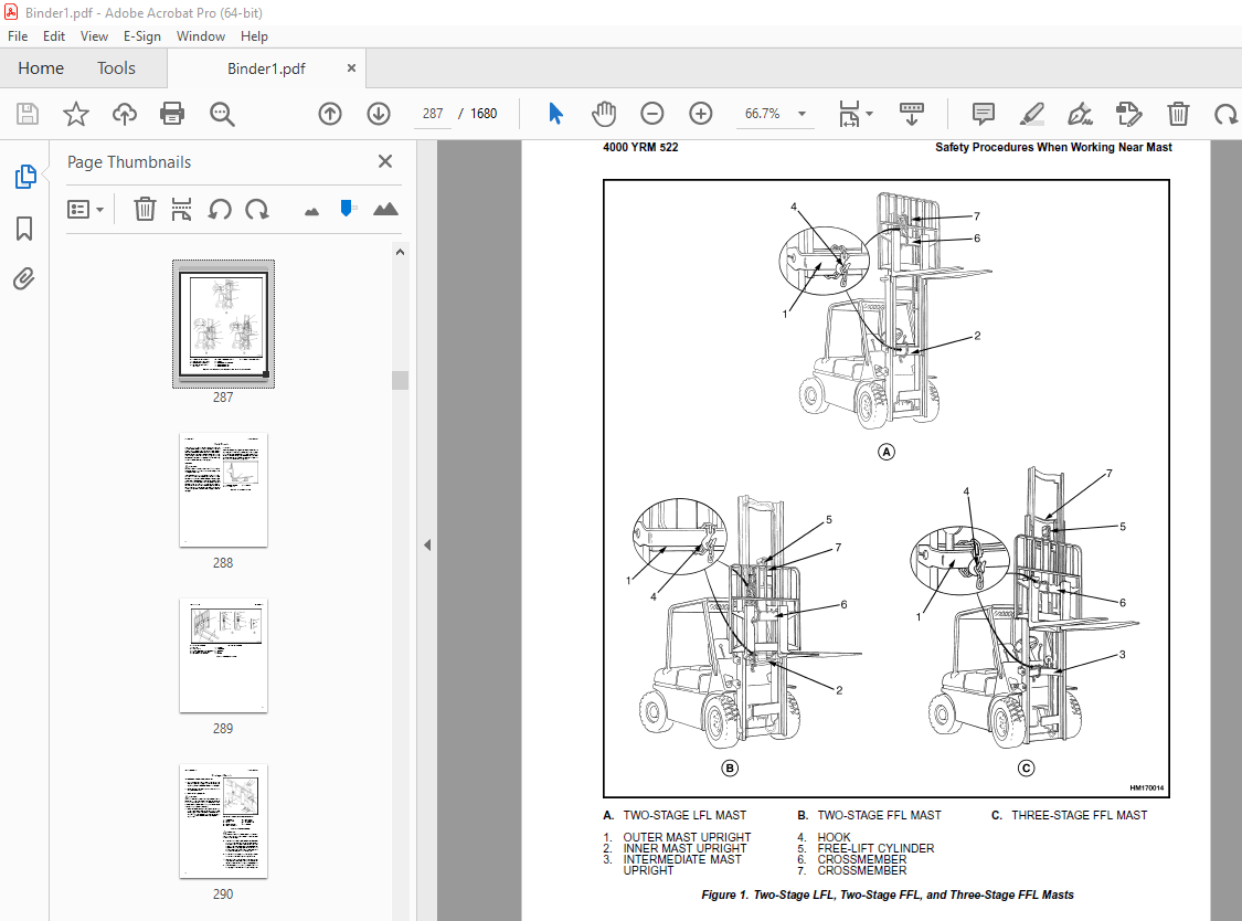
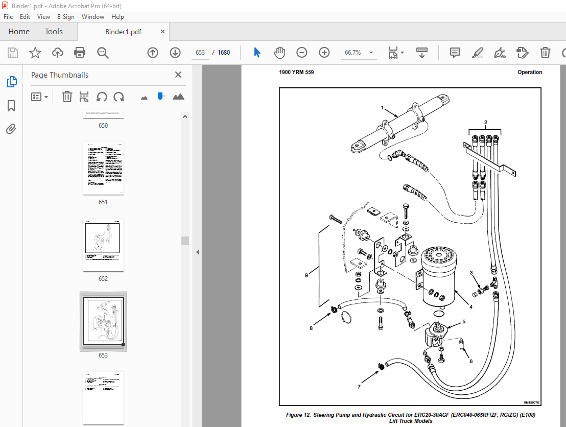
TABLE OF CONTENTS:
Yale Forklift D216 (ERP20-30ALF) Service Manual – PDF DOWNLOAD
524150790-2100YRM0103-(03-2007)-UK-EN (2) 1
toc 1
Tilt Cylinders 1
Safety Precautions Maintenance and Repair 2
General 5
Description 5
Tilt Cylinder Repair 5
Remove 5
Disassemble 5
Clean 5
Assemble 6
Tilt Cylinders With O-Ring or Single-Lip Seals 6
Tilt Cylinders 7
Install 8
Tilt Cylinder Leak Check 10
Tilt Cylinder Stroke and Mast Tilt Angle Adjustment 11
Torque Specifications 11
Piston Rod Nut 11
Retainer 11
Troubleshooting 12
tables 1
Table 1 Movement Rates (Maximum) for Tilt Cylinders 10
524150790-2100YRM0103-(03-2007)-UK-EN 17
toc 17
Tilt Cylinders 17
Safety Precautions Maintenance and Repair 18
General 21
Description 21
Tilt Cylinder Repair 21
Remove 21
Disassemble 21
Clean 21
Assemble 22
Tilt Cylinders With O-Ring or Single-Lip Seals 22
Tilt Cylinders 23
Install 24
Tilt Cylinder Leak Check 26
Tilt Cylinder Stroke and Mast Tilt Angle Adjustment 27
Torque Specifications 27
Piston Rod Nut 27
Retainer 27
Troubleshooting 28
tables 17
Table 1 Movement Rates (Maximum) for Tilt Cylinders 26
524150797-8000YRM0231-(02-2023)-UK-EN 33
General 39
Threaded Fasteners 39
Nomenclature, Threads 39
Strength Identification 40
Cotter (Split) Pins 41
Fastener Torque Tables 46
Conversion Table 48
524150797-8000YRM0231-(03-2020)-UK-EN 55
General 59
Threaded Fasteners 59
Nomenclature, Threads 59
Strength Identification 60
Cotter (Split) Pins 61
Fastener Torque Tables 66
Conversion Table 68
524158039-0620YRM0294-(09-2016)-UK-EN 75
General 79
Brush and Commutator Inspection 80
Hydraulic Pump Motor and Traction Motor 80
Steering Pump Motor 83
Normal Commutator Surface 83
Commutator Problems 83
Brush Replacement 88
Stoning the Commutator 91
Motors Repair 92
Disassemble 93
Traction Motor and Hydraulic Pump Motor 93
Steering Pump Motor 94
Assemble 98
Traction Motor and Hydraulic Pump Motor 98
Steering Pump Motor 100
Brush Alignment, Traction and Hydraulic Motors 102
Tests for Damaged Field and Armature 103
Test for an Open Circuit in One Armature Winding 103
Test for Short Circuit in One Armature Winding 103
Test for Short Circuit to Armature Shaft 104
Test for Open Circuit in Field Coil 104
Test for Short Circuit in Field Coil 105
Test for Short Circuit Between Field and Motor Case 105
Brush Holder Test 105
Troubleshooting 106
524158040-2240YRM0001-(01-2023)-UK-EN 111
General 117
Battery Type 117
Lead-Acid Batteries 117
Lithium-Ion Batteries 118
Specific Gravity 118
Chemical Reaction in a Cell 118
Electrical Terms 120
Battery Selection 121
Battery Voltage 122
Battery as a Counterweight 122
Battery Ratings 122
Kilowatt-Hours 122
Battery Maintenance 123
Safety Procedures 123
Maintenance Records 123
New Battery 123
Cleaning Battery 124
Adding Water to Battery 126
Hydrometer 126
Battery Temperature 127
Charging Battery 128
Types of Battery Charges 129
Methods of Charging 130
Troubleshooting Charger 131
Knowing When Battery Is Fully Charged 131
Where to Charge Batteries 131
Equipment Needed 131
Battery Connectors 132
Battery Care 132
Troubleshooting 134
524158040-2240YRM0001-(03-2020)-UK-EN 139
General 143
Battery Type 143
Lead-Acid Batteries 143
Lithium-Ion Batteries 144
Specific Gravity 144
Chemical Reaction in a Cell 144
Electrical Terms 146
Battery Selection 146
Battery Voltage 147
Battery as a Counterweight 148
Battery Ratings 148
Kilowatt-Hours 148
Battery Maintenance 148
Safety Procedures 148
Maintenance Records 149
New Battery 149
Cleaning Battery 149
Adding Water to Battery 151
Hydrometer 152
Battery Temperature 153
Charging Battery 154
Types of Battery Charges 154
Methods of Charging 156
Troubleshooting Charger 156
Knowing When Battery Is Fully Charged 157
Where to Charge Batteries 157
Equipment Needed 157
Battery Connectors 158
Battery Care 158
Troubleshooting 160
524158752-1600YRM0316-(08-2006)-UK-EN (2) 165
toc 165
Steering Axle 165
Safety Precautions Maintenance and Repair 166
General 169
Description 169
Steering Axle Assembly Repair 170
Remove 170
Install 170
Wheels and Hubs Repair 171
Remove and Disassemble 171
Clean 171
Assemble and Install 171
Spindles, Bearings, and Tie Rods Repair 173
Remove 173
Install 173
Steering Cylinder Repair 174
Remove and Disassemble 174
Clean and Inspect 175
Assemble and Install 175
Torque Specifications 175
Troubleshooting 176
524158752-1600YRM0316-(08-2006)-UK-EN 181
toc 181
Steering Axle 181
Safety Precautions Maintenance and Repair 182
General 185
Description 185
Steering Axle Assembly Repair 186
Remove 186
Install 186
Wheels and Hubs Repair 187
Remove and Disassemble 187
Clean 187
Assemble and Install 187
Spindles, Bearings, and Tie Rods Repair 189
Remove 189
Install 189
Steering Cylinder Repair 190
Remove and Disassemble 190
Clean and Inspect 191
Assemble and Install 191
Torque Specifications 191
Troubleshooting 192
524158753-1600YRM0720-(11-2006)-UK-EN (2) 197
toc 197
Steering Housing and Control Unit 197
Safety Precautions Maintenance and Repair 198
General 201
Description 201
Operation 202
Steering Wheel and Column Assembly Repair 203
Assembly Components, Remove 203
Steering Control Unit, Disassemble 208
Steering Control Unit, Clean 208
Steering Control Unit, Assemble 208
Assembly Components, Install 210
System Air Removal 212
Troubleshooting 212
524158753-1600YRM0720-(11-2006)-UK-EN 217
toc 217
Steering Housing and Control Unit 217
Safety Precautions Maintenance and Repair 218
General 221
Description 221
Operation 222
Steering Wheel and Column Assembly Repair 223
Assembly Components, Remove 223
Steering Control Unit, Disassemble 228
Steering Control Unit, Clean 228
Steering Control Unit, Assemble 228
Assembly Components, Install 230
System Air Removal 232
Troubleshooting 232
524158890-4000YRM0521-(03-2006)-UK-EN (2) 237
toc 237
Mast 237
Safety Precautions Maintenance and Repair 238
General 241
Description and Operation 241
Carriages 241
Mast Mounts 243
Two-Stage Mast, Limited Free-Lift (LFL) 244
Description and Operation 244
Two-Stage Mast, Full Free-Lift (FFL) 246
Description and Operation 246
Three-Stage Mast, Full Free-Lift (FFL) 248
Description and Operation 248
Four-Stage Mast 250
Description and Operation 250
Cylinder Cushion During Lifting Sequence 254
Cylinder Cushion During Lowering Sequence 255
524158890-4000YRM0521-(03-2006)-UK-EN 259
toc 259
Mast 259
Safety Precautions Maintenance and Repair 260
General 263
Description and Operation 263
Carriages 263
Mast Mounts 265
Two-Stage Mast, Limited Free-Lift (LFL) 266
Description and Operation 266
Two-Stage Mast, Full Free-Lift (FFL) 268
Description and Operation 268
Three-Stage Mast, Full Free-Lift (FFL) 270
Description and Operation 270
Four-Stage Mast 272
Description and Operation 272
Cylinder Cushion During Lifting Sequence 276
Cylinder Cushion During Lowering Sequence 277
524158891-4000YRM0522-(07-2010)-UK-EN (2) 281
toc 281
Mast 281
Safety Precautions Maintenance and Repair 282
General 285
Safety Procedures When Working Near Mast 286
Fork Repair 288
Remove 288
Install 288
Carriages Repair 290
Standard Carriage, Remove 290
Hang-On Sideshift Carriage, Remove 291
Standard Carriage and Hang-On Sideshift Carriage, Repair 292
Standard Carriage, Install 293
Hang-On Sideshift Carriage, Install 294
Integral Sideshift Carriage 294
Remove 294
Clean and Inspect 298
Repair 299
Install 300
Mast Repair 301
Remove 301
Two-Stage LFL and Two-Stage FFL Masts, Disassemble 303
Three-Stage FFL Mast 311
Disassemble 311
Mast and Chains, Clean and Inspect 314
Two-Stage LFL and Two-Stage FFL Mast, Assemble 315
Three-Stage FFL Mast, Assemble 316
Install 317
Lift Cylinders Repair 319
Main Lift Cylinders, Remove 319
Free-Lift Cylinder, Remove 319
Cylinders, Disassemble 320
Two-Stage Full Free-Lift Mast, Right-Hand Main Lift Cylinder 320
Two-Stage Full Free-Lift Mast, Left-Hand Main Lift Cylinder 322
Two-Stage Limited Free-Lift Mast and Three-Stage Full Free-Lift 322
Two-Stage Limited Free-Lift Mast and Three-Stage Full Free-Lift 323
Two-Stage Full Free-Lift Mast and Three-Stage Full Free-Lift Mas 324
Clean and Inspect 325
Cylinders, Assemble 325
Two-Stage Full Free-Lift Mast, Right-Hand Main Lift Cylinder 325
Two-Stage Full Free-Lift Mast, Left-Hand Main Lift Cylinder 326
Two-Stage Limited Free-Lift Mast and Three-Stage Full Free-Lift 327
Two-Stage Limited Free-Lift Mast and Three-Stage Full Free-Lift 327
Two-Stage Full Free-Lift Mast and Three-Stage Full Free-Lift Mas 328
Main Lift Cylinders, Install 329
Free-Lift Cylinder, Install 329
Header Hose Arrangements 330
Two-Stage LFL Mast, New Hose Install 330
Two-Stage LFL Mast, Adjust Hoses After Installation 335
Two-Stage FFL Mast, New Hose Install 335
Two-Stage FFL Mast, Adjust Hoses After Installation 343
Three-Stage FFL Mast, New Hose Install 343
Three-Stage FFL Mast, Adjust Hoses After Installation 354
Header Hose Arrangement 355
Two-Stage LFL Mast, New Hose Install 355
Two-Stage LFL Mast, Adjust Hoses After Installation 360
Two-Stage FFL Mast, New Hose Install 360
Two-Stage FFL Mast, Adjust Hoses After Installation 366
Three-Stage FFL Mast, New Hose Install 366
Three-Stage FFL Mast, Adjust Hoses After Install 375
Lift and Tilt System Leak Check 376
Lift Cylinders Leak Check 376
Tilt Cylinders Leak Check 376
Tilt Cylinders Adjustment 377
Lift Chains Adjustment 379
Mast Adjustment 381
Carriage Adjustment 383
Troubleshooting 384
tables 281
Table 1 Hook-Type Carriage Chain Adjustment 379
Table 2 Pin-Type Carriage Chain Adjustment 380
524158891-4000YRM0522-(07-2010)-UK-EN 387
toc 387
Mast 387
Safety Precautions Maintenance and Repair 388
General 391
Safety Procedures When Working Near Mast 392
Fork Repair 394
Remove 394
Install 394
Carriages Repair 396
Standard Carriage, Remove 396
Hang-On Sideshift Carriage, Remove 397
Standard Carriage and Hang-On Sideshift Carriage, Repair 398
Standard Carriage, Install 399
Hang-On Sideshift Carriage, Install 400
Integral Sideshift Carriage 400
Remove 400
Clean and Inspect 404
Repair 405
Install 406
Mast Repair 407
Remove 407
Two-Stage LFL and Two-Stage FFL Masts, Disassemble 409
Three-Stage FFL Mast 417
Disassemble 417
Mast and Chains, Clean and Inspect 420
Two-Stage LFL and Two-Stage FFL Mast, Assemble 421
Three-Stage FFL Mast, Assemble 422
Install 423
Lift Cylinders Repair 425
Main Lift Cylinders, Remove 425
Free-Lift Cylinder, Remove 425
Cylinders, Disassemble 426
Two-Stage Full Free-Lift Mast, Right-Hand Main Lift Cylinder 426
Two-Stage Full Free-Lift Mast, Left-Hand Main Lift Cylinder 428
Two-Stage Limited Free-Lift Mast and Three-Stage Full Free-Lift 428
Two-Stage Limited Free-Lift Mast and Three-Stage Full Free-Lift 429
Two-Stage Full Free-Lift Mast and Three-Stage Full Free-Lift Mas 430
Clean and Inspect 431
Cylinders, Assemble 431
Two-Stage Full Free-Lift Mast, Right-Hand Main Lift Cylinder 431
Two-Stage Full Free-Lift Mast, Left-Hand Main Lift Cylinder 432
Two-Stage Limited Free-Lift Mast and Three-Stage Full Free-Lift 433
Two-Stage Limited Free-Lift Mast and Three-Stage Full Free-Lift 433
Two-Stage Full Free-Lift Mast and Three-Stage Full Free-Lift Mas 434
Main Lift Cylinders, Install 435
Free-Lift Cylinder, Install 435
Header Hose Arrangements 436
Two-Stage LFL Mast, New Hose Install 436
Two-Stage LFL Mast, Adjust Hoses After Installation 441
Two-Stage FFL Mast, New Hose Install 441
Two-Stage FFL Mast, Adjust Hoses After Installation 449
Three-Stage FFL Mast, New Hose Install 449
Three-Stage FFL Mast, Adjust Hoses After Installation 460
Header Hose Arrangement 461
Two-Stage LFL Mast, New Hose Install 461
Two-Stage LFL Mast, Adjust Hoses After Installation 466
Two-Stage FFL Mast, New Hose Install 466
Two-Stage FFL Mast, Adjust Hoses After Installation 472
Three-Stage FFL Mast, New Hose Install 472
Three-Stage FFL Mast, Adjust Hoses After Install 481
Lift and Tilt System Leak Check 482
Lift Cylinders Leak Check 482
Tilt Cylinders Leak Check 482
Tilt Cylinders Adjustment 483
Lift Chains Adjustment 485
Mast Adjustment 487
Carriage Adjustment 489
Troubleshooting 490
tables 387
Table 1 Hook-Type Carriage Chain Adjustment 485
Table 2 Pin-Type Carriage Chain Adjustment 486
524179935-0100YRM0582-(07-2005)-UK-EN (2) 493
toc 493
Frame 493
Safety Precautions Maintenance and Repair 494
General 497
Description 497
Main Frame 497
Other Frame Weldments 497
Overhead Guard 500
Battery and Operator Restraint, Hood, and Seat Assembly 505
Battery Restraint 505
Hood 506
Operator Restraint System and Seat Assembly 507
Overhead Guard Replacement 507
Remove 507
Install 507
Hood, Seat Assembly and Operator Restraint Replacement 511
Hood and Seat Assembly 511
Remove 511
Install 513
Operator Restraint System 515
Counterweight Replacement 515
Remove 515
Install, Early Model ERP20-30ALF (B216) Lift Trucks 517
Install, Later Model ERP20-30ALF (B216) Trucks and ERP20-30ALF ( 517
Traction Motor Replacement 518
Remove 518
Install 520
Hydraulic Tank Repair 520
Remove 520
Inspect 521
Clean 521
Steam Method 522
Chemical Solution Method 522
Additional Preparations for Tank Repair 522
Small Leaks, Repair 523
Large Leaks, Repair 523
Preparations for Usage After Repair 523
Install 523
Painting Instructions 523
Safety Label Replacement 525
Battery Specifications 527
Early and Later ERP20-30ALF (B216) Model Trucks 527
ERP20-30ALF (ERP040-060DH) (D216) Model Trucks 527
tables 493
Table 1 Counterweights 516
524179935-0100YRM0582-(07-2005)-UK-EN 531
toc 531
Frame 531
Safety Precautions Maintenance and Repair 532
General 535
Description 535
Main Frame 535
Other Frame Weldments 535
Overhead Guard 538
Battery and Operator Restraint, Hood, and Seat Assembly 543
Battery Restraint 543
Hood 544
Operator Restraint System and Seat Assembly 545
Overhead Guard Replacement 545
Remove 545
Install 545
Hood, Seat Assembly and Operator Restraint Replacement 549
Hood and Seat Assembly 549
Remove 549
Install 551
Operator Restraint System 553
Counterweight Replacement 553
Remove 553
Install, Early Model ERP20-30ALF (B216) Lift Trucks 555
Install, Later Model ERP20-30ALF (B216) Trucks and ERP20-30ALF ( 555
Traction Motor Replacement 556
Remove 556
Install 558
Hydraulic Tank Repair 558
Remove 558
Inspect 559
Clean 559
Steam Method 560
Chemical Solution Method 560
Additional Preparations for Tank Repair 560
Small Leaks, Repair 561
Large Leaks, Repair 561
Preparations for Usage After Repair 561
Install 561
Painting Instructions 561
Safety Label Replacement 563
Battery Specifications 565
Early and Later ERP20-30ALF (B216) Model Trucks 565
ERP20-30ALF (ERP040-060DH) (D216) Model Trucks 565
tables 531
Table 1 Counterweights 554
524179938-1400YRM0575-(03-2003)-UK-EN (2) 569
toc 569
Drive Axle, Speed Reducer, and Differential 569
Safety Precautions Maintenance and Repair 570
General 573
Description 573
Drive Axle, Speed Reducer, and Differential Repair 574
Remove 574
Disassemble 576
Clean 578
Inspect 579
Assemble 579
Install 582
Torque Specifications 583
Troubleshooting 584
524179938-1400YRM0575-(03-2003)-UK-EN 587
toc 587
Drive Axle, Speed Reducer, and Differential 587
Safety Precautions Maintenance and Repair 588
General 591
Description 591
Drive Axle, Speed Reducer, and Differential Repair 592
Remove 592
Disassemble 594
Clean 596
Inspect 597
Assemble 597
Install 600
Torque Specifications 601
Troubleshooting 602
524179943-1800YRM0566-(03-2003)-UK-EN 605
toc 605
Brake System 605
Safety Precautions Maintenance and Repair 606
General 609
Description and Operation 609
Service Brakes 609
Master Cylinder 609
Parking Brake 610
Service Brake Repairs 611
Remove and Disassemble 611
Clean 613
Inspect 614
Assemble and Install 614
Adjust 615
Parking Brake Repair 619
Remove and Disassemble 619
Assemble and Install 619
Adjust 619
Master Cylinder Repair 621
Remove 621
Clean and Inspect 622
Repair 622
Install 624
Service Brakes Adjustment 625
Brake Pedal Adjustment 625
Master Cylinder Adjustment 625
Brake System Air Removal 625
Parking Brake Not Applied Switch Test 626
Torque Specifications 626
Troubleshooting 626
524179945-1900YRM0559-(04-2009)-UK-EN (2) 633
toc 633
Hydraulic System 633
Safety Precautions Maintenance and Repair 634
General 637
Description 637
Hydraulic System 637
Operation 645
Hydraulic System 645
Hydraulic Gear Pump 651
Steering Pump 651
Hydraulic Tank Repair 659
Tank, Remove [ERC/P16-20AAF (ERC030-040AF, AG/BG) (A814); ERC/P1 659
Tank, Remove [ERP20-30ALF (B216) and ERP20-30ALF (ERP040-060DH) 661
Tank, Remove [ERP20-32ALF (ERP040-065DH) (E216)] 662
Hydraulic Tank [ERC35-55HG (ERC70-120HH) (B839/C839)] 662
Inspect 663
Small Leaks, Repair 664
Large Leaks, Repair 664
Clean 664
Steam Method 664
Chemical Solution Method 665
Additional Methods for Tank Repair 665
Tank, Install [ERC/P16-20AAF (ERC030-040AF, AG/BG) (A814); ERC/P 665
Tank, Install [ERP20-30ALF (B216) and ERP20-30ALF (ERP040-060DH) 666
Tank, Install [ERP20-32ALF (ERP040-065DH) (E216)] 666
Filter Replacement 667
All Lift Trucks Except [ERC35-55HG (ERC70-120HH) (B839/C839); ER 667
Remove 667
Install 668
Lift Truck Models [ERC35-55HG (ERC70-120HH) (B839/C839)] 668
Remove 668
Install 668
Lift truck Models [ERC20-32AGF (ERC040-065GH) (A908) and ERC/P16 669
Remove 669
Install 669
Lift Truck Models [ERP20-32ALF (ERP040-065DH) (E216)] 671
Remove 671
Install 671
Hydraulic Pump Repair 674
Hydraulic Pump, Remove [ERC/P16-20AAF (ERC030-040AF, AG/BG) (A81 674
Hydraulic Pump, Disassemble ERC/P16-20AAF (ERC030-040AF, AG/BG) 674
Inspect 676
Clean 676
Pump Seal Replace and Pump Assemble 676
Assemble Pump on Motor 676
Hydraulic Pump and Motor, Install [ERC/P16-20AAF (ERC030-040AF, 678
Hydraulic Pump, Remove [ERP20-30ALF (B216); ERP20-30ALF (ERP040- 679
Hydraulic Pump, Disassemble [ERC35-55HG (ERC70-120HH) (B839/C839 680
Hydraulic Pump, Inspect [ERC35-55HG (ERC70-120HH) (B839/C839) an 682
Hydraulic Pump, Clean [ERC35-55HG (ERC70-120HH) (B839/C839) and 682
Hydraulic Pump, Assemble [ERC35-55HG (ERC70-120HH) (B839/C839) a 682
Hydraulic Pump and Motor, Install [ERP20-30ALF (B216); ERP20-30A 682
Main Control Valve Repair 684
Steering Pump Repair 684
Pump, Remove and Disassemble [ERC/P16-20AAF (ERC030-040AF, ERC03 684
Pump, Remove and Disassemble [ERP20-30ALF (B216); ERP20-30ALF (E 686
Pump, Assemble and Install 688
Steering Control Unit Replacement 689
Remove 689
Install 689
Steering Cylinder Repair 695
Main Control Valve Check and Adjust 695
Steering Relief Valve Check and Adjust 696
Specifications 696
Relief Valve Pressures* 696
Hydraulic Tank Capacity (dipstick full mark) 697
Hydraulic Pump Capacities – All Models Except ERC35-55HG (ERC70- 697
Hydraulic Pump Capacities – Models ERC35-55HG (ERC70-120HH) (B83 697
Troubleshooting 697
Steering 697
Steering Housing and Steering Control Unit 698
Hydraulic System 699
524179945-1900YRM0559-(04-2009)-UK-EN 705
toc 705
Hydraulic System 705
Safety Precautions Maintenance and Repair 706
General 709
Description 709
Hydraulic System 709
Operation 717
Hydraulic System 717
Hydraulic Gear Pump 723
Steering Pump 723
Hydraulic Tank Repair 731
Tank, Remove [ERC/P16-20AAF (ERC030-040AF, AG/BG) (A814); ERC/P1 731
Tank, Remove [ERP20-30ALF (B216) and ERP20-30ALF (ERP040-060DH) 733
Tank, Remove [ERP20-32ALF (ERP040-065DH) (E216)] 734
Hydraulic Tank [ERC35-55HG (ERC70-120HH) (B839/C839)] 734
Inspect 735
Small Leaks, Repair 736
Large Leaks, Repair 736
Clean 736
Steam Method 736
Chemical Solution Method 737
Additional Methods for Tank Repair 737
Tank, Install [ERC/P16-20AAF (ERC030-040AF, AG/BG) (A814); ERC/P 737
Tank, Install [ERP20-30ALF (B216) and ERP20-30ALF (ERP040-060DH) 738
Tank, Install [ERP20-32ALF (ERP040-065DH) (E216)] 738
Filter Replacement 739
All Lift Trucks Except [ERC35-55HG (ERC70-120HH) (B839/C839); ER 739
Remove 739
Install 740
Lift Truck Models [ERC35-55HG (ERC70-120HH) (B839/C839)] 740
Remove 740
Install 740
Lift truck Models [ERC20-32AGF (ERC040-065GH) (A908) and ERC/P16 741
Remove 741
Install 741
Lift Truck Models [ERP20-32ALF (ERP040-065DH) (E216)] 743
Remove 743
Install 743
Hydraulic Pump Repair 746
Hydraulic Pump, Remove [ERC/P16-20AAF (ERC030-040AF, AG/BG) (A81 746
Hydraulic Pump, Disassemble ERC/P16-20AAF (ERC030-040AF, AG/BG) 746
Inspect 748
Clean 748
Pump Seal Replace and Pump Assemble 748
Assemble Pump on Motor 748
Hydraulic Pump and Motor, Install [ERC/P16-20AAF (ERC030-040AF, 750
Hydraulic Pump, Remove [ERP20-30ALF (B216); ERP20-30ALF (ERP040- 751
Hydraulic Pump, Disassemble [ERC35-55HG (ERC70-120HH) (B839/C839 752
Hydraulic Pump, Inspect [ERC35-55HG (ERC70-120HH) (B839/C839) an 754
Hydraulic Pump, Clean [ERC35-55HG (ERC70-120HH) (B839/C839) and 754
Hydraulic Pump, Assemble [ERC35-55HG (ERC70-120HH) (B839/C839) a 754
Hydraulic Pump and Motor, Install [ERP20-30ALF (B216); ERP20-30A 754
Main Control Valve Repair 756
Steering Pump Repair 756
Pump, Remove and Disassemble [ERC/P16-20AAF (ERC030-040AF, ERC03 756
Pump, Remove and Disassemble [ERP20-30ALF (B216); ERP20-30ALF (E 758
Pump, Assemble and Install 760
Steering Control Unit Replacement 761
Remove 761
Install 761
Steering Cylinder Repair 767
Main Control Valve Check and Adjust 767
Steering Relief Valve Check and Adjust 768
Specifications 768
Relief Valve Pressures* 768
Hydraulic Tank Capacity (dipstick full mark) 769
Hydraulic Pump Capacities – All Models Except ERC35-55HG (ERC70- 769
Hydraulic Pump Capacities – Models ERC35-55HG (ERC70-120HH) (B83 769
Troubleshooting 769
Steering 769
Steering Housing and Steering Control Unit 770
Hydraulic System 771
524179946-2000YRM0562-(02-2009)-UK-EN (2) 777
toc 777
Manual hydraulic Control Valve 777
Safety Precautions Maintenance and Repair 778
General 781
Description 781
Operation 784
ERC/P16-20AAF (ERC030-040AF, AG/BG) (A814); ERC/P16-20AAF (ERC03 784
ERP20-30ALF (B216), ERP20-30ALF (ERP040-060DH) (D216) and ERP20- 784
Lift Section 786
Tilt Section 786
Tilt Backward 786
Tilt Forward 786
Relief Valve 788
Main Control Valve Repair 789
Main Control Valve Without OPS Solenoid 789
Remove 789
Disassemble 789
Clean and Inspect 793
Assemble 793
Install [ERC/P16-20AAF (ERC030-040AF, AG/BG) (A814); ERC/P16-20A 794
Install [ERP20-30ALF (B216), ERP20-30ALF (ERP040-060DH) (D216) a 794
Main Control Valve With OPS Solenoid 795
Remove 795
Disassemble 795
Clean and Inspect 797
Relief Valve Repair 799
Assemble 800
Install 801
Control Lever Linkage Repair 801
Remove [ERC/P16-20AAF (ERC030-040AF, AG/BG) (A814),ERC/P16-20AAF 801
Disassemble [ERC/P16-20AAF (ERC030-040AF, AG/BG) (A814),ERC/P16- 801
Assemble and Install [ERC/P16-20AAF (ERC030-040AF, AG/BG) (A814) 803
Control Valve Linkage Repair 803
Remove and Disassemble [ERC/P16-20AAF (ERC030-040AF, AG/BG) (A81 803
Assemble and Install [ERC/P16-20AAF (ERC030-040AF, AG/BG) (A814) 804
Control Lever Linkage Repair 804
Remove [ERP20-30ALF (B216), ERP20-30ALF (ERP040-060DH) (D216) an 804
Disassemble [ERP20-30ALF (B216), ERP20-30ALF (ERP040-060DH) (D21 806
Assemble and Install [ERP20-30ALF (B216), ERP20-30ALF (ERP040-06 806
Pressure Relief Valve Check and Adjustment 807
Primary Relief Valve 807
Secondary Relief Valve 808
Troubleshooting 809
524179946-2000YRM0562-(02-2009)-UK-EN 813
toc 813
Manual hydraulic Control Valve 813
Safety Precautions Maintenance and Repair 814
General 817
Description 817
Operation 820
ERC/P16-20AAF (ERC030-040AF, AG/BG) (A814); ERC/P16-20AAF (ERC03 820
ERP20-30ALF (B216), ERP20-30ALF (ERP040-060DH) (D216) and ERP20- 820
Lift Section 822
Tilt Section 822
Tilt Backward 822
Tilt Forward 822
Relief Valve 824
Main Control Valve Repair 825
Main Control Valve Without OPS Solenoid 825
Remove 825
Disassemble 825
Clean and Inspect 829
Assemble 829
Install [ERC/P16-20AAF (ERC030-040AF, AG/BG) (A814); ERC/P16-20A 830
Install [ERP20-30ALF (B216), ERP20-30ALF (ERP040-060DH) (D216) a 830
Main Control Valve With OPS Solenoid 831
Remove 831
Disassemble 831
Clean and Inspect 833
Relief Valve Repair 835
Assemble 836
Install 837
Control Lever Linkage Repair 837
Remove [ERC/P16-20AAF (ERC030-040AF, AG/BG) (A814),ERC/P16-20AAF 837
Disassemble [ERC/P16-20AAF (ERC030-040AF, AG/BG) (A814),ERC/P16- 837
Assemble and Install [ERC/P16-20AAF (ERC030-040AF, AG/BG) (A814) 839
Control Valve Linkage Repair 839
Remove and Disassemble [ERC/P16-20AAF (ERC030-040AF, AG/BG) (A81 839
Assemble and Install [ERC/P16-20AAF (ERC030-040AF, AG/BG) (A814) 840
Control Lever Linkage Repair 840
Remove [ERP20-30ALF (B216), ERP20-30ALF (ERP040-060DH) (D216) an 840
Disassemble [ERP20-30ALF (B216), ERP20-30ALF (ERP040-060DH) (D21 842
Assemble and Install [ERP20-30ALF (B216), ERP20-30ALF (ERP040-06 842
Pressure Relief Valve Check and Adjustment 843
Primary Relief Valve 843
Secondary Relief Valve 844
Troubleshooting 845
524183080-0620YRM1053-(03-2010)-UK-EN (2) 849
toc 849
AC Motor Repair 849
Safety Precautions Maintenance and Repair 850
General 853
AC Motor Repair 854
Disassemble 854
Assemble 856
Drive End Bearing, Replace 857
Disassemble, ERP20-32ALF (ERP040-065DH) (E216) Traction Motor 857
Assemble, ERP20-32ALF (ERP040-065DH) (E216) Traction Motor 859
Troubleshooting 860
524183080-0620YRM1053-(03-2010)-UK-EN 863
toc 863
AC Motor Repair 863
Safety Precautions Maintenance and Repair 864
General 867
AC Motor Repair 868
Disassemble 868
Assemble 870
Drive End Bearing, Replace 871
Disassemble, ERP20-32ALF (ERP040-065DH) (E216) Traction Motor 871
Assemble, ERP20-32ALF (ERP040-065DH) (E216) Traction Motor 873
Troubleshooting 874
524183081-1600YRM1054-(11-2006)-UK-EN (2) 877
toc 877
Steering System for AC Electric Lift Trucks 877
Safety Precautions Maintenance and Repair 878
General 881
Description 882
Steering Wheel and Column Assembly Repair 883
General 883
Assembly Components, Remove 885
Assembly Components, Install 886
Power Steering Motor and Pump 887
Description 887
Remove 887
Disassemble 890
Install 890
Power Steering Pump, Repair 890
Seal, Replace 891
Steering System Air Removal 892
Steering Pressure Check 892
Steering Motor Circuits Check 893
Troubleshooting 894
524183081-1600YRM1054-(11-2006)-UK-EN 899
toc 899
Steering System for AC Electric Lift Trucks 899
Safety Precautions Maintenance and Repair 900
General 903
Description 904
Steering Wheel and Column Assembly Repair 905
General 905
Assembly Components, Remove 907
Assembly Components, Install 908
Power Steering Motor and Pump 909
Description 909
Remove 909
Disassemble 912
Install 912
Power Steering Pump, Repair 912
Seal, Replace 913
Steering System Air Removal 914
Steering Pressure Check 914
Steering Motor Circuits Check 915
Troubleshooting 916
524183082-2200YRM1055-(10-2009)-UK-EN (2) 921
toc 921
Electrical System (Trucks With AC Controllers) 921
Safety Precautions Maintenance and Repair 922
General 925
Description 926
Features of the Display Panels 926
Other Control Components 927
Display Panel and Key Switch Replacement 928
Display Panel, Replace 928
Key Switch, Replace 930
Controller Replacement 930
Traction and Pump Motor Controller Replacement 930
Master Controller, Replace 936
Master Controller, Remove ERP20-30ALF (ERP040-060DH) (D216), ERP 936
Master Controller, Install ERP20-30ALF (ERP040-060DH) (D216), ER 936
Master Controller, Remove ERC/P16-20AAF (ERC030-040AH) (B814/C81 938
Master Controller, Install ERC/P16-20AAF (ERC030-040AH) (B814/C8 938
Master Controller, Remove ERC35-55HG (ERC070-120HH) (B839/C839) 940
Master Controller, Install ERC35-55HG (ERC070-120HH) (B839/C839) 940
Control Components Replacement 941
General 941
Start Switch, Replace 941
Brake Light Switch, Replace 942
Seat Switch, Replace 942
Parking Brake Switch, Replace 943
Foot Directional Control Pedal Direction Switches, Replace 945
Steering Column Direction Control Switches, Replace 948
Remove 948
Install 948
Brake Fluid Switch, Replace 950
Brush Wear and Over Temperature Sensors (DC Pump Motor Only) 950
Rocker Switches for Lights, Replace 950
Accelerator Position Sensor, Replace 951
On-Demand Steering Sensor, Replace 952
Lights, Converter, Relay, and Reverse Alarm 952
Brake, Tail, and Reverse Light Assembly, Replace 953
Incandescent Assembly 953
LED Assembly – Remove 955
LED Assembly – Install 955
Strobe Light Assembly, Replace 958
Wire Harness Repair 959
Del-City Crimp-Solder-Shrink Splice 959
Front, Rear Driving Light or Spot Light Assemblies, Replace 960
Converter, Replace 960
Remove, Lift Truck Models ERP20-30ALF (ERP040-060DH) (D216), ERP 960
Install, Lift Truck Models ERP20-30ALF (ERP040-060DH) (D216), ER 962
Remove, Lift Truck Models ERC20-32AGF (ERC040-065GH) (A908) and 962
Install, Lift Truck Models ERC20-32AGF (ERC040-065GH) (A908) and 962
Remove, Lift Truck Models ERC35-55HG (ERC70-120HH) (B839/C839) 964
Install, Lift Truck Models ERC35-55HG (ERC70-120HH) (B839/C839) 964
Reverse Relay, Replace 965
Lift Truck Models ERC20-32AGF (ERC040-065GH) (A908), ERC/P16-20A 965
Lift Truck Models ERC35-55HG (ERC70-120HH) (B839/C839) 965
Backup Alarm, Replace 967
Horn and Horn Button, Replace 967
Horn Replacement for Lift Trucks ERP20-30ALF (ERP040-060DH) (D21 967
Horn Replacement for Lift Trucks ERC35-55HG (ERC70-120HH) (B839/ 969
Horn Switch and Cover, Replace 970
Hydraulic Pump Switches 971
Fan Power Supply, Replace 971
Remove, Lift Truck Models ERC35-55HG (ERC70-120HH) (B839/C839) 971
Install, Lift Truck Models ERC35-55HG (ERC70-120HH) (B839/C839) 971
Remove, Lift Truck Models ERP20-30ALF (ERP040-060DH) (D216) and 972
Install, Lift Truck Models ERP20-30ALF (ERP040-060DH) (D216) and 973
Remove, Lift Truck Models ERC20-32AGF (ERC040-065GH) (A908) 973
Install, Lift Truck Models ERC20-32AGF (ERC040-065GH) (A908) 973
Control and Power Fuse Check 974
Fuse Locations 974
Brake Light Switch Adjustment 980
Seat Switch Check 981
Seat Brake Adjustment 981
Parking Brake Switch Adjustment 982
Direction Switches Check 982
Foot Directional Control Pedal 982
Steering Column 983
Foot Directional Control Pedal or Accelerator Pedal Adjustment 983
Accelerator Position Sensor Adjustment and Start Switch Adjustme 984
Acceleration Position Sensor, Adjust 984
Start Switch, Adjust 986
tables 921
Table 1 Wire Splice Size 959
524183082-2200YRM1055-(10-2009)-UK-EN 989
toc 989
Electrical System (Trucks With AC Controllers) 989
Safety Precautions Maintenance and Repair 990
General 993
Description 994
Features of the Display Panels 994
Other Control Components 995
Display Panel and Key Switch Replacement 996
Display Panel, Replace 996
Key Switch, Replace 998
Controller Replacement 998
Traction and Pump Motor Controller Replacement 998
Master Controller, Replace 1004
Master Controller, Remove ERP20-30ALF (ERP040-060DH) (D216), ERP 1004
Master Controller, Install ERP20-30ALF (ERP040-060DH) (D216), ER 1004
Master Controller, Remove ERC/P16-20AAF (ERC030-040AH) (B814/C81 1006
Master Controller, Install ERC/P16-20AAF (ERC030-040AH) (B814/C8 1006
Master Controller, Remove ERC35-55HG (ERC070-120HH) (B839/C839) 1008
Master Controller, Install ERC35-55HG (ERC070-120HH) (B839/C839) 1008
Control Components Replacement 1009
General 1009
Start Switch, Replace 1009
Brake Light Switch, Replace 1010
Seat Switch, Replace 1010
Parking Brake Switch, Replace 1011
Foot Directional Control Pedal Direction Switches, Replace 1013
Steering Column Direction Control Switches, Replace 1016
Remove 1016
Install 1016
Brake Fluid Switch, Replace 1018
Brush Wear and Over Temperature Sensors (DC Pump Motor Only) 1018
Rocker Switches for Lights, Replace 1018
Accelerator Position Sensor, Replace 1019
On-Demand Steering Sensor, Replace 1020
Lights, Converter, Relay, and Reverse Alarm 1020
Brake, Tail, and Reverse Light Assembly, Replace 1021
Incandescent Assembly 1021
LED Assembly – Remove 1023
LED Assembly – Install 1023
Strobe Light Assembly, Replace 1026
Wire Harness Repair 1027
Del-City Crimp-Solder-Shrink Splice 1027
Front, Rear Driving Light or Spot Light Assemblies, Replace 1028
Converter, Replace 1028
Remove, Lift Truck Models ERP20-30ALF (ERP040-060DH) (D216), ERP 1028
Install, Lift Truck Models ERP20-30ALF (ERP040-060DH) (D216), ER 1030
Remove, Lift Truck Models ERC20-32AGF (ERC040-065GH) (A908) and 1030
Install, Lift Truck Models ERC20-32AGF (ERC040-065GH) (A908) and 1030
Remove, Lift Truck Models ERC35-55HG (ERC70-120HH) (B839/C839) 1032
Install, Lift Truck Models ERC35-55HG (ERC70-120HH) (B839/C839) 1032
Reverse Relay, Replace 1033
Lift Truck Models ERC20-32AGF (ERC040-065GH) (A908), ERC/P16-20A 1033
Lift Truck Models ERC35-55HG (ERC70-120HH) (B839/C839) 1033
Backup Alarm, Replace 1035
Horn and Horn Button, Replace 1035
Horn Replacement for Lift Trucks ERP20-30ALF (ERP040-060DH) (D21 1035
Horn Replacement for Lift Trucks ERC35-55HG (ERC70-120HH) (B839/ 1037
Horn Switch and Cover, Replace 1038
Hydraulic Pump Switches 1039
Fan Power Supply, Replace 1039
Remove, Lift Truck Models ERC35-55HG (ERC70-120HH) (B839/C839) 1039
Install, Lift Truck Models ERC35-55HG (ERC70-120HH) (B839/C839) 1039
Remove, Lift Truck Models ERP20-30ALF (ERP040-060DH) (D216) and 1040
Install, Lift Truck Models ERP20-30ALF (ERP040-060DH) (D216) and 1041
Remove, Lift Truck Models ERC20-32AGF (ERC040-065GH) (A908) 1041
Install, Lift Truck Models ERC20-32AGF (ERC040-065GH) (A908) 1041
Control and Power Fuse Check 1042
Fuse Locations 1042
Brake Light Switch Adjustment 1048
Seat Switch Check 1049
Seat Brake Adjustment 1049
Parking Brake Switch Adjustment 1050
Direction Switches Check 1050
Foot Directional Control Pedal 1050
Steering Column 1051
Foot Directional Control Pedal or Accelerator Pedal Adjustment 1051
Accelerator Position Sensor Adjustment and Start Switch Adjustme 1052
Acceleration Position Sensor, Adjust 1052
Start Switch, Adjust 1054
tables 989
Table 1 Wire Splice Size 1027
524183083-2200YRM1056-(03-2009)-UK-EN (2) 1057
toc 1057
AC Motor Controllers/Display Panel 1057
Safety Precautions Maintenance and Repair 1058
Description 1061
General 1061
AC Motors 1061
Motor Controllers 1061
Master Controller 1061
Dash Display 1061
Controller Area Network Bus (CANbus) 1061
Master Controller Checks and Adjustments 1062
Function Settings 1063
General 1063
Function Numbers 1063
Function Descriptions 1066
General 1066
Function Number 1 BATTERY VOLTAGE 1066
Function Number 2 EXTENDED SHIFT 1066
Function Number 3 ACCELERATION 1 1066
Function Number 4 ACCELERATION 2 1066
Function Number 5 TOP SPEED LIMIT 1066
Function Number 6 REGEN BRAKING 1066
Function Number 7 AUTO DECELERATION 1067
Function Number 8 BDI ADJUSTMENT 1067
Function Number 9 LIFT INTERRUPT 1067
Function Number 10 POWER STEERING TIME DELAY 1067
Function Number 11 SERVICE REMINDER 1067
Function Number 12 CUSTOM 1067
Function Number 13 PUMP SPEED 1 1067
Function Number 14 PUMP SPEED 2 1068
Function Number 15 PUMP SPEED 3 1068
Function Number 16 PUMP ACCELERATION 1068
Troubleshooting 1068
General 1068
Controller Status Light Emitting Diodes (LEDs) 1069
Master Controller 1069
AC Motor Controllers 1069
Status Codes 1075
AC Motor Controllers Status Code Charts 1077
Troubleshooting When Dash and/or Lift Truck is not Operational 1098
Typical Symptoms 1098
Truck Runs but Dash Display is not Operational, or Only Displays 1098
Truck Does Not Run and Dash is Not Operational or Only Displays 1099
Hydraulics Operate Normally, Traction Does Not Operate Correctly 1100
Traction Operates Normally, Hydraulics do Not Operate Correctly, 1100
AC Transistor Motor Controller Replacement 1100
General 1100
General Maintenance Instructions 1106
Special Precautions 1106
Fuses 1107
Fan Test 1107
Contactors 1107
Repair 1107
Thermal Sensors 1111
Motor Controller, Replace 1111
Display Panel 1112
General 1112
Premium Display Panel 1112
Standard Display Panel 1112
Display Functions and Features 1113
Key-On Initialization 1113
Standard Display 1114
Premium Display 1114
Lift Truck Inspection Function 1115
Access to Service Functions 1115
Service Functions 1115
Service Functions 1116
Performance Modes 1118
Battery Discharge Indicator (BDI) 1118
Hourmeter 1119
Dash Display Service Menu Navigation 1125
General 1125
Moving Through Menu Selections 1125
Editing and Adding Information 1125
tables 1057
Table 1 Factory Parameters for ERP20-30ALF (ERP040-060DH) (D216 1063
Table 2 Factory Setting for ERC020-032AGF (ERC40-65GH) (A908) 1064
Table 3 Factory Setting for ERC/P16-20AAF (ERC030-040AH) (B814/ 1064
Table 4 Factory Parameters for ERC35-55HG (ERC70-120HH) (B839/C 1065
Table 5 List of Status Codes 1075
Table 6 42-Pin Connections/Descriptions for Master Controller 1108
Table 7 Pin Connections/Descriptions for 72/80 (Gen IV) Volt Mo 1110
Table 8 Pin Connections/Descriptions for 36/48 and 72v/80v (Gen 1110
524183083-2200YRM1056-(03-2009)-UK-EN 1129
toc 1129
AC Motor Controllers/Display Panel 1129
Safety Precautions Maintenance and Repair 1130
Description 1133
General 1133
AC Motors 1133
Motor Controllers 1133
Master Controller 1133
Dash Display 1133
Controller Area Network Bus (CANbus) 1133
Master Controller Checks and Adjustments 1134
Function Settings 1135
General 1135
Function Numbers 1135
Function Descriptions 1138
General 1138
Function Number 1 BATTERY VOLTAGE 1138
Function Number 2 EXTENDED SHIFT 1138
Function Number 3 ACCELERATION 1 1138
Function Number 4 ACCELERATION 2 1138
Function Number 5 TOP SPEED LIMIT 1138
Function Number 6 REGEN BRAKING 1138
Function Number 7 AUTO DECELERATION 1139
Function Number 8 BDI ADJUSTMENT 1139
Function Number 9 LIFT INTERRUPT 1139
Function Number 10 POWER STEERING TIME DELAY 1139
Function Number 11 SERVICE REMINDER 1139
Function Number 12 CUSTOM 1139
Function Number 13 PUMP SPEED 1 1139
Function Number 14 PUMP SPEED 2 1140
Function Number 15 PUMP SPEED 3 1140
Function Number 16 PUMP ACCELERATION 1140
Troubleshooting 1140
General 1140
Controller Status Light Emitting Diodes (LEDs) 1141
Master Controller 1141
AC Motor Controllers 1141
Status Codes 1147
AC Motor Controllers Status Code Charts 1149
Troubleshooting When Dash and/or Lift Truck is not Operational 1170
Typical Symptoms 1170
Truck Runs but Dash Display is not Operational, or Only Displays 1170
Truck Does Not Run and Dash is Not Operational or Only Displays 1171
Hydraulics Operate Normally, Traction Does Not Operate Correctly 1172
Traction Operates Normally, Hydraulics do Not Operate Correctly, 1172
AC Transistor Motor Controller Replacement 1172
General 1172
General Maintenance Instructions 1178
Special Precautions 1178
Fuses 1179
Fan Test 1179
Contactors 1179
Repair 1179
Thermal Sensors 1183
Motor Controller, Replace 1183
Display Panel 1184
General 1184
Premium Display Panel 1184
Standard Display Panel 1184
Display Functions and Features 1185
Key-On Initialization 1185
Standard Display 1186
Premium Display 1186
Lift Truck Inspection Function 1187
Access to Service Functions 1187
Service Functions 1187
Service Functions 1188
Performance Modes 1190
Battery Discharge Indicator (BDI) 1190
Hourmeter 1191
Dash Display Service Menu Navigation 1197
General 1197
Moving Through Menu Selections 1197
Editing and Adding Information 1197
tables 1129
Table 1 Factory Parameters for ERP20-30ALF (ERP040-060DH) (D216 1135
Table 2 Factory Setting for ERC020-032AGF (ERC40-65GH) (A908) 1136
Table 3 Factory Setting for ERC/P16-20AAF (ERC030-040AH) (B814/ 1136
Table 4 Factory Parameters for ERC35-55HG (ERC70-120HH) (B839/C 1137
Table 5 List of Status Codes 1147
Table 6 42-Pin Connections/Descriptions for Master Controller 1180
Table 7 Pin Connections/Descriptions for 72/80 (Gen IV) Volt Mo 1182
Table 8 Pin Connections/Descriptions for 36/48 and 72v/80v (Gen 1182
524183085-2200YRM1058-(04-2011)-UK-EN (2) 1201
toc 1201
Troubleshooting and Adjustments Using the AC Controls Program (E 1201
Safety Precautions Maintenance and Repair 1202
General 1205
Computer Requirements 1205
Software, Install 1205
Language Selection 1205
Demo Mode 1206
Connect PC to Lift Truck 1210
Starting AC Controls Program 1212
Lift Truck Control Setup 1217
Change Lift Truck Serial Number or Hourmeter 1217
Setting Factory Default Values or Changing Lift Truck Parameters 1218
Create New Custom Lift Truck Configuration 1224
Lift Truck Configuration Properties 1227
Import New Lift Truck Configuration From Disk 1230
Delete Custom Lift Truck Configuration or Password File 1232
Dash Display 1235
Custom Display Languages 1235
Download Display Language 1237
Clear Operator Log 1237
Password Functions 1240
Enable/Disable Password and Lift Truck Inspection Functions 1240
Truck Inspection Checklist 1240
Password 1240
Password Properties 1240
Create New Password File 1245
Download Passwords 1246
Upload Passwords 1248
Reports Menu 1250
Devices Report 1250
Custom Report 1250
Password Report 1250
Operator Report 1257
Current Settings Report 1260
Status Code Report 1264
Status Codes Log 1267
Troubleshooting 1269
Diagnostics 1269
Help Menu 1272
General 1272
Contents 1272
Technical Support 1272
About Electric Truck AC Controls Program 1272
524183085-2200YRM1058-(04-2011)-UK-EN 1279
toc 1279
Troubleshooting and Adjustments Using the AC Controls Program (E 1279
Safety Precautions Maintenance and Repair 1280
General 1283
Computer Requirements 1283
Software, Install 1283
Language Selection 1283
Demo Mode 1284
Connect PC to Lift Truck 1288
Starting AC Controls Program 1290
Lift Truck Control Setup 1295
Change Lift Truck Serial Number or Hourmeter 1295
Setting Factory Default Values or Changing Lift Truck Parameters 1296
Create New Custom Lift Truck Configuration 1302
Lift Truck Configuration Properties 1305
Import New Lift Truck Configuration From Disk 1308
Delete Custom Lift Truck Configuration or Password File 1310
Dash Display 1313
Custom Display Languages 1313
Download Display Language 1315
Clear Operator Log 1315
Password Functions 1318
Enable/Disable Password and Lift Truck Inspection Functions 1318
Truck Inspection Checklist 1318
Password 1318
Password Properties 1318
Create New Password File 1323
Download Passwords 1324
Upload Passwords 1326
Reports Menu 1328
Devices Report 1328
Custom Report 1328
Password Report 1328
Operator Report 1335
Current Settings Report 1338
Status Code Report 1342
Status Codes Log 1345
Troubleshooting 1347
Diagnostics 1347
Help Menu 1350
General 1350
Contents 1350
Technical Support 1350
About Electric Truck AC Controls Program 1350
524183086-8000YRM1059-(08-2012)-UK-EN (2) 1357
toc 1357
Electrical Diagrams 1357
Safety Precautions Maintenance and Repair 1358
524183086-8000YRM1059-(08-2012)-UK-EN 1433
toc 1433
Electrical Diagrams 1433
Safety Precautions Maintenance and Repair 1434
524183087-8000YRM1060-(02-2010)-UK-EN (2) 1509
toc 1509
Periodic Maintenance 1509
Safety Precautions Maintenance and Repair 1510
General 1515
Serial Number Data 1515
How to Move Disabled Lift Truck 1515
How to Tow Lift Truck 1515
How to Put Lift Truck on Blocks 1516
How to Raise Drive Tires 1516
How to Raise Steering Tires 1516
How to Clean a Lift Truck 1516
Maintenance Schedule 1518
Maintenance Procedures Every 8 Hours or Daily 1525
How to Make Checks With Key OFF 1525
Tires and Wheels 1525
Forks 1526
Inspect 1526
Mast and Lift Chains, Inspect 1527
Safety Labels 1527
Steering Column Latch 1527
Operator Restraint System 1528
Automatic Locking Retractor (ALR) 1528
Emergency Locking Retractor (ELR) 1528
Battery Restraint System ERC20-32AGF (ERC040-065GH) (A908) and E 1529
Battery Restraint System ERP20-30ALF (ERP040-060DH) (D216) Lift 1530
Battery 1530
Attachment 1531
Hydraulic System 1531
How to Make Checks With Key ON 1532
Horn, Lights, and Alarm 1532
Steering System 1532
Service Brakes 1532
Parking Brake 1532
Control Levers and Pedals 1533
Direction and Speed Control Pedals 1533
Lift System Operation 1533
Oil Leaks 1533
First Service After First 100 Hours of Operation 1533
Change Filter for Hydraulic Oil 1533
Maintenance Procedures Every 250 Hours or 6 Weeks 1535
Steering King Pins ERC/P16-20AAF (B814/C814) Trucks Only 1535
Steering Tie Rods and Spindles 1535
Maintenance Procedures Every 500 Hours or 3 Months 1535
Differential and Speed Reducer ERC20-32AGF (ERC040-065GH) (A908) 1535
Wheel Nut Torques 1536
Header Hose Checks 1536
Mast Lubrication 1536
Forks 1540
Remove 1540
Inspect 1540
Install 1540
Adjust 1541
Brake Fluid ERC/P16-20AAF (ERC030-040AH) (B814/C814) and ERC20-3 1541
Parking Brake Adjustment 1541
Seat Brake Operations Check 1542
Maintenance Procedures Every 1000 Hours or 6 Months 1542
Lift Chains 1542
Wear Check 1542
Lift Chain Lubrication 1543
Forks 1543
Check Upper and Lower Bearings, Integral Sideshift Carriage 1543
Steering King Pins ERC20-32AGF (ERC040-065GH) (A908) Lift Truck 1544
Steering Tie Rods ERP20-30ALF (ERP040-060DH) (D216) Lift Truck M 1544
Steering Axle Spindles 1544
King Pins ERP20-30ALF (ERP040-060DH) (D216) 1544
Hydraulic Tank Breather 1544
ERP20-30ALF (ERP040-060DH) (D216) 1544
ERC20-32AGF (ERC040-065GH) (A908) 1545
ERC/P16-20AAF (ERC030-040AH) (B814/C814) 1545
Differential and Speed Reducer ERP20-30ALF (ERP040-060DH) (D216) 1545
Brake Fluid ERP20-30ALF (ERP040-060DH) (D216) Lift Truck Models 1546
Other Lubrication 1546
Electrical Inspection 1546
Contactors 1546
Motor Brushes (DC Pump) 1546
Motor Brushes, General 1546
Maintenance Procedures Every 2000 Hours or Yearly 1550
Hydraulic System 1550
Change Filter for Hydraulic Oil 1550
Change Hydraulic Oil 1551
Differential and Speed Reducer 1551
Brake Fluid Replacement 1552
Service Brakes 1552
Steering Tie Rods and Spindle Lift Truck Models ERC030-040AH (B8 1552
Wheel Bearings 1553
Steer Wheels, Lubrication 1553
Drive Wheels, Lubrication 1553
Lift Chains 1553
Forks 1553
Replace Upper and Lower Bearings, Integral Sideshift Carriage 1553
Other Lubrication 1553
Battery Maintenance 1554
How to Charge Battery 1554
How to Change Battery for ERP20-30ALF (ERP040-060DH) (D216) and 1555
General 1555
How to Change Battery for ERC20-32AGF (ERC040-065GH) (A908) and 1557
General 1557
Lift and Tilt System Leak Check 1560
Lift Cylinders Leak Check 1560
Tilt Cylinders Leak Check 1561
Safety Procedures When Working Near Mast 1561
WHEN WORKING NEAR THE MAST ALWAYS: 1561
Lift Chain Adjustments 1564
Welding Repairs 1565
Overhead Guard Changes 1565
Wheels and Tire Maintenance 1566
Solid Rubber Tires ERC20-32AGF (ERC040-065GH) (A908) and ERC/P16 1566
Remove Wheels From Lift Truck 1566
Remove and Install Tire on Wheel 1566
Pneumatic Tires and Wheels ERP20-30ALF (ERP040-060DH) (D216) 1567
Remove Wheels From Lift Truck 1567
Remove Wheel From Pneumatic Tire 1568
Install Three- or Four-Piece Wheel in Pneumatic Tire 1569
Add Air to Tires 1570
Wheels, Install 1570
Solid Rubber Tires on Pneumatic Wheels 1571
Remove Wheels From Lift Truck 1571
Remove Solid Rubber Tire From Pneumatic Wheel 1571
Install Solid Rubber Tire on Pneumatic Wheel 1573
Wheels, Install 1574
Snap-On Tire, Change 1574
Remove Snap-On Solid Tire From Wheel 1575
Install Snap-On Solid Tire on Wheel 1576
Adhesives and Sealants 1577
tables 1509
Table 1 Maintenance Schedule 1520
524183087-8000YRM1060-(02-2010)-UK-EN 1581
toc 1581
Periodic Maintenance 1581
Safety Precautions Maintenance and Repair 1582
General 1587
Serial Number Data 1587
How to Move Disabled Lift Truck 1587
How to Tow Lift Truck 1587
How to Put Lift Truck on Blocks 1588
How to Raise Drive Tires 1588
How to Raise Steering Tires 1588
How to Clean a Lift Truck 1588
Maintenance Schedule 1590
Maintenance Procedures Every 8 Hours or Daily 1597
How to Make Checks With Key OFF 1597
Tires and Wheels 1597
Forks 1598
Inspect 1598
Mast and Lift Chains, Inspect 1599
Safety Labels 1599
Steering Column Latch 1599
Operator Restraint System 1600
Automatic Locking Retractor (ALR) 1600
Emergency Locking Retractor (ELR) 1600
Battery Restraint System ERC20-32AGF (ERC040-065GH) (A908) and E 1601
Battery Restraint System ERP20-30ALF (ERP040-060DH) (D216) Lift 1602
Battery 1602
Attachment 1603
Hydraulic System 1603
How to Make Checks With Key ON 1604
Horn, Lights, and Alarm 1604
Steering System 1604
Service Brakes 1604
Parking Brake 1604
Control Levers and Pedals 1605
Direction and Speed Control Pedals 1605
Lift System Operation 1605
Oil Leaks 1605
First Service After First 100 Hours of Operation 1605
Change Filter for Hydraulic Oil 1605
Maintenance Procedures Every 250 Hours or 6 Weeks 1607
Steering King Pins ERC/P16-20AAF (B814/C814) Trucks Only 1607
Steering Tie Rods and Spindles 1607
Maintenance Procedures Every 500 Hours or 3 Months 1607
Differential and Speed Reducer ERC20-32AGF (ERC040-065GH) (A908) 1607
Wheel Nut Torques 1608
Header Hose Checks 1608
Mast Lubrication 1608
Forks 1612
Remove 1612
Inspect 1612
Install 1612
Adjust 1613
Brake Fluid ERC/P16-20AAF (ERC030-040AH) (B814/C814) and ERC20-3 1613
Parking Brake Adjustment 1613
Seat Brake Operations Check 1614
Maintenance Procedures Every 1000 Hours or 6 Months 1614
Lift Chains 1614
Wear Check 1614
Lift Chain Lubrication 1615
Forks 1615
Check Upper and Lower Bearings, Integral Sideshift Carriage 1615
Steering King Pins ERC20-32AGF (ERC040-065GH) (A908) Lift Truck 1616
Steering Tie Rods ERP20-30ALF (ERP040-060DH) (D216) Lift Truck M 1616
Steering Axle Spindles 1616
King Pins ERP20-30ALF (ERP040-060DH) (D216) 1616
Hydraulic Tank Breather 1616
ERP20-30ALF (ERP040-060DH) (D216) 1616
ERC20-32AGF (ERC040-065GH) (A908) 1617
ERC/P16-20AAF (ERC030-040AH) (B814/C814) 1617
Differential and Speed Reducer ERP20-30ALF (ERP040-060DH) (D216) 1617
Brake Fluid ERP20-30ALF (ERP040-060DH) (D216) Lift Truck Models 1618
Other Lubrication 1618
Electrical Inspection 1618
Contactors 1618
Motor Brushes (DC Pump) 1618
Motor Brushes, General 1618
Maintenance Procedures Every 2000 Hours or Yearly 1622
Hydraulic System 1622
Change Filter for Hydraulic Oil 1622
Change Hydraulic Oil 1623
Differential and Speed Reducer 1623
Brake Fluid Replacement 1624
Service Brakes 1624
Steering Tie Rods and Spindle Lift Truck Models ERC030-040AH (B8 1624
Wheel Bearings 1625
Steer Wheels, Lubrication 1625
Drive Wheels, Lubrication 1625
Lift Chains 1625
Forks 1625
Replace Upper and Lower Bearings, Integral Sideshift Carriage 1625
Other Lubrication 1625
Battery Maintenance 1626
How to Charge Battery 1626
How to Change Battery for ERP20-30ALF (ERP040-060DH) (D216) and 1627
General 1627
How to Change Battery for ERC20-32AGF (ERC040-065GH) (A908) and 1629
General 1629
Lift and Tilt System Leak Check 1632
Lift Cylinders Leak Check 1632
Tilt Cylinders Leak Check 1633
Safety Procedures When Working Near Mast 1633
WHEN WORKING NEAR THE MAST ALWAYS: 1633
Lift Chain Adjustments 1636
Welding Repairs 1637
Overhead Guard Changes 1637
Wheels and Tire Maintenance 1638
Solid Rubber Tires ERC20-32AGF (ERC040-065GH) (A908) and ERC/P16 1638
Remove Wheels From Lift Truck 1638
Remove and Install Tire on Wheel 1638
Pneumatic Tires and Wheels ERP20-30ALF (ERP040-060DH) (D216) 1639
Remove Wheels From Lift Truck 1639
Remove Wheel From Pneumatic Tire 1640
Install Three- or Four-Piece Wheel in Pneumatic Tire 1641
Add Air to Tires 1642
Wheels, Install 1642
Solid Rubber Tires on Pneumatic Wheels 1643
Remove Wheels From Lift Truck 1643
Remove Solid Rubber Tire From Pneumatic Wheel 1643
Install Solid Rubber Tire on Pneumatic Wheel 1645
Wheels, Install 1646
Snap-On Tire, Change 1646
Remove Snap-On Solid Tire From Wheel 1647
Install Snap-On Solid Tire on Wheel 1648
Adhesives and Sealants 1649
tables 1581
Table 1 Maintenance Schedule 1592
524183088-8000YRM1061-(01-2005)-UK-EN (2) 1653
toc 1653
Capacities and Specifications 1653
Safety Precautions Maintenance and Repair 1654
Counterweights 1657
Hydraulic System 1657
Wheels and Tires 1657
Battery Specifications 1658
Capacities 1658
Movement Rates (Maximum) for Tilt Cylinders 1659
Mast Speeds 1659
Mast Speeds – ERP20-30ALF (72 or 80 Volt) Europe 1659
Mast Speeds – ERP040-060DH (72 or 80 Volt) Americas 1660
Mast Speeds – ERP20-30ALF (72 or 80 Volt) Europe 1661
Mast Speeds – ERP040-060DH (72 or 80 Volt) Americas 1662
Torque Specifications 1663
Frame 1663
Drive Axle, Speed Reducer, and Differential 1663
Masts 1664
Adhesives and Sealants 1664
524183088-8000YRM1061-(01-2005)-UK-EN 1667
toc 1667
Capacities and Specifications 1667
Safety Precautions Maintenance and Repair 1668
Counterweights 1671
Hydraulic System 1671
Wheels and Tires 1671
Battery Specifications 1672
Capacities 1672
Movement Rates (Maximum) for Tilt Cylinders 1673
Mast Speeds 1673
Mast Speeds – ERP20-30ALF (72 or 80 Volt) Europe 1673
Mast Speeds – ERP040-060DH (72 or 80 Volt) Americas 1674
Mast Speeds – ERP20-30ALF (72 or 80 Volt) Europe 1675
Mast Speeds – ERP040-060DH (72 or 80 Volt) Americas 1676
Torque Specifications 1677
Frame 1677
Drive Axle, Speed Reducer, and Differential 1677
Masts 1678
Adhesives and Sealants 1678
New Text Document 0
More products