$35.95
Yale Forklift D807 (ERP1.6-2.0ATF) Service Manual – PDF DOWNLOAD
Yale Forklift D807 (ERP1.6-2.0ATF) Service Manual – PDF DOWNLOAD
FILE DETAILS:
Yale Forklift D807 (ERP1.6-2.0ATF) Service Manual – PDF DOWNLOAD
Language : English
Pages : 740
Downloadable : Yes
File Type : PDF
IMAGES PREVIEW OF THE MANUAL:
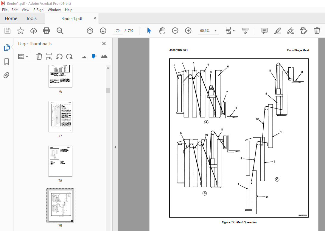
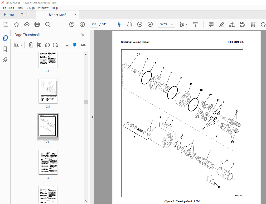
TABLE OF CONTENTS:
Yale Forklift D807 (ERP1.6-2.0ATF) Service Manual – PDF DOWNLOAD
524150790-2100YRM0103-(03-2007)-UK-EN 1
toc 1
Tilt Cylinders 1
Safety Precautions Maintenance and Repair 2
General 5
Description 5
Tilt Cylinder Repair 5
Remove 5
Disassemble 5
Clean 5
Assemble 6
Tilt Cylinders With O-Ring or Single-Lip Seals 6
Tilt Cylinders 7
Install 8
Tilt Cylinder Leak Check 10
Tilt Cylinder Stroke and Mast Tilt Angle Adjustment 11
Torque Specifications 11
Piston Rod Nut 11
Retainer 11
Troubleshooting 12
tables 1
Table 1 Movement Rates (Maximum) for Tilt Cylinders 10
524150797-8000YRM0231-(03-2020)-UK-EN 17
General 21
Threaded Fasteners 21
Nomenclature, Threads 21
Strength Identification 22
Cotter (Split) Pins 23
Fastener Torque Tables 28
Conversion Table 30
524158040-2240YRM0001-(03-2020)-UK-EN 37
General 41
Battery Type 41
Lead-Acid Batteries 41
Lithium-Ion Batteries 42
Specific Gravity 42
Chemical Reaction in a Cell 42
Electrical Terms 44
Battery Selection 44
Battery Voltage 45
Battery as a Counterweight 46
Battery Ratings 46
Kilowatt-Hours 46
Battery Maintenance 46
Safety Procedures 46
Maintenance Records 47
New Battery 47
Cleaning Battery 47
Adding Water to Battery 49
Hydrometer 50
Battery Temperature 51
Charging Battery 52
Types of Battery Charges 52
Methods of Charging 54
Troubleshooting Charger 54
Knowing When Battery Is Fully Charged 55
Where to Charge Batteries 55
Equipment Needed 55
Battery Connectors 56
Battery Care 56
Troubleshooting 58
524158890-4000YRM0521-(03-2006)-UK-EN 63
toc 63
Mast 63
Safety Precautions Maintenance and Repair 64
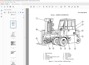
General 67
Description and Operation 67
Carriages 67
Mast Mounts 69
Two-Stage Mast, Limited Free-Lift (LFL) 70
Description and Operation 70
Two-Stage Mast, Full Free-Lift (FFL) 72
Description and Operation 72
Three-Stage Mast, Full Free-Lift (FFL) 74
Description and Operation 74
Four-Stage Mast 76
Description and Operation 76
Cylinder Cushion During Lifting Sequence 80
Cylinder Cushion During Lowering Sequence 81
524158891-4000YRM0522-(07-2010)-UK-EN 85
toc 85
Mast 85
Safety Precautions Maintenance and Repair 86
General 89
Safety Procedures When Working Near Mast 90
Fork Repair 92
Remove 92
Install 92
Carriages Repair 94
Standard Carriage, Remove 94
Hang-On Sideshift Carriage, Remove 95
Standard Carriage and Hang-On Sideshift Carriage, Repair 96
Standard Carriage, Install 97
Hang-On Sideshift Carriage, Install 98
Integral Sideshift Carriage 98
Remove 98
Clean and Inspect 102
Repair 103
Install 104
Mast Repair 105
Remove 105
Two-Stage LFL and Two-Stage FFL Masts, Disassemble 107
Three-Stage FFL Mast 115
Disassemble 115
Mast and Chains, Clean and Inspect 118
Two-Stage LFL and Two-Stage FFL Mast, Assemble 119
Three-Stage FFL Mast, Assemble 120
Install 121
Lift Cylinders Repair 123
Main Lift Cylinders, Remove 123
Free-Lift Cylinder, Remove 123
Cylinders, Disassemble 124
Two-Stage Full Free-Lift Mast, Right-Hand Main Lift Cylinder 124
Two-Stage Full Free-Lift Mast, Left-Hand Main Lift Cylinder 126
Two-Stage Limited Free-Lift Mast and Three-Stage Full Free-Lift 126
Two-Stage Limited Free-Lift Mast and Three-Stage Full Free-Lift 127
Two-Stage Full Free-Lift Mast and Three-Stage Full Free-Lift Mas 128
Clean and Inspect 129
Cylinders, Assemble 129
Two-Stage Full Free-Lift Mast, Right-Hand Main Lift Cylinder 129
Two-Stage Full Free-Lift Mast, Left-Hand Main Lift Cylinder 130
Two-Stage Limited Free-Lift Mast and Three-Stage Full Free-Lift 131
Two-Stage Limited Free-Lift Mast and Three-Stage Full Free-Lift 131
Two-Stage Full Free-Lift Mast and Three-Stage Full Free-Lift Mas 132
Main Lift Cylinders, Install 133
Free-Lift Cylinder, Install 133
Header Hose Arrangements 134
Two-Stage LFL Mast, New Hose Install 134
Two-Stage LFL Mast, Adjust Hoses After Installation 139
Two-Stage FFL Mast, New Hose Install 139
Two-Stage FFL Mast, Adjust Hoses After Installation 147
Three-Stage FFL Mast, New Hose Install 147
Three-Stage FFL Mast, Adjust Hoses After Installation 158
Header Hose Arrangement 159
Two-Stage LFL Mast, New Hose Install 159
Two-Stage LFL Mast, Adjust Hoses After Installation 164
Two-Stage FFL Mast, New Hose Install 164
Two-Stage FFL Mast, Adjust Hoses After Installation 170
Three-Stage FFL Mast, New Hose Install 170
Three-Stage FFL Mast, Adjust Hoses After Install 179
Lift and Tilt System Leak Check 180
Lift Cylinders Leak Check 180
Tilt Cylinders Leak Check 180
Tilt Cylinders Adjustment 181
Lift Chains Adjustment 183
Mast Adjustment 185
Carriage Adjustment 187
Troubleshooting 188
tables 85
Table 1 Hook-Type Carriage Chain Adjustment 183
Table 2 Pin-Type Carriage Chain Adjustment 184
524164212-0100YRM0588-(04-2002)-UK-EN 191
toc 191
Frame 191
Safety Precautions Maintenance and Repair 192
General 195
Description 195
Overhead Guard Repair 196
Remove 196
Install 197
Hood and Seat Assembly Repair 197
Remove 199
Install 199
Counterweight Repair 199
Remove 199
Install 200
Auxiliary Counterweight Repair 201
Remove 201
Install 201
Hydraulic Tank Repair 202
Inspect 202
Small Leaks, Repair 202
Large Leaks, Repair 202
Clean 202
Steam Method 202
Chemical Solution Method 202
Additional Preparations for Repair 203
Safety Labels 203
Battery Size Specifications 205
tables 191
Table 1 Battery Platform Weights 200
Table 2 Battery Size Specifications – Type: Lead-Acid Battery 205
524164213-1300YRM0568-(04-2002)-UK-EN 209
toc 209
Transaxle 209
Safety Precautions Maintenance and Repair 210
General 213
Lubrication 214
Transaxle Repair 214
Remove 214
Inspect 215
Install 215
S2 Series Transaxle 216
Disassemble 216
Inspection 218
Assemble 218
General 218
Ring Gear, Install 218
Intermediate Shaft, Install 219
Axle Shaft, Install 219
Pinion Gear, Install 220
Final Assembly 223
S1 Series Transaxle 224
Disassemble 224
Assemble 226
Troubleshooting 227
tables 209
Table 1 Transaxle Identification 213
Table 2 Transaxle Specifications 213
Table 3 Gear Teeth Contact Pattern 222
524164214-1600YRM0655-(04-2002)-UK-EN 231
toc 231
Steering Housing and Steering Control Unit 231
Safety Precautions Maintenance and Repair 232
General 235
Description 235
Operation 236
Steering Housing Repair 236
Remove and Disassemble 236
Clean 236
Assemble and Install 236
Steering Control Unit Repair 239
Remove 239
Disassemble 239
Clean 239
Assemble 240
Install 240
System Air Removal 240
Troubleshooting 240
524164215-1600YRM0687-(04-2002)-UK-EN 245
toc 245
Steering System 245
Safety Precautions Maintenance and Repair 246
General 249
Operation 249
Steering Wheel and Column Assembly 250
Description 250
Remove 250
Install 253
Power Steering Pump and Motor 254
Description 254
Remove 254
Install 256
Disassemble 256
Assemble 257
Steering Axle Components 258
General 258
Wheel and Tire Assembly 258
Remove 258
Install 259
Wheel Hub Assembly 259
Remove 259
Install 259
Steering Axle Assembly 259
Remove 259
Clean 260
Install 262
Steering System Air Removal 262
Operation Check 263
Steering Pressure Check 263
Troubleshooting 263
524164216-1800YRM0570-(04-2002)-UK-EN 269
toc 269
Brake System 269
Safety Precautions Maintenance and Repair 270
General 273
Description 273
Service Brake Pads Repair 273
Remove 273
Install 273
Service Brake Caliper Repair 274
Remove 274
Install 275
Disassemble 275
Assemble 276
Park Brake Caliper Repair 276
Remove 276
Install 276
Disassemble 277
Assemble 277
Master Cylinder Repair 278
Remove 278
Install 278
Disassemble 278
Assemble 279
Foot-Operated Park Brake Lever Assembly Repair 279
Remove 279
Install 281
Electrically Released Park Brake Repair 282
Mechanical Operation 282
Remove 282
Install 285
Electrically Released Park Brake – Electrical Components Repair 286
Control Box 286
Remove 286
Install 286
Terminal Block 286
Remove 286
Install 288
Park Brake Adjustment 288
Service Brake Adjustment 289
Brake System Air Removal 289
Troubleshooting 290
524164217-2000YRM0576-(04-2002)-UK-EN 295
toc 295
Main Control Valve 295
Safety Precautions Maintenance and Repair 296
General 299
Description 299
Operation 300
Lift Section 301
Tilt Section 301
Tilt Backward 301
Tilt Forward 301
Relief Valve 301
Main Control Valve Repair 301
Remove 301
Install 304
Disassemble 305
Clean and Inspect 307
Assemble 307
Relief Valve Check 308
Vane Settings Adjustment 308
Mast Tilt Adjustment 309
Troubleshooting 310
524164218-2200YRM0697-(08-2005)-UK-EN 315
toc 315
SX/SR Transistor Motor Controller and Handset 315
Safety Precautions Maintenance and Repair 316
Introduction to SEM 319
Advantages of Transistorized SEM 319
Features of SEM 320
Solid-State Reversing 320
Performance and Efficiency 320
Field Weakening 320
Regenerative Braking 320
SX Transistor Motor Controllers 321
Introduction 321
Proportional Operation for Dual-Motor Trucks 321
General 321
Operation 323
Controller Features 325
General 325
Creep Speed 325
Controlled Acceleration 325
Current Limit 325
Braking 325
Regenerative Braking to Zero Speed 325
Pedal Position Braking 326
Auto Braking 326
Conventional Plug Braking 326
Auxiliary Speed Control 326
Field Weakening 326
Speed Limits 326
Ramp Operation 326
Ramp Start 326
Antirollback 327
Steer Pump Contactor Time Delay 327
On-Board Coil Drivers and Internal Coil Suppression 327
System Protective Override 327
SRO (Static Return to Off) 327
Accelerator Volts Hold Off 327
Pulse Monitor Trip (PMT) 327
Thermal Protector (TP) 327
Low Voltage 327
SR Lift Pump Controllers 328
Sensor Interface/Contactor Driver Module 332
Diagnostic Status Codes and Troubleshooting 332
General Maintenance Instructions 332
Special Precautions 332
Diagnostics 333
Systems Diagnostics 333
Status Codes 333
Standard Status Codes 333
Stored Status Codes 333
Other Features 334
Hourmeter Readings 334
Maintenance Alert and Speed Limit 334
Battery Discharge Indication (BDI) 334
Internal Resistance Compensation 334
Handset Programmable 334
RS 232 Communication Ports 334
Circuit Board Coil Driver Modules 334
Maintenance Management Capability 334
Interactive Instrument Panel Modes 335
General Troubleshooting Instructions 337
Status Code Troubleshooting Tables 338
SX/SR Handset Instructions 374
General Features 374
Connecting the Handset 376
Startup Sequence 376
Setup Mode 377
Stored Status Code Mode 378
Clearing the Stored Status Codes 378
Restarting Lift Truck 378
SX Traction Controller Function Descriptions 379
Premium Instrument Panel Interactive Modes 386
SR Pump Controller Function Descriptions 388
Premium Instrument Panel Interactive Modes 391
tables 315
Table 1 SX Traction Controller Connections/Descriptions 322
Table 2 SR Lift Pump Controller Connections/Descriptions/Status 329
Table 3 Instrument Panel Function Number Correlation 335
Table 4 Traction Function Settings Logic 336
Table 5 Lift Pump Function Settings Logic 336
Table 6 Speed/Torque Compensation 390
Table 7 Traction Controller Settings – Standard With Auto Regen 393
Table 8 Traction Controller Settings – Standard Without Auto Re 394
Table 9 Traction Controller Settings – High Performance With Au 396
Table 10 Lift Pump Controller Settings 397
524164219-2200YRM0698-(04-2002)-UK-EN 401
toc 401
Electrical System 401
Safety Precautions Maintenance and Repair 402
General 405
Electrical Compartment 406
Instrument Panels 412
Standard Display (Current Configuration) 412
Premium Display (Current Configuration) 413
Replacement (Current Configuration) 414
Control and Power Fuses 415
Steer Angle Potentiometer 415
General 415
Operation 415
Example 416
Installation 417
Positioning Steer Tire for Straight Travel 417
Adjustment 417
Handset Method 418
Voltmeter Method 418
Testing 420
Power Steering Control Assembly 420
General 420
Operation 420
Testing 421
Removal and Replacement 423
Power Steering Control Assembly 423
Optical Encoder 423
Lift Pump Control Board 424
General 424
Testing 424
Bypassing Lift Pump Control Board 428
Sensor Interface/Contactor Driver Module 428
General 428
Troubleshooting 430
Other Control Components 431
Key Switch 432
Seat Switch 432
Replace 433
Parking Brake Switch 433
Check 433
Replace 434
Accelerator Switch Assembly 434
Check 435
Replace 435
Direction Switches ( Foot Directional Control Pedal) 435
Check 435
Replace 435
Direction Switches (Steering Column) 436
Check 436
Replace 436
Brake Fluid Switch 436
Hydraulic Cutoff Switch 436
Check 437
Replace 437
Stop Light Switch 437
Check 437
Replace 438
Motor Temperature Switches 438
Rocker Switches for Lights 438
DC-to-DC Converter 439
Backup Light Relay Panel 439
Backup Light Switch Relay 440
Horn and Horn Button 440
Horn 440
Horn Switch and Cover (Button) 441
Lights and Reverse Alarm 441
Light Assemblies Replacement 443
Tail Light 443
Flashing Light Assembly 443
Front Driving Light and Rear Work Light Assemblies 444
Spot Light Assembly 447
tables 401
Table 1 Potentiometer Specifications 420
Table 2 Power Steering Control Assembly Specifications 421
Table 3 Lift Pump Control Board Test Point/Function Relationshi 425
Table 4 Lift Pump Control Board Troubleshooting Guide 426
Table 5 Lift Pump Control Board Test Values 427
Table 6 Lift Pump Control Board Bypass Test 428
Table 7 SICDM Connections/Descriptions/Status Codes 429
524164220-2200YRM0779-(06-2005)-UK-EN 451
toc 451
SR/SP Transistor Motor Controller and Handset 451
Safety Precautions Maintenance and Repair 452
Introduction to SEM 455
Advantages of Transistorized SEM 455
Features of SEM 455
Solid-State Reversing 455
Performance and Efficiency 455
Field Weakening 455
Regenerative Braking 455
SR Transistor Traction Motor Controllers 456
Introduction 456
Proportional Operation for Dual-Motor Trucks 456
General 456
Operation 459
Controller Features 459
General 459
Creep Speed 459
Controlled Acceleration 460
Current Limit 460
Braking 460
Regenerative Braking to Zero Speed 460
Pedal Position Braking 460
Auto Regenerative Braking 460
Conventional Plug Braking 460
Auxiliary Speed Control 461
Field Weakening 461
Speed Limits 461
Ramp Operation 461
Ramp Start 461
Antirollback 461
Steer Pump Contactor Time Delay 461
On-Board Coil Drivers and Internal Coil Suppression 461
System Protective Override 461
SRO (Static Return to Off) 461
Accelerator Volts Hold Off 461
Pulse Monitor Trip (PMT) 462
Thermal Protector (TP) 462
Low Voltage 462
SP Lift Pump Controllers 462
Sensor Interface/Contactor Driver Module 466
Diagnostic Status Codes and Troubleshooting 466
General Maintenance Instructions 466
Special Precautions 466
Diagnostics 467
Systems Diagnostics 467
Status Codes 467
Standard Status Codes 467
Stored Status Codes 468
Other Features 468
Hourmeter Readings 468
Maintenance Alert and Speed Limit 468
Battery Discharge Indication (BDI) 468
Internal Resistance Compensation 468
Handset Programmable 468
RS 232 Communication Ports 468
Circuit Board Coil Driver Modules 468
Maintenance Management Capability 469
Interactive Instrument Panel Modes (Premium Only) 469
General Troubleshooting Instructions 471
Status Code Troubleshooting Tables 472
Description 472
SR/SP Handset Instructions 510
General Features 510
Connecting Handset 512
Startup Sequence 513
Setup Mode 514
Stored Status Code Mode 514
Clearing Stored Status Codes 515
Restarting Lift Truck 515
SR Traction Controller Function Descriptions 516
Premium Instrument Panel Interactive Modes 522
SP Pump Controller Function Descriptions 525
Premium Instrument Panel Interactive Modes 528
tables 451
Table 1 SR Traction Controller Connections/Descriptions 458
Table 2 SP Lift Pump Controller Connections/Descriptions/Status 463
Table 3 Instrument Panel Function Number Correlation 469
Table 4 Traction Function Settings Logic 470
Table 5 Lift Pump Function Settings Logic 471
Table 6 Speed/Torque Compensation 527
524164221-8000YRM0586-(04-2002)-UK-EN 533
toc 533
Capacities and Specifications 533
Safety Precautions Maintenance and Repair 534
Wheels and Tires 537
Motors (Dual Voltage 36/48) 537
Mast Tilt Performance 537
Mast Speeds 538
19cc Pump One- and Two-Speed Contactor 538
19cc Pump Transistor Control 539
12cc Pump One- and Two-Speed Contactor 540
12cc Pump Transistor Control 541
Mast/Tilt Drift Speeds 541
Hydraulic System 542
Torque Specifications 542
Frame 542
Transaxle 542
Brake System 542
Wheels 542
Steering System 543
Hydraulic System 543
Mast/Tilt/Attachment Systems 543
Accelerator Potentiometer Checks 543
Adjustments 544
EV 100 LX Traction Card 544
EV 100 LX Pump Card 544
Controller Settings 545
SR/SP Traction Controller Settings – Standard With Auto Regen 545
SR/SP Traction Controller Settings – Standard Without Auto Decel 547
SR/SP Lift Pump Controller Settings 548
SR/SP Traction Controller Settings – 36V Energy Option 549
Battery Size Specifications 550
Type: Lead Acid Battery 550
524164222-8000YRM0696-(04-2002)-UK-EN 555
toc 555
Diagrams 555
Safety Precautions Maintenance and Repair 556
524164223-8000YRM0699-(10-2007)-UK-EN 601
toc 601
Periodic Maintenance 601
Safety Precautions Maintenance and Repair 602
General 605
How to Move Disabled Lift Truck 605
How to Tow Lift Truck 605
How to Put Lift Truck on Blocks 606
How to Raise Drive Tires 606
How to Raise Steer Tires 607
Maintenance Schedule 607
Maintenance Procedures Every 8 Hours or Daily 610
Before Operation Checks 610
Hydraulic System 610
Battery 611
Battery Restraint System 611
Tires and Wheels 612
Safety Procedures When Working Near Mast 613
Forks 615
Adjust 615
Remove 615
Inspect 616
Install 617
Mast and Lift Chains 617
Lift Chain, Adjustment 617
Operation Check 618
Gauges and Horn 618
Control Levers and Pedals 618
Service Brakes 618
Parking Brake 619
Steering System 619
Maintenance Procedures Every 500 Hours or 3 Months 619
Hydraulic Tank Breather 619
Wheel Nut Torque 619
Steering Actuator Mounting Bolts 619
Transaxle 620
Lift System Operation 620
Mast 621
Lift Chains 622
Forks 623
Safety Labels 623
Brake Fluid 623
Other Lubrication 624
Electrical Inspection 624
Special Precautions 624
Contactors 625
Motor Brushes 625
Parking Brake 625
Maintenance Procedures Every 2000 Hours or Yearly 632
Hydraulic System 632
Hydraulic Oil Filter, Change 632
Hydraulic Oil Strainer, Check 632
Hydraulic Oil, Change 632
Brakes 632
Parking Brake, Adjust 633
Transaxle 633
Maintenance Procedures Every 4000 Hours 635
Transaxle 635
Lift and Tilt System Leak Check 635
Lift System 635
Tilt System 636
Battery Maintenance 636
How to Charge Battery 636
How to Change Battery 637
Battery Size Specifications 638
Wheels and Tires Maintenance 639
General 639
How to Change Tires 640
Steer and Drive Wheels 640
Pneumatic Tires 641
Remove Wheel From Lift Truck 641
Tire Sizes and Pressures 641
Remove Tire From Wheel 642
Install Tire on Wheel 643
Add Air to Tires 644
Pneumatic-Shaped Solid Tires 645
Remove Wheel From Lift Truck 645
Press Tire From Wheel 645
Install Tire on Wheel 647
Install Wheel and Tire 648
tables 601
Table 1 Maintenance Schedule 608
Table 2 Transaxle Specifications 634
Table 3 Battery Size Specifications – Type: Lead-Acid Battery 638
524166844-2200YRM0942-(08-2007)-UK-EN 651
toc 651
Display Panel for SEM Controls 651
Safety Precautions Maintenance and Repair 652
General 655
SEM Display Panel Features 655
Descriptions of Common Features 655
LED Symbol Indicators 655
LCD Screen 655
Battery Discharge Indicator (BDI) 656
Service Reminder 656
Status Codes 656
Hourmeter 656
Additional Features of Premium Display Panel 656
Descriptions of Additional Features (Available With Premium Disp 656
LCD Screen 656
Operator Passwords 657
Daily Check List and Service Items 657
Performance Modes 657
Status Code Lists 657
Adjustment of BDI 657
SEM Display Panel Indicators 658
All Indicator Symbols 658
Hourmeter Indicator Symbol 658
Wrench Indicator Symbol 658
Battery Indicator Symbol 658
Battery State-of-Charge (BDI) 658
Brake Fluid Too Low Symbol 659
Parking Brake Symbol 659
Fasten Seat Belt Symbol 659
LCD Screen (Standard Display Panel) 660
Additional Components of Premium Display Panel 660
Alphanumeric Screen 660
STAR Push Button 660
Push Buttons 1 Through 5 660
Adjustments With a Computer 660
Computer System 660
Connect PC to SEM Display Panel 661
ITW Switches Windows Software Program (for SEM Display Panel) 662
Description 662
Getting Help 662
Hardware and Software Requirements 662
Install 662
How to Start ITW Switches Program 662
Menus 666
Sample Sessions 675
Replacement 697
SEM Display Panel 697
Remove and Replace 697
tables 651
Table 1 Adapter Pins (DB25F to DB9) 661
524167640-2200YRM0947-(08-2007)-UK-EN 703
toc 703
Troubleshooting and Adjustments With a Computer 703
Safety Precautions Maintenance and Repair 704
Computer System 707
Connect a PC to a Control Card 708
Installation 709
SMARTSET™ Windows Software Program 709
How to Start the Program 709
DEMO Mode 710
Selecting the Communications Port 712
Verification of Controller and Lift Truck 713
Select Lift Truck Series 715
Controller Card Register Parameter List 716
How to Change a Parameter 717
How to Save a Changed Parameter File 718
How to Load a Saved Parameter File 720
How to Show and Remove Saved Parameter Files 720
How to Return to Factory Default Settings 721
How to Save Changes to Control Card 722
How to View Status Codes 723
Saving Status Codes 724
How to Show and Remove Saved Status Code Files 725
Closing and Clearing Status Code List 726
How to View Saved Register Data and Saved Status Data 727
How to Save Register Data and Status Code Data In RTF and TXT 729
GE Sentry™ Software Program 730
Installation 730
Description 730
How to Start GE SENTRY Program 730
How to Reset MIN and MAX Display 735
Graphing Mode 736
How to Exit GE SENTRY Program 737
tables 703
Table 1 Cable Connections – Computer to Control 707
Table 2 Adapter Pins (DB25F to DB9) 708
Table 3 Plug-Z Connection 709
More products