$42.95
Yale Forklift D877 (GDPGLP300EB, GDPGLP330EB, GDGLPP360EB) Service Manual PDF
Yale Forklift D877 (GDPGLP300EB, GDPGLP330EB, GDGLPP360EB) Service Manual – PDF DOWNLOAD
FILE DETAILS:
Yale Forklift D877 (GDPGLP300EB, GDPGLP330EB, GDGLPP360EB) Service Manual – PDF DOWNLOAD
Language : English
Pages : 1298
Downloadable : Yes
File Type : PDF
IMAGES PREVIEW OF THE MANUAL:
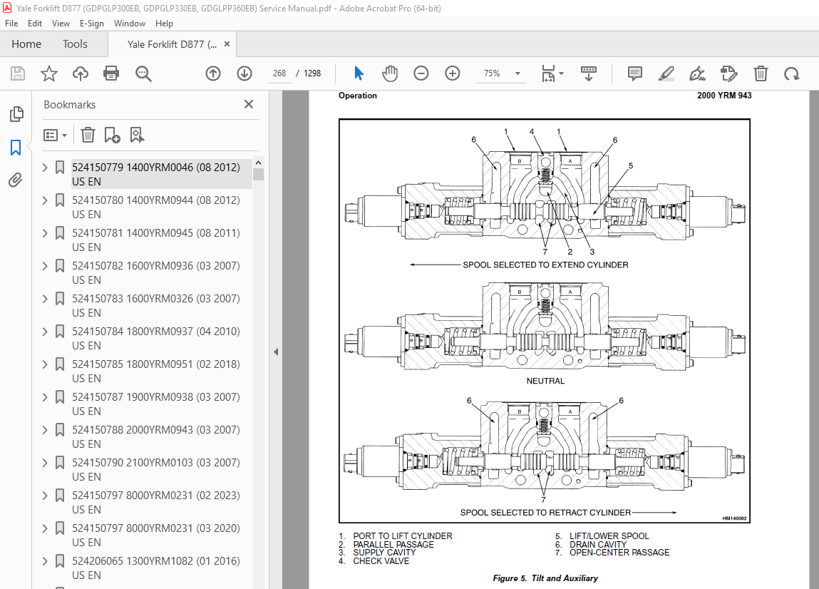
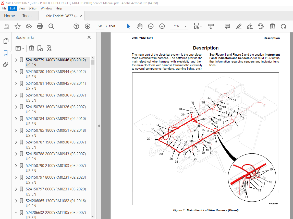
TABLE OF CONTENTS:
Yale Forklift D877 (GDPGLP300EB, GDPGLP330EB, GDGLPP360EB) Service Manual – PDF DOWNLOAD
524150779 1400YRM0046 (08 2012) US EN 1
toc 1
Differential 1
Safety Precautions Maintenance and Repair 2
General 5
Description 5
Differential Repair 5
Remove 5
Differential Carrier From Axle Housing, Remove 5
Differential and Ring Gear From Differential Carrier, Remove 9
Drive Pinion and Pinion Carrier From Differential Carrier, Remov 11
Disassemble 12
Differential and Ring Gear Assembly, Disassemble 12
Drive Pinion and Pinion Carrier, Disassemble 13
Clean and Inspect 16
Assemble 17
Pinion, Bearings, and Pinion Carrier, Assemble 17
Pinion Bearings, Adjust Preload 17
Press Method 17
Yoke or Flange Method 18
Triple-Lip Seal, Install 19
Pinion Carrier Shim Set, Adjust Thickness (Depth of Pinion) 20
Differential and Ring Gear, Assemble 22
Differential Gears Rotating Torque, Check 24
Differential and Ring Gear Assembly, Install 25
Differential Bearings, Preload Adjust 26
Ring Gear, Runout Check 27
Ring Gear Backlash, Adjust 28
Gear Set, Tooth Contact Pattern Check 30
Thrust Screw, Install and Adjust 33
Install 33
Differential Assembly Into Axle Housing, Install 33
Specifications 34
Troubleshooting 38
tables 1
Table 1 Ring Gear Backlash Adjustment Specifications 29
Table 2 Ring and Pinion Tooth Contact Adjustment 30
Table 3 General Specifications 34
Table 4 Rivet Installation Pressure 34
Table 5 Pinion Adjustment 34
Table 6 Pinion Preload Pressure 35
Table 7 Torque Specifications 36
Table 8 Torque Specifications for Metric Hardware 37
Table 9 Torque Specifications for Metric (Fine) Hardware 37
524150780 1400YRM0944 (08 2012) US EN 41
toc 41
Planetary Drive Axle 41
Safety Precautions Maintenance and Repair 42
General 45
Description 45
Operation 47
Identification 47
Removal 48
Disassembly 48
Planetary Spider and Gearing Assembly GDP80-120DB (GP170-280DB) 49
Planetary Spider and Gearing Assembly GDP130-160EB (GP300-360EB) 50
Wheel End 52
Spindle and Piston Housing 53
Cleaning 54
Clean Ground or Polished Parts 54
Clean Parts With Rough Finish 54
Clean Axle Assemblies 54
Drying Cleaned Parts 54
Corrosion Prevention 54
Parts Inspection 55
Tapered Roller Bearings 55
Bevel Pinion and Ring Gear Sets 56
Main Differential Assembly 56
Axle Shafts 56
Yoke 56
Brakes 56
Repair or Replace Parts 56
Repair Welding 57
Apply Silicone Gasket Material 57
Assembly 57
Spindle and Piston Housing to Axle Housing 57
Wet Disc Brakes 58
Adjust Wheel Bearing Preload 59
Planetary Spider and Gearing Assembly GDP80-120DB (GP170-280DB) 60
Planetary Spider and Gearing Assembly GDP130-160EB (GP300-360EB) 60
Planetary Spider Assembly 61
Installation 62
Fill Wet Disc Brakes With Hydraulic Fluid 62
Torque Specifications 63
Lubrication Specification 64
524150781 1400YRM0945 (08 2011) US EN 67
toc 67
Planetary Drive Axle 67
Safety Precautions Maintenance and Repair 68
General 71
Description 71
Operation 73
Identification 73
Removal 74
Disassembly 75
Brake Drum 75
Planetary Spider and Gearing Assembly GDP/GLP80-120DB (GDP/GLP17 76
Dry Brakes 76
Planetary Spider and Gearing Assembly GDP/GLP130-160EB (GDP/GLP3 78
Spindle and Brake Spider 80
Cleaning 80
Ground or Polished Parts 80
Parts With Rough Finish 81
Axle Assemblies 81
Drying Cleaned Parts 81
Corrosion Prevention 81
Parts Inspection 81
Tapered Roller Bearings 81
Bevel Pinion and Ring Gear Sets 82
Main Differential Assembly 83
Axle Shafts 83
Yoke 83
Brakes 83
Repair or Replace Parts 83
Repair Welding 83
Apply Silicone Gasket Material 83
Assembly 84
Spindle, Brake Spider, and Brake 84
Wheel End 85
Adjust Wheel Bearing Preload 85
Planetary Spider and Gearing Assembly GDP/GLP80-120DB (GDP/GLP17 86
Planetary Spider and Gearing Assembly GDP/GLP130-160EB (GDP/GLP3 87
Planetary Spider Assembly 87
Installation 88
Torque Specifications 89
Lubrication Specification 90
524150782 1600YRM0936 (03 2007) US EN 93
toc 93
Steering System 93
Safety Precautions Maintenance and Repair 94
General 97
Description 97
Steering Wheel and Column Assembly 99
General 99
Steering Wheel and Horn 99
Remove 99
Install 99
Steering Control Unit Repair 101
General 101
Description 101
Operation 101
Remove 102
Disassemble 102
Clean 105
Assemble and Install 105
Steering System Air Removal 111
Steering Relief Pressure Check 112
Troubleshooting 112
524150783 1600YRM0326 (03 2007) US EN 117
toc 117
Steering Axle 117
Safety Precautions Maintenance and Repair 118
General 121
Description 121
Steering Axle Assembly Repair 126
Steering Axle GP/GLP/GDP070-110LG/MG (B813), GC/GLC070-120LG/MG 126
Remove 126
Install 126
Steering Axle GDP60-70CA (GP/GLP/GDP135-155CA) (A878, B878), GLP 127
Remove 127
Install 127
Wheels and Hubs Repair (All Units) 128
Remove and Disassemble 128
Clean 128
Inspect 128
Assemble and Install 128
Spindles and Bearings Repair (All Units) 130
Remove 130
Clean 130
Assemble and Install 131
Tie Rods Repair (All Units) 132
Remove 132
Clean 132
Install 132
Steering Cylinder Repair 135
Remove and Disassemble 135
Clean and Inspect 135
Assemble and Install 135
Troubleshooting 136
524150784 1800YRM0937 (04 2010) US EN 141
toc 141
Dry Brake System 141
Safety Precautions Maintenance and Repair 142
General 145
Description 145
Operation 146
Service Brakes 146
Parking Brake 147
Air Tank Repair 148
Relief Valve 148
Drain Valve 149
Brake Pedal Valve Repair 149
Remove 149
Disassemble, Inspect, and Assemble 150
Install 150
Air Chambers Repair 151
Remove 151
Disassemble 151
Inspect 151
Assemble 153
Install 153
Actuator Arms Repair 153
Remove 153
Inspect 154
Install 154
Brake Assemblies Repair 155
Brake Shoe, Remove 155
Camshaft, Remove 157
Clean 157
Inspect 158
Camshaft, Install 158
Brake Shoe, Install 159
Air Dryer 159
Description 159
Cartridge 159
Remove 159
Install 159
Filter 161
Remove 161
Install 161
Quick-Release Valve 161
Governor Check and Adjustment for Air Compressor 162
Brake Shoes Adjustment 162
Specifications 164
Troubleshooting 165
Service Brakes 165
Service Brakes, Park Function 167
tables 141
Table 1 Air Chambers Operation 147
524150785 1800YRM0951 (02 2018) US EN 171
General 175
Description and Operation 175
Service Brakes 175
Parking Brake 175
Oil Cooler Circuit 175
Pressure Switch Replacement 178
Accumulators Replacement 179
Brake Treadle Valve Repair 179
Remove and Disassemble 179
Clean and Inspect 180
Assemble and Install 180
Parking Brake Valve Repair 180
Remove 180
Clean and Inspect 180
Repair 180
Install 180
Parking Brake Caliper Repair 180
Remove 180
Disassemble 183
Inspect 183
Install 183
Adjust 183
Brake Pad Repair 184
Inspect 184
Remove 184
Install 184
Seals Repair 184
Remove 184
Install 184
Service Brake Repair 185
Remove and Disassemble 185
Drain Lubricating Oil 185
Drain Coolant Oil 191
Disconnect Brake Lines 191
Wheel End With Outer Bearing on Ring Gear Hub Journal, Lift Truck Models GDP/GLP130-160EB (GP/GDP/GLP300-360EB) 191
Wheel End With Outer Bearing on Spindle Journal, Lift Truck Models GDP/GLP80-120DB (GP/GDP/GLP170-280DB) 192
Brake Disc Housing Assembly Wheel End 193
Brake Piston Housing 194
Brake Piston Housing and Wheel Spindle 195
Inspect 195
Clean 197
Assemble 198
Wheel Spindle 198
Brake Piston Housing 199
Piston Assembly 200
Brake Disc Housing 201
Duo-Cone Face Seal Into Brake Disc Housing and Into Hub 202
Check for Correct Installation of Duo-Cone Seal 204
Wheel Hub to Brake Disc Housing 204
Adjust 205
Fill Brake System With Coolant Oil 206
System Air Removal 206
Adjust Brake With New Disc Pack 206
Coolant Change Intervals 207
Coolant Draining and Filling 207
Wet Brake Noise Reduction 208
General 208
Adding Additive To Transmission 209
Specifications 210
Minimum Brake Disc Thickness 213
Hydraulic Fluid for Brake Actuation 213
Brake Coolant Specifications 213
Coolant Change Intervals 213
Hydraulic Fluid Specifications 213
Troubleshooting 214
524150787 1900YRM0938 (03 2007) US EN 219
toc 219
Hydraulic System 219
Safety Precautions Maintenance and Repair 220
General 223
Description and Operation 223
Hydraulic Tank 223
Hydraulic Pump 224
Steering Priority Flow Valve 224
Pilot Valve 225
Main Control Valve 227
Unloader Valve 228
Hydraulic Operation 229
Checks And Adjustments 232
Quick Disconnect Fittings 232
Steering Priority Flow Valve 232
Steering Relief Pressure 232
Modulator Valve 233
Pilot Valve and Pressure Reducing Valve 233
Accumulator 234
Filter 234
Main Control Valve 234
Relief Pressure Check 234
Check Valves 235
Unloader Valve 235
Hydraulic Pump Repair 236
Remove 236
Disassemble 236
Clean and Inspect 236
Assemble 237
Install 238
Pilot Accumulator Replacement 238
Remove 238
Install 238
Pilot Valve Repair 238
Remove 238
Disassemble 239
Clean and Inspect 239
Assemble 239
Install 240
Control Levers and Joystick Repair 241
Remove 241
Install 241
Calibration and Diagnostics 242
General 242
Description 242
Lever and Joystick Calibration 242
Flow Adjustment 242
Dead Band Value Setting 243
Lowering Delay 244
PWM and I/O Module Readouts 244
Function Disable 245
General Startup 245
Minimum system requirements 245
Install the Hydraulic Controls Program 245
DelayTimeFile (Reset) 245
Select the Processor Speed 246
Hydraulic Controls Program 246
Calibration 247
Joystick/Lever Calibration 247
Levers 247
Joystick 248
Valve Flow Adjustment 248
Diagnostics 249
Calibration System Shutdown 249
LED Diagnostics 250
Electrical Connections 252
Specifications 256
tables 219
Table 1 Main Control Valve Port Settings 225
Table 2 Processor Speed Settings 245
Table 3 PWM Board LED Error Codes 250
Table 4 Altering PT I/O Board LED’s (Old Logic) 251
Table 5 Altering PT I/O Board LED’s (New Logic) 251
Table 6 Fixed PT Logic I/O Boards LED’s 252
Table 7 PWM Driver Module 253
Table 8 Input/Output Module 1 253
Table 9 Input/Output Module 2 254
Table 10 Altering PT 255
Table 11 Fixed PT 255
524150788 2000YRM0943 (03 2007) US EN 259
toc 259
Main Control Valve 259
Safety Precautions Maintenance and Repair 260
General 263
Description 263
Operation 266
Lift Section 266
Tilt/Auxiliary Section 266
Relief Valves 266
Unloader Valve 266
Main Control Valve Repair 269
Remove 269
Disassemble 269
Auxiliary Side 269
Lift Side 269
Clean and Inspect 272
Assemble 272
Auxiliary Side 272
Lift Side 272
Install 272
Pressure Relief Valve Check and Adjustment 273
Check and Adjust 273
Replace 273
Specifications 274
Troubleshooting 274
524150790 2100YRM0103 (03 2007) US EN 279
toc 279
Tilt Cylinders 279
Safety Precautions Maintenance and Repair 280
General 283
Description 283
Tilt Cylinder Repair 283
Remove 283
Disassemble 283
Clean 283
Assemble 284
Tilt Cylinders With O-Ring or Single-Lip Seals 284
Tilt Cylinders 285
Install 286
Tilt Cylinder Leak Check 288
Tilt Cylinder Stroke and Mast Tilt Angle Adjustment 289
Torque Specifications 289
Piston Rod Nut 289
Retainer 289
Troubleshooting 290
tables 279
Table 1 Movement Rates (Maximum) for Tilt Cylinders 288
524150797 8000YRM0231 (02 2023) US EN 295
General 301
Threaded Fasteners 301
Nomenclature, Threads 301
Strength Identification 302
Cotter (Split) Pins 303
Fastener Torque Tables 308
Conversion Table 310
524150797 8000YRM0231 (03 2020) US EN 317
General 321
Threaded Fasteners 321
Nomenclature, Threads 321
Strength Identification 322
Cotter (Split) Pins 323
Fastener Torque Tables 328
Conversion Table 330
524206065 1300YRM1082 (01 2016) US EN 337
Series Code / Model Designation Reference Table 341
Description of Operation 342
General 342
Torque Convertor, Pump Drive, and Pressure Regulating Valve 342
Input Shaft and Directional Clutches 343
Range Clutches 346
Output Section 346
Transmission Controls 346
Operation of the Valve 348
Selection of Range 354
Pressure Switch 354
Electric Solenoid Controls 354
Transmission Specifications 372
Transmission Identification 372
Weight, Dimensions, and Oil Capacity 372
Transmission Repair 373
Disassemble 373
Reverse and Second-Speed Clutch 403
Clean and Inspect 419
Housings 419
Oil Seals and Gaskets 420
Bearings 420
Gears and Shafts 420
Assemble 420
Reverse and Second-Speed Clutch 431
Control Valve Repair 471
Remove 471
Disassemble and Assemble 471
Clean and Inspect 474
Housings 474
Oil Seals and Gaskets 474
Install 474
Stall Test 476
Transmission Calibration and Electrical Troubleshooting 477
Userlink® 477
Connection 477
Clutch Filling Calibration 478
Purpose 478
Clutch Filling Calibration Procedure 478
Alternative Clutch Filling Calibration Procedure 478
Heat-up Mode 479
Heat-up Mode Stall Test 479
Inching Pedal Calibration 480
Purpose 480
Troubleshooting 480
Transmission Display Warning Codes 480
Access 481
Clear 481
Exit 481
Limp Home Mode 518
Shutdown Mode 518
Pressure Feedback Sensor 518
Transmission Oil Pressure Check 519
Pressure and Temperature Specifications 519
Electrical Specifications 525
Hydraulic Cooler Lines Specifications 525
Torque Specifications 526
Torque Specifications for Lubricated or Plated Screw Threads 526
Troubleshooting 528
524206632 2200YRM1105 (03 2007) US EN 535
toc 535
Instrument Panel Indicators and Senders 535
Safety Precautions Maintenance and Repair 536
General 539
Description 539
General 539
Instrument Panel Meters, Indicators, and LCD Display 539
Connector 544
Seat Switch Logic 545
Central Warning Light Output 545
Buzzer Output 545
Instrument Panel 546
Remove 547
Sender Replacement 548
Fuel Level Sender (Diesel Engine Only) 548
Engine Oil Pressure Sender 548
Brake Pressure Sender 548
Low Coolant Sender 549
Vacuum Switch 549
Specifications 550
Troubleshooting 551
tables 535
Table 1 Instrument Panel and Indicators 540
Table 2 Pin Description 544
Table 3 Sender Description 545
524211827 0600YRM1101 (11 2018) US EN 555
Series Code / Model Designation Reference Table 559
General 559
Fault Codes 560
Normal Mode 560
Fault Log Mode 561
Access 561
Exit 561
Clear 561
Electronic Throttle Calibration 561
Electronic Throttle Calibration Procedure 562
Stationary Regeneration Procedure 562
524230692 8000YRM1181 (01 2017) US EN 591
Series Code / Model Designation Reference Table 595
General 596
Weight and Dimensions 596
Loading Procedures 604
Loading A Truck on a Transport 604
Loading Disassembled Components 604
Unloading Procedures 605
Unloading Complete Truck or Basic Truck From Transport 605
Lifting 605
Driving On/Off a Trailer 606
Unloading Disassembled Components 606
Removal of Forks Attached to Basic Truck 606
Removal of Forks Attached to the Carriage 606
Truck Assembly 607
Safety procedures When Working Near the Mast 608
Mast Installation 609
Preparations 609
Adjusting the Tilt Cylinders 611
Connecting the Lift Cylinders 611
Connecting the Mast Supply Hoses 612
Carriage and Forks 613
Installing the Carriage 613
Connecting the Header Hoses to the Carriage 613
Install the Forks 613
Installing Pin-Type Forks 613
Installing Quick Disconnect DFSSFP Forks 615
616
Installing Integrated DFSSFP Forks 616
Adjusting the Carriage 616
Adjusting Header Hose Tension 617
Adjusting the Electrical Cable Tension 618
Installing the Cab Lights 618
Adding the Mast Labels 619
Lubrication Points 619
Pre-Delivery Inspection 620
Empty Seat Engine Shut Down 620
Pre-Delivery Inspection 620
Pneumatic Tires and Wheels 621
Remove Wheels From Lift Truck 621
Remove Tire From Wheel 622
Install Tire on the Wheel 624
Adding Air Pressure to the Tires 626
Solid Rubber Tires, Remove Tire From the Wheel 626
Solid Rubber Tires, Install Tire on the Wheel 628
Install Wheels on Lift Truck 630
Moving and Towing 631
Moving a Disabled Lift Truck 631
Precautions 631
Towing A Lift Truck 632
524298462 8000YRM1346 (05 2007) US EN 635
toc 635
Diagrams 635
Safety Precautions Maintenance and Repair 636
524298463 8000YRM1347 (09 2013) US EN 689
toc 689
Periodic Maintenance 689
Safety Precautions Maintenance and Repair 690
General 695
Serial Number Data 695
How to Move a Disabled Lift Truck 696
How to Tow the Lift Truck 696
How to Put a Lift Truck on Blocks 696
How to Raise the Drive Tires 697
How to Raise the Steer Tires 697
How to Clean a Lift Truck 698
Maintenance Schedule 698
Maintenance Procedures Every 8 Hours or Daily 707
How to Make Checks With the Engine Stopped 707
Warning and Safety Labels 707
Wheels, Tires, and Tire Pressure 707
Wheel Nuts 707
Inspection of Forks, Mast, Carriage, Attachment, and Lift Chains 708
Header Hose Assembly 708
Hydraulic Tank Breather 710
Forks, Adjust 710
Forks, Remove 710
Forks, Install 710
Air Precleaner Dust Bowl 710
Check for Fuel, Oil, or Coolant Leaks 711
Engine Air Intake Piping and Charge Air Piping 711
Drive Belts 711
Radiator Sections for Engine Coolant, Charge Air Cooler, Transmi 711
Engine Compartment 711
Hydraulic System Oil 711
Windshield Washer Fluid 712
Coolant Level 712
Engine Oil 712
How to Add Fuel to the Lift Truck 715
Diesel Fuel 715
Liquefied Petroleum Gas (LPG) 716
Remove 716
Fill 716
Install 717
How to Make Checks With the Engine Running 717
Operator Restraint System (Seat Belt and Seat Rails) 717
Steering Column Latch 717
Gauges, Lights, Horn, Fuses, and Relays 718
Windows and Mirrors 723
Engine and Transmission Fault Codes 723
Engine Air Filter 723
Diesel Fuel Filter/Water Separator 723
Cooling System 723
Fuel System 724
Control Levers, Switches, and Pedals 724
Steering System 724
Parking Brake 724
Service Brakes 724
Mast, Carriage, and Attachment 724
Signals from the Spreader Control System 725
Operator Presence System (OPS) 725
Transmission 725
Transmission Oil Level 725
First Inspection After First 100 Hours of Operation 726
Lift Chains 726
Hydraulic System Oil Filter 726
Transmission Oil Filter 726
Hydraulic Pilot Valve Oil Screen 726
Wet Brake System Filter 726
Maintenance Procedures Every 250 Hours or 3 Months 727
Warning and Safety Labels 727
Mast, Carriage, and Attachment 727
Lift Chains 727
Forks 728
Tires and Tire Pressure 728
Wheel Nuts, Drive and Steer Wheels 729
Hydraulic Tank Breather 729
Air Precleaner Dust Bowl 729
Fuel, Oil, and Coolant Leaks 729
Engine Air Intake Piping and Charge Air Piping 729
Coolant Hoses 729
Drive Belts 730
Engine Compartment 730
Radiator Sections for Engine Coolant, Charge Air Cooler, Transmi 730
Drive Axle and Differential 730
Windshield Washer Fluid 730
Hydraulic System Oil 730
Coolant Level 730
Engine Oil Level 731
Fuel Water Separator 731
Transmission Oil Level 731
LPG Crankcase Breather 731
Operator Restraint System (Seat Belt and Seat Rails) 732
Steering Column Latch 732
Operator Presence System (OPS) 732
Chain Sheave Bearings 732
Mast Pivot Pins 732
Carriage Pins, Fork Pins, and Carriage Sliding Surfaces 732
Maintenance Procedures Every 500 Hours or 3 Months 733
Tilt Cylinder Pivot Pins 733
Steering Axle Tie Rod Pins 733
Kingpins 733
Shafts for Air Brake Actuator Arms 733
Maintenance Procedures Every 500 Hours or 6 Months 733
Cab Air Filter 733
Header Hose Assembly 733
Air Compressor (Air Brakes Only) 733
Cooling Fan 733
Cummins Diesel and LPG Engine Oil 733
Engine Oil Filter 734
Diesel Fuel Filter 734
Maintenance Procedures Every 1000 Hours or 6 Months 734
Parking and Service Brakes 734
Coolant Quality 734
LPG Tank Hinges 734
Cab Door Hinges 734
LPG Vapor Fuel Filter 734
Wet Brake System Filter 735
Maintenance Procedures Every 1000 Hours or 1 Year 735
Transmission Oil 735
Transmission Oil Filter 735
Maintenance Procedures Every 1500 Hours or 6 Months 735
Drive Axle and Differential 735
Maintenance Procedures Every 2000 Hours or 1 Year 735
Transmission Clutch Calibration 735
Inching Pedal Sensor Calibration 735
Fan Belt and Tensioner 735
Fan Hub, Belt Hubs, Idler Pulley 736
Vibration Damper 737
Engine and Transmission Mounting 737
Spark Plug (LPG Engines Only) 737
LPG Liquid Fuel Filter 738
Brake System Accumulator 738
Pilot Valve Accumulator 738
Lift System Accumulator (Optional) 739
Drive Shaft 739
Spark Plug Wire (LPG Engine Only) 739
Maintenance Procedures Every 3000 Hours or 1 Year 740
Air Dryer Cartridge 740
Hydraulic System Oil and Filter 740
Hydraulic Pilot Valve Oil Screen 740
Maintenance Procedures Every 5000 Hours or 3 Years 741
Air Conditioning 741
Steering Wheel Hub Bearings 741
Maintenance Procedures Every 5000 Hours or 4 Years 741
Engine Valve Adjustment 741
Safety Procedures When Working Near Mast 741
Lift and Tilt System Leak Check 742
Lift System 742
Tilt System 743
Wheel and Tire Replacement 744
Remove Wheels From Lift Truck 744
Pneumatic Tires 744
Remove Tire From Wheel 744
Remove Tire From Two- and Four-Piece Wheel 745
Install Tire on Wheel 746
Install Tire on Two- and Four-Piece Wheel 746
Add Air to Tires 747
Solid Rubber Tires 748
Remove Tire From Wheel 748
Install Tire on Wheel 749
Wheels, Install 751
tables 689
Table 1 Daily Inspections − Condition Check 700
Table 2 Daily Inspections − Fluid Level Check 701
Table 3 Daily Inspections − Checks With the Engine Running 701
Table 4 Initial 100-Hour Check or Change 702
Table 5 Periodic Maintenance Schedule − Inspect and Adjust 703
Table 6 Periodic Maintenance Schedule − Lubricate 705
Table 7 Periodic Maintenance Schedule − Change 706
Table 8 Approved LPG Engine Oil Types 715
Table 9 Valve Adjustment Specifications 741
Table 10 Allowable Mast Movement from Internal Leakage 743
524298464 8000YRM1348 (07 2013) US EN 755
toc 755
Capacities and Specifications 755
Safety Precautions Maintenance and Repair 756
Counterweight Weights 759
Lift Truck Weights 759
Capacities 760
Engine Specifications 761
Hydraulic System 762
Electrical System 762
Tire Sizes 762
Mast Speeds 763
Torque Specifications, Cummins Diesel 764
Lubrication System 764
Torque Specifications, General 764
Transmission 764
Driveline and Axle 764
Counterweight 764
Differential 764
Brakes – Wet 764
Brakes – Dry 764
Steering 764
Wheel Nuts 765
Hydraulic System 765
Mast 765
Carriage 765
Tilt Cylinders 765
Wiper Arms, Front 765
524300812 0100YRM1349 (11 2015) US EN 769
General 773
Description 774
Air Cleaner 775
Remove 775
Install 775
Exhaust System 776
Remove 776
Install 776
Hood Assembly 777
Remove 777
Install 778
Hydraulic Tank 778
Remove 778
Inspect 780
Clean 781
Additional Preparations for Repair 781
Repair 781
Small Leaks 781
Large Leaks 782
Preparations for use After Repair 782
Install 782
Fuel Tank 783
Remove 783
Repair 787
Install 787
Cab Repair 787
Rear Cab Assembly 788
Bottom Cab Assembly 789
Raising and Lowering Cab 789
Raise Cab 789
Lower Cab 790
Cab Repair 790
Remove 790
Install 791
Engine 792
Remove 792
Install 796
Counterweight 799
General 799
Remove 799
Install 800
Cab 800
Remove 801
Install 802
Label Replacement 803
524300813 0700YRM1350 (05 2012) US EN 807
toc 807
Cooling System 807
Safety Precautions Maintenance and Repair 808
General 811
Cooling System Description 811
Cooling Cores 811
Fan and Shroud 812
Engine Cooling System 812
Water Pump 813
Thermostat 813
Expansion Tank And Radiator Cap 814
Cab Heater 814
Coolant 814
Charge Air Cooling System 816
Transmission Oil Cooling System 816
Hydraulic Oil Cooling System 816
Hydraulic Oil Cooling, D876/D877 Trucks 817
Hydraulic Oil Cooling, E876/E877 Trucks 817
Brake Cooling 818
Oil Filtration and Oil Cooling 818
Hydraulic Control System 818
Service and Repair 819
Cooling System Checks 819
Basic Checks 819
Coolant Quality Checks 819
Coolant Flow Checks 820
Thermostat 820
Water Pump 821
Cooling Core Efficiency 821
Cooling Core Flow Restrictions 821
Engine Leak Tests 822
External Leak Test 822
Check for Coolant Leak Into The Engine Oil Sump 823
Combustion Leak Test 823
Engine Cooling System Maintenance 824
Draining the Engine Cooling System 824
Filling the Engine Cooling System 825
Flushing the Engine Cooling System 825
Cleaning the Engine Cooling System 826
Remove and Replace Procedures 826
Drive Belt 826
Remove 826
Install 826
Belt Tensioner 826
Inspect 826
Remove 826
Install 827
Water Pump 827
Inspect 827
Remove 827
Install 827
Thermostat 828
Remove 828
Inspect 828
Install 828
Cooling Core Assembly 828
Removal 828
Cooling Cores 831
Disassembly 831
Assembly 831
Install 831
tables 807
Table 1 Limiting Values 815
Table 2 Thermostat Operating Temperatures 820
Table 3 Temperature Differences Between Core Entry and Core Exi 821
524300814 2200YRM1351 (04 2007) US EN 837
toc 837
Electrical System 837
Safety Precautions Maintenance and Repair 838
Description 841
Warning Devices 846
General 846
Description 847
Operator-Controlled Horn 847
Reverse Warning Horns/Lights 847
Warning Lights 847
Strobe Light 847
Brake Lights 849
Hazard Lights 849
Replace 849
General 849
Horns 849
Horn Relay 849
Light Assemblies 849
Flashing Unit 850
Meters, Senders, and Switches 850
General 850
524302733 1300YRM1356 (01 2016) US EN 863
Series Code / Model Designation Reference Table 867
General 867
Transmission Repair 867
Remove 867
Disassemble 871
Reverse and Second-Speed Clutch 901
Clean and Inspect 917
Housings 917
Oil Seals and Gaskets 918
Bearings 918
Gears and Shafts 918
Assemble 918
Reverse and Second-Speed Clutch 928
Install 969
Control Valve Removal and Installation 972
Remove 972
Install 972
Control Valve Components 973
Control Valve Disassemble and Assemble 973
Remove 973
Control Valve Cover 973
Control Valve Components 974
Install 974
Control Valve Components 974
Control Valve Cover 974
Transmission Frame Bracket 975
Torque Specifications 975
Torque Specifications for Lubricated or Plated Screw Threads 975
Troubleshooting 977
524304019 1300YRM1358 (01 2016) US EN 981
Series Code / Model Designation Reference Table 987
General 988
Description 988
General 988
Operation 991
Hydraulic Operation 991
1st/3rd Selector Valve 994
Cooling and Lubrication 996
Control System 997
General 998
APC200 Controller 998
Self Test 998
Protection Modes 998
Limp Home Mode 998
Shut Down Mode 998
Transmission Exceed Codes 999
Fault Codes 999
Description 999
Fault Log Mode 999
Access 999
Exit 1000
Clear 1000
Fault Rectification 1000
Hydraulic Control Valve 1002
Hydraulic Control Valve Repair 1004
Solenoid Replacement 1004
Pressure Check 1004
Pressure Specifications 1005
Pressure, Speed, and Temperature Sensors 1005
Pressure Switch 1010
Test 1010
Speed Sensor 1011
Test 1011
Temperature Sensors 1012
Test 1012
Transmission Test and Calibration 1013
Precautions 1013
Stall Test 1013
Description 1013
Stall Test Procedure 1013
Clutch Calibration 1014
Description 1014
Procedure 1015
Inching Calibration 1015
Description 1015
Brake and Inching Pedal Adjustment 1016
Inching Sensor Adjustment 1016
Inching Sensor Calibration 1017
Electrical Specifications 1017
APC200 Display information 1017
General 1018
General Information Group 1018
Fault Codes 1019
Indication of Protection Modes 1019
Test Function Group 1020
Digital Input Test 1022
Analog Input Test 1023
Speed Sensor Test 1024
Output Test 1025
Voltage Test 1026
Calibration Group 1028
Calibration Mode 1028
Clutch Filling Calibration 1028
Heat Up Mode 1029
Inching Sensor Calibration 1029
Inching Pedal Sensor Adjustment 1029
Inching Sensor Calibration 1029
TE-Userlink 1030
Description 1030
Connection 1030
1030
Diagrams, Schematics, or Arrangements 1030
550022606 1300YRM1435 (01 2016) US EN 1067
Series Code / Model Designation Reference Table 1071
General 1071
Transmission Exceed Codes 1071
Clutch Calibration Condition Messages 1071
Fault Codes During Clutch Calibration 1071
APC200 Fault Codes 1072
Limp Home Mode 1072
Shut Down Mode 1072
Pressure Feedback Sensor 1072
APC200 Fault Codes 1073
Transmission Exceed Codes 1073
Clutch Calibration Condition Messages 1077
Fault Codes During Clutch Calibration 1077
APC200 Fault Codes 1080
550033397 0100YRM1458 (04 2011) US EN 1107
toc 1107
Cab Heater (Prior to Oct 2008) 1107
Safety Precautions Maintenance and Repair 1108
Aurora Heater and Air Conditioner 1111
Heater System 1111
General 1111
Air Conditioning 1112
General 1112
Dryer 1113
Control Systems, Sensors, and Switches 1113
Heater System Repair 1115
Heater Assembly 1115
Access 1115
Remove 1115
Install 1115
Heater Assembly Parts, Replace 1116
Heater Core 1116
Remove 1116
Install 1116
Evaporator Core 1117
Remove 1117
Install 1117
Blower 1117
Remove 1117
Install 1117
Water Valve 1118
Remove 1118
Install 1118
Vent Door 1119
Remove 1119
Install 1119
Push/Pull Cable, Replace 1119
Water Valve Cable 1119
Remove 1119
Install 1120
Vent Door Cable 1120
Remove 1120
Install 1121
Electric-Operated Heater Control and Fan Control 1122
Remove 1122
Install 1122
Cable-Operated Heater Control and Air Control 1123
Remove 1123
Install 1123
Air Conditioning Switch 1123
Remove 1123
Install 1123
Technical Detail 1124
tables 1107
Table 1 Air Conditioning Specifications 1124
550033400 0100YRM1390 (12 2018) US EN 1127
Series Code / Model Designation Reference Table 1135
General 1135
Description of Operation 1137
Cab Structure 1137
Cab Tilt System 1137
Cab Tip-Up System 1139
Tilting the Cab 1140
Raising 1140
Lowering 1141
Remove and Install 1142
Cab Door Assembly 1142
Cab Door 1142
Remove 1142
Install 1142
Door Hinge 1143
Remove 1143
Install 1143
Door Latch 1144
Remove 1144
Install 1144
Door Handle 1144
Remove 1144
Install 1144
Door Release 1145
Remove 1145
Install 1145
Door Push Button 1145
Remove 1145
Install 1146
Cab Tilt System 1146
Electric Tilt Pump 1146
Remove 1146
Install 1146
Hand Tilt Pump 1146
Remove 1146
Install 1147
Cab Tilt Cylinder 1148
Remove 1148
Disassemble 1148
Clean 1150
Inspect 1150
Assemble 1150
Install 1151
Latch 1151
Remove 1151
Install 1152
Brake and Inching Pedal 1153
Remove 1153
Install 1153
Accelerator Pedal and Sensor 1154
Remove 1154
Install 1154
Adjust Sensor 1154
Seat Assembly 1154
Seat 1154
Remove 1154
Install 1155
Seat Cushion 1155
Remove 1155
Install 1156
Back Cushion 1156
Remove 1156
Install 1156
Seat Suspension Replacement 1156
Boot Replacement 1156
Power Assist Armrest 1180
Release Cable 1180
Remove 1180
Install 1180
Gas Spring 1180
Remove 1180
Install 1181
Joystick 1181
Remove 1181
Install 1181
Electrical Levers 1181
Remove 1181
Install 1182
Armrest Rocker Switches 1182
Remove 1182
Install 1182
Armrest Top Cover 1182
Remove 1182
Install 1182
Instrument Panel 1183
Key Switch 1183
Remove 1183
Install 1183
12V Power Socket 1183
Remove 1183
Install 1183
Electric-Operated Heat Control and Air Recirculation Control (Airco Only) 1184
Remove 1184
Install 1184
Cable-Operated Heater Control (Heater Only) 1185
Remove 1185
Install 1185
Air Conditioning Switch Replacement 1185
Instrument Panel Rocker Switches Replacement 1185
Parking Brake Switch 1186
Remove 1186
Install 1186
Indicator Display Replacement 1186
Instrument Panel Top Console 1186
Remove 1186
Install 1187
Steering Wheel and Column Assembly 1187
Steering Wheel and Horn 1187
Remove 1187
Install 1189
Steering Column Assembly 1189
Remove 1189
Install 1190
Adjustment Handle 1190
Remove 1190
Install 1190
Main Warning Lights 1191
Remove 1191
Install 1191
Shift Lever 1191
Remove 1191
Install 1191
Turn Signal Lever 1191
Remove 1191
Install 1191
Window Wipers 1192
Window Wiper Assembly Replacement 1192
Remove 1192
Install 1192
Window Wiper Motor Replacement 1192
Front Window Wiper Motor 1192
Install 1192
Rear Window Wiper Motor Assembly 1193
Remove 1193
Install 1193
Top Window Wiper Motor Assembly 1193
Remove 1193
Install 1193
Window Washer System 1194
Window Washer Reservoir and Pumps 1194
Remove 1194
Install 1194
Window Washer Hoses 1195
Hoses for Top and Rear Window 1195
Install 1196
Window Washer Spray Nozzles 1196
Front Window 1196
Remove 1196
Install 1196
Rear Window 1197
Remove 1197
Install 1197
Top Window 1197
Remove 1197
Install 1197
Window Replacement 1197
Front Window 1199
Remove 1199
Install 1199
Rear Window 1199
Remove 1199
Install 1199
Top Window 1200
Remove 1200
Install 1200
Door, Upper/Lower Window 1201
Remove 1201
Install 1201
Sliding Window and Sliding Tracks 1201
Remove 1201
Install 1203
Weather Strip Replacement 1203
Window Stopper Replacement 1203
Window Seal Replacement 1204
Sliding Window Frame 1204
Remove 1204
Install 1204
Floor Mat 1204
Front Floor Mat 1204
Remove 1204
Install 1205
Rear Floor Mat 1205
Remove 1205
Install 1206
Radio Console 1206
Remove 1206
Install 1206
Air Duct Replacement 1207
Remove Front 1207
Remove Rear 1207
Install 1208
Accessories 1208
Mirror Replacement 1208
Sunshade Replacement 1208
Top 1208
Rear 1209
Map Light Replacement 1209
Interior Fan Replacement 1209
Training Seat 1209
Field Installation 1209
Remove 1209
Label Replacement 1210
Checks and Adjustments 1210
Check Oil Level for Cab Tilt System 1210
Door Striker Pin Adjustment 1211
Brake Pedal Adjustment 1211
Dry Brake 1211
Wet Brake 1212
Inching Pedal Adjustment 1212
Inching Pedal Sensor Adjustment 1212
Sensor Adjustment Using Dana Dashboard Software 1212
Sensor Adjustment using the APC200 Display 1213
Sensor Adjustment for Trucks with ZF Transmission 1214
Inching Pedal Sensor Calibration 1214
Sensor Calibration using Dana Dashboard Software 1214
Sensor Calibration using APC200 Display 1214
Sensor Calibration for Trucks with ZF Transmission 1215
550088524 4000YRM1647 (07 2016) US EN 1219
Series Code / Model Designation Reference Table 1225
General 1225
Description And Operation 1225
Mast System 1225
Tilting 1225
Lifting 1226
Operation 1226
Pilot Operated Check Valves 1227
Gland Lubrication 1228
Emergency Lowering Valve 1228
Operation 1228
Lift Chains 1229
Elongation Through Wear 1229
Speed of Wear 1229
Plate Height Wear 1230
Lubrication 1230
Restoring The Oil Film 1230
Maintenance 1230
Maintaining The Presence of Oil 1231
Corrosion Protection 1231
Requirements for Chain Lubricant 1231
Load Rollers 1232
Bearing Blocks 1232
Carriage 1233
Standard Carriage with Manual Fork Positioning 1233
Standard Carriage with Hydraulic Fork Positioning 1233
Dual Function Side Shift and Fork Positioning (DFSSFP) Carriage 1234
Integral Side Shift 1234
Carriage Valve 1235
Alternating Pressure and Tank (P & T) 1235
Fixed Pressure and Tank (P & T) 1235
Flow Divider for Simultaneous Fork Positioning 1235
Valve for Dual Function with Side Shift and Fork Positioning (DFSSFP) 1237
Fixed Pressure and Tank System (Fixed P & T) 1239
Forks 1241
Safety Procedures When Working Near Mast 1242
Before Starting Repairs to the Hydraulic System, Always: 1243
Remove and Replace 1243
Forks 1243
Remove 1243
Install 1244
Fork Guide And Fork Pin 1245
Remove 1245
Install 1245
Carriage 1246
1246
Remove 1246
Install 1247
Carriage Bearing Blocks 1248
Remove 1248
Install 1249
1249
Carriage Load Rollers 1249
Replace 1249
1251
Side Shift Cylinder 1251
Remove 1251
Disassemble 1251
Clean And Inspect 1252
Assemble 1252
Install 1253
Fork Positioner Cylinder 1253
Remove 1253
Disassemble 1254
Clean and Inspect 1254
Assemble 1255
Install 1255
Carriage Valves 1255
Remove 1255
Install 1256
1256
Valve for Fixed P & T Systems 1256
Remove and Disassemble 1256
Clean and Inspect 1258
Assemble and Install 1258
Flow Divider for Simultaneous Fork Positioning Valve 1259
Restrictor Valve and Relief Valve Replacement 1259
Dual Function Valve for Side Shifting and Fork Positioning 1259
Solenoid Valve Replacement 1259
Relief Valve Replacement 1260
Remove 1260
Install 1260
Mast 1260
Lift Chains and Top Chain Anchor 1260
Remove 1260
Install 1260
Chain Anchor On Carriage 1261
Remove 1261
Install 1261
Chain Sheave 1262
Remove 1262
Install 1262
Header Hoses 1263
Remove 1263
Install 1265
Electric Mast Cable 1265
Remove 1265
Install 1265
Hose Sheave 1266
Remove and Disassemble 1266
Assemble and Install 1266
Mast Assembly 1267
Remove 1267
Disassemble 1269
Assemble 1270
Install 1271
Inner Mast Load Rollers 1273
Replace 1273
Mast Bearing Blocks 1274
Remove 1274
Install 1274
Lift Cylinders 1275
Remove 1275
Disassemble 1278
Clean and Inspect 1278
Assemble 1278
Install 1279
Tilt Cylinders 1280
Remove 1280
Disassemble 1281
Clean and Inspect 1281
Assemble 1281
Install 1282
Checks and Adjustments 1283
General Checks 1283
Mast Condition Check 1283
Mast Operation Check 1284
Counterbalance Valve Check (for E876 and E877 Only) 1284
Fork Inspection and Adjustment 1284
Lift Chain Inspection 1285
Lift Chain Lubricant Requirements 1286
Lift Chain Lubrication Procedure 1286
Leak Checks 1286
Mast Vertical Creep 1286
Mast Tilt Drift 1287
Adjustments 1287
Lift Cylinder Shimming 1287
Lift Chain and Fork Height Adjustment 1289
Header Hose Tension Adjustment 1291
Electric Mast Cable Tension Adjustment 1291
Counterbalance Valve Adjustment 1291
Tilt Cylinder Backward Tilt Angle Adjustment 1292
Mast Support Pad Adjustment 1292
Troubleshooting 1292
Introduction 1293
No Hydraulic Movement With Engine Running 1293
Initial Basic Check 1293
1294
Electrical Supply 1294
Hydraulic Supply 1294
Fault Code 1294
No Lowering Possible with Engine OFF 1295
Incorrect Movement 1295
Irregular (shaking) Movement
or
Slight Carriage Movement When Starting Engine
1295
Unequal Movement of Left And Right Tilt Cylinder 1295
Insufficient Lifting Speed 1295
Insufficient Lifting Capacity 1296
Incorrect Lowering Speed 1296
Lift Cylinder Creep 1296
Tilt Cylinder Creep 1296
More products