$41.95
Yale Forklift E108 (ERC040-065RGZG) Service Manual – PDF DOWNLOAD
Yale Forklift E108 (ERC040-065RGZG) Service Manual – PDF DOWNLOAD
FILE DETAILS:
Yale Forklift E108 (ERC040-065RGZG) Service Manual – PDF DOWNLOAD
Language : English
Pages : 1332
Downloadable : Yes
File Type : PDF
IMAGES PREVIEW OF THE MANUAL:
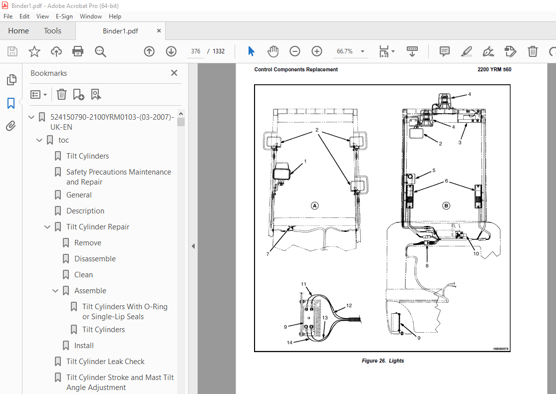
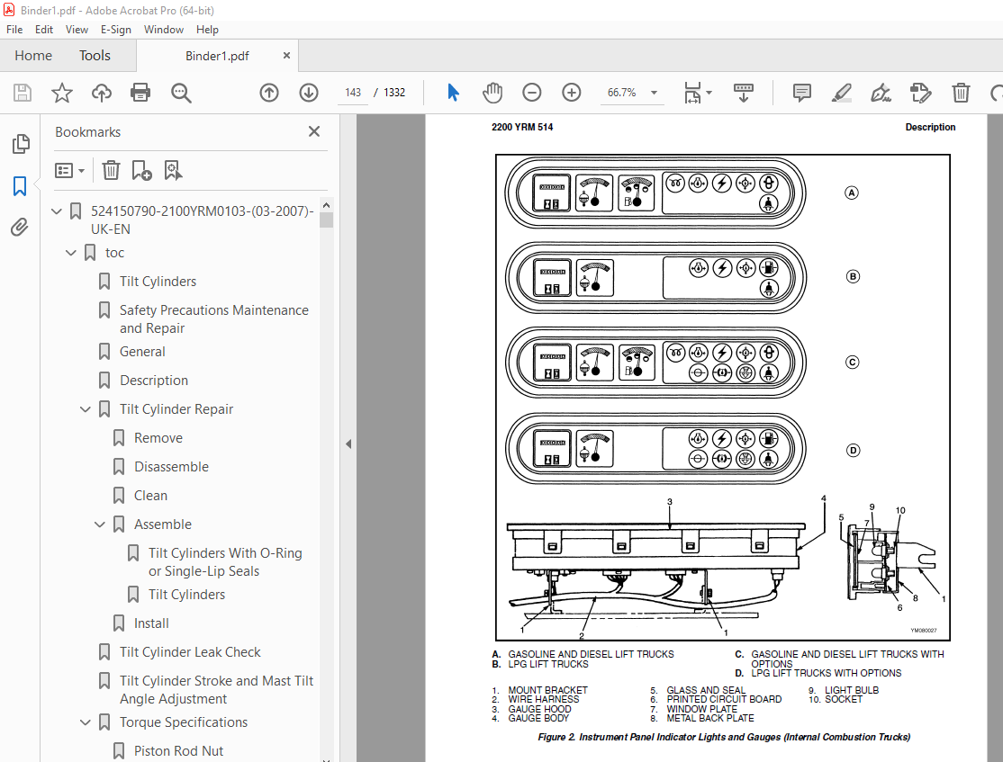
TABLE OF CONTENTS:
Yale Forklift E108 (ERC040-065RGZG) Service Manual – PDF DOWNLOAD
524150790-2100YRM0103-(03-2007)-UK-EN 1
toc 1
Tilt Cylinders 1
Safety Precautions Maintenance and Repair 2
General 5
Description 5
Tilt Cylinder Repair 5
Remove 5
Disassemble 5
Clean 5
Assemble 6
Tilt Cylinders With O-Ring or Single-Lip Seals 6
Tilt Cylinders 7
Install 8
Tilt Cylinder Leak Check 10
Tilt Cylinder Stroke and Mast Tilt Angle Adjustment 11
Torque Specifications 11
Piston Rod Nut 11
Retainer 11
Troubleshooting 12
tables 1
Table 1 Movement Rates (Maximum) for Tilt Cylinders 10
524150797-8000YRM0231-(02-2023)-UK-EN 17
General 23
Threaded Fasteners 23
Nomenclature, Threads 23
Strength Identification 24
Cotter (Split) Pins 25
Fastener Torque Tables 30
Conversion Table 32
524150797-8000YRM0231-(03-2020)-UK-EN 39
General 43
Threaded Fasteners 43
Nomenclature, Threads 43
Strength Identification 44
Cotter (Split) Pins 45
Fastener Torque Tables 50
Conversion Table 52
524158040-2240YRM0001-(01-2023)-UK-EN 59
General 65
Battery Type 65
Lead-Acid Batteries 65
Lithium-Ion Batteries 66
Specific Gravity 66
Chemical Reaction in a Cell 66
Electrical Terms 68
Battery Selection 69
Battery Voltage 70
Battery as a Counterweight 70
Battery Ratings 70
Kilowatt-Hours 70
Battery Maintenance 71
Safety Procedures 71
Maintenance Records 71
New Battery 71
Cleaning Battery 72
Adding Water to Battery 74
Hydrometer 74
Battery Temperature 75
Charging Battery 76
Types of Battery Charges 77
Methods of Charging 78
Troubleshooting Charger 79
Knowing When Battery Is Fully Charged 79
Where to Charge Batteries 79
Equipment Needed 79
Battery Connectors 80
Battery Care 80
Troubleshooting 82
524158040-2240YRM0001-(03-2020)-UK-EN 87
General 91
Battery Type 91
Lead-Acid Batteries 91
Lithium-Ion Batteries 92
Specific Gravity 92
Chemical Reaction in a Cell 92
Electrical Terms 94
Battery Selection 94
Battery Voltage 95
Battery as a Counterweight 96
Battery Ratings 96
Kilowatt-Hours 96
Battery Maintenance 96
Safety Procedures 96
Maintenance Records 97
New Battery 97
Cleaning Battery 97
Adding Water to Battery 99
Hydrometer 100
Battery Temperature 101
Charging Battery 102
Types of Battery Charges 102
Methods of Charging 104
Troubleshooting Charger 104
Knowing When Battery Is Fully Charged 105
Where to Charge Batteries 105
Equipment Needed 105
Battery Connectors 106
Battery Care 106
Troubleshooting 108
524158753-1600YRM0720-(11-2006)-UK-EN 113
toc 113
Steering Housing and Control Unit 113
Safety Precautions Maintenance and Repair 114
General 117
Description 117
Operation 118
Steering Wheel and Column Assembly Repair 119
Assembly Components, Remove 119
Steering Control Unit, Disassemble 124
Steering Control Unit, Clean 124
Steering Control Unit, Assemble 124
Assembly Components, Install 126
System Air Removal 128
Troubleshooting 128
524158757-2200YRM0514-(01-2004)-UK-EN 133
toc 133
Instrument Cluster 133
Safety Precautions Maintenance and Repair 134
General 137
Description 137
Instrument Cluster Display Panel, Internal Combustion Lift Truck 137
Instrument Cluster Display Panel, Electric Lift Truck Models 144
Optional Basic Display Panel 144
Features of the Optional Basic Display Panel 144
Description of Features on the Optional Basic Display Panel 144
Standard Display Panel 145
Features of the Standard Display Panel 145
Description of Features on the Standard Display Panel 145
Premium Display Panel 146
Features on the Premium Display Panel 146
Description of Features on the Premium Display Panel 147
Curtis 1215 Display Panel 149
Description and Features 149
Operation 150
Cluster-Type Display Panel (Internal Combustion) Replacement 151
Remove 151
Install 151
Cluster Display Panel (Electric Lift Truck) Replacement 154
Curtis 1215 Display Panel Replacement 159
Remove 159
Install 159
tables 133
Table 1 Instrument Cluster, Internal Combustion 138
524158890-4000YRM0521-(03-2006)-UK-EN 163
toc 163
Mast 163
Safety Precautions Maintenance and Repair 164
General 167
Description and Operation 167
Carriages 167
Mast Mounts 169
Two-Stage Mast, Limited Free-Lift (LFL) 170
Description and Operation 170
Two-Stage Mast, Full Free-Lift (FFL) 172
Description and Operation 172
Three-Stage Mast, Full Free-Lift (FFL) 174
Description and Operation 174
Four-Stage Mast 176
Description and Operation 176
Cylinder Cushion During Lifting Sequence 180
Cylinder Cushion During Lowering Sequence 181
524158891-4000YRM0522-(07-2010)-UK-EN 185
toc 185
Mast 185
Safety Precautions Maintenance and Repair 186
General 189
Safety Procedures When Working Near Mast 190
Fork Repair 192
Remove 192
Install 192
Carriages Repair 194
Standard Carriage, Remove 194
Hang-On Sideshift Carriage, Remove 195
Standard Carriage and Hang-On Sideshift Carriage, Repair 196
Standard Carriage, Install 197
Hang-On Sideshift Carriage, Install 198
Integral Sideshift Carriage 198
Remove 198
Clean and Inspect 202
Repair 203
Install 204
Mast Repair 205
Remove 205
Two-Stage LFL and Two-Stage FFL Masts, Disassemble 207
Three-Stage FFL Mast 215
Disassemble 215
Mast and Chains, Clean and Inspect 218
Two-Stage LFL and Two-Stage FFL Mast, Assemble 219
Three-Stage FFL Mast, Assemble 220
Install 221
Lift Cylinders Repair 223
Main Lift Cylinders, Remove 223
Free-Lift Cylinder, Remove 223
Cylinders, Disassemble 224
Two-Stage Full Free-Lift Mast, Right-Hand Main Lift Cylinder 224
Two-Stage Full Free-Lift Mast, Left-Hand Main Lift Cylinder 226
Two-Stage Limited Free-Lift Mast and Three-Stage Full Free-Lift 226
Two-Stage Limited Free-Lift Mast and Three-Stage Full Free-Lift 227
Two-Stage Full Free-Lift Mast and Three-Stage Full Free-Lift Mas 228
Clean and Inspect 229
Cylinders, Assemble 229
Two-Stage Full Free-Lift Mast, Right-Hand Main Lift Cylinder 229
Two-Stage Full Free-Lift Mast, Left-Hand Main Lift Cylinder 230
Two-Stage Limited Free-Lift Mast and Three-Stage Full Free-Lift 231
Two-Stage Limited Free-Lift Mast and Three-Stage Full Free-Lift 231
Two-Stage Full Free-Lift Mast and Three-Stage Full Free-Lift Mas 232
Main Lift Cylinders, Install 233
Free-Lift Cylinder, Install 233
Header Hose Arrangements 234
Two-Stage LFL Mast, New Hose Install 234
Two-Stage LFL Mast, Adjust Hoses After Installation 239
Two-Stage FFL Mast, New Hose Install 239
Two-Stage FFL Mast, Adjust Hoses After Installation 247
Three-Stage FFL Mast, New Hose Install 247
Three-Stage FFL Mast, Adjust Hoses After Installation 258
Header Hose Arrangement 259
Two-Stage LFL Mast, New Hose Install 259
Two-Stage LFL Mast, Adjust Hoses After Installation 264
Two-Stage FFL Mast, New Hose Install 264
Two-Stage FFL Mast, Adjust Hoses After Installation 270
Three-Stage FFL Mast, New Hose Install 270
Three-Stage FFL Mast, Adjust Hoses After Install 279
Lift and Tilt System Leak Check 280
Lift Cylinders Leak Check 280
Tilt Cylinders Leak Check 280
Tilt Cylinders Adjustment 281
Lift Chains Adjustment 283
Mast Adjustment 285
Carriage Adjustment 287
Troubleshooting 288
tables 185
Table 1 Hook-Type Carriage Chain Adjustment 283
Table 2 Pin-Type Carriage Chain Adjustment 284
524158906-1600YRM0258-(11-2006)-UK-EN 291
General 295
Description 297
Steering Axle Assembly Replacement 298
Remove 298
Install 298
Wheels Repair 299
Remove and Disassemble 299
Clean 299
Inspect 299
Assemble and Install 301
Spindles, Bearings, and Tie Rods Repair 302
Remove and Disassemble 302
Assemble and Install 302
Steering Cylinder Repair 303
Remove and Disassemble 303
Clean and Inspect 304
Assemble and Install 304
Torque Specifications 305
Troubleshooting 306
524166836-1600YRM0485-(07-2003)-UK-EN 309
toc 309
Steering System for Electric Lift Trucks 309
Safety Precautions Maintenance and Repair 310
General 313
Description 315
Steering Wheel and Column Assembly Repair 316
Assembly Components, Remove 316
Assembly Components, Install 320
Power Steering Motor and Pump 321
Description 321
Remove and Disassemble, Models ERC 20-30AGF (ERC040-065RF/ZF, RG 322
Remove and Disassemble, Models ERC35-55HG (ERC70-120HD, ERC70-12 323
Remove and Disassemble, Models ERP20-30ALF 326
Remove and Disassemble, Models ERC/P16-20AAF (ERC040-065AF, AG/B 326
Assemble and Install, All Models With A Vertical Mount Except ER 327
Assemble and Install, Models ERP20-30ALF 327
Assemble and Install, Models ERC/P16-20AAF (ERC030-040AF, AG/BG) 328
Power Steering Pump, Repair 328
Seal, Replace 329
Hydraulic Steering Motor 330
Steering System Air Removal 330
Steering Pressure Check 330
Optical Encoder and Activator Circuits Check 331
Troubleshooting 333
524166840-2200YRM0560-(07-2005)-UK-EN 337
toc 337
Electrical System 337
Safety Precautions Maintenance and Repair 338
General 343
Description 344
ZX Series Display Panels 344
Optional Basic Display Panel 344
Features of the Optional Basic Display Panel 344
Description of Features on the Optional Basic Display Panel 344
Standard Display Panel 345
Features of the Standard Display Panel 345
Description of Features on the Standard Display Panel 345
Premium Display Panel 346
Features on the Premium Display Panel 346
Description of Features on the Premium Display Panel 347
Curtis 1215 Display Panel 349
Description and Features 349
Operation 349
SEM Display Panels – Features 350
Descriptions of Common Features 351
LED Symbol Indicators – SEM 351
LCD Screen 351
Battery Discharge Indicator (BDI) 351
Service Reminder 352
Status Codes 352
Hourmeter 352
Additional Features of Premium Display Panel 353
Descriptions of Additional Features 353
LCD Screen 353
Operator Passwords 353
Daily Checklist and Service Items 353
Performance Modes 353
Status Code Lists 354
Adjustment of BDI 354
SEM Display Panel Indicators 354
All Indicator Symbols 354
Hourmeter Indicator Symbol 354
Wrench Symbol 354
Battery Symbol 354
Battery Discharge Indicator (BDI) 354
Brake Fluid Too Low Symbol 354
Parking Brake Symbol 354
Fasten Seat Belt Symbol 355
LCD Screen (Standard Display Panel) 355
Additional Components of Premium Display Panel 355
Alpha Numerical Screen 355
STAR Push Button 355
Push Buttons ##1 Through ##5 – SEM 355
Other Control Components 355
Display Panel Components – ZX, and Curtis Replacement 356
ZX Panel Replacement 356
Curtis 1215 Display Panel Replacement 361
Remove 361
Install 361
SEM Display Panel Replacement 362
Motor Controller (SR or SP) Replacement 362
Remove 362
Install 362
Control Components Replacement 364
Start Switch, Replace 364
Brake Light Switch, Replace 365
Seat Switch, Replace 365
External Seat Switch, Adjust 366
Switch for Optional Seat Brake, Replace 367
Parking Brake Switch, Replace 367
Direction Switches Foot Directional Control Replace 368
Direction Control Switches (Steering Column), Replace 369
Direction Control Switches, ERC070-120HG (Steering Column), Repl 370
Brake Fluid Switch, Replace 370
Brush Wear and Overtemperature Sensors 370
Rocker Switches for Lights 371
Accelerator Position Sensor, Replace 371
On-Demand Steering Components 373
Lights, Converter, Relay, and Reverse Alarm 375
Incandescent Brake, Tail, and Reverse Light Assembly, Replace 375
LED Brake, Tail, and Reverse Light Assembly, Replace 377
Remove 377
Install 377
Flashing Light Assembly, Replace 377
Front, Rear Driving Light, or Spot Light Assemblies, Replace 379
Operator Compartment Light Assembly, Replace 379
Converter, Replace 380
Relay, Replace 380
Reverse Alarm, Replace 380
Horn and Horn Button 380
Horn Switch and Cover 381
Hydraulic Pump Switches 381
Control and Power Fuses Check 382
ZX Motor Controllers 382
SEM Motor Controllers 382
SEM Controller Field Diagnostic Procedure 387
Armature FET Test 387
Field FET Test 387
Brush Wear and Overtemperature Sensors Check – ZX Motor Controll 391
Thermal Sensors – SEM Motor Controllers Check 392
Start Switch Adjustment 393
Accelerator Potentiometer and Start Switch, ERC070-120HG Lift Tr 394
ERC070-120HG 394
Direction Switches Foot Directional Control Pedal 395
Brake Light Switch Adjustment 396
Seat Switch Check 397
Optional Seat Brake Switch Adjustment 397
Parking Brake Switch Adjustment 398
Direction Switches Check 398
Foot Directional Control Pedal 398
Steering Column 399
Hydraulic Pump Switch Adjustment 399
Foot Directional Control or Accelerator Pedal Adjustment 399
Accelerator Position Sensor Adjustment 400
524166844-2200YRM0942-(08-2007)-UK-EN 405
toc 405
Display Panel for SEM Controls 405
Safety Precautions Maintenance and Repair 406
General 409
SEM Display Panel Features 409
Descriptions of Common Features 409
LED Symbol Indicators 409
LCD Screen 409
Battery Discharge Indicator (BDI) 410
Service Reminder 410
Status Codes 410
Hourmeter 410
Additional Features of Premium Display Panel 410
Descriptions of Additional Features (Available With Premium Disp 410
LCD Screen 410
Operator Passwords 411
Daily Check List and Service Items 411
Performance Modes 411
Status Code Lists 411
Adjustment of BDI 411
SEM Display Panel Indicators 412
All Indicator Symbols 412
Hourmeter Indicator Symbol 412
Wrench Indicator Symbol 412
Battery Indicator Symbol 412
Battery State-of-Charge (BDI) 412
Brake Fluid Too Low Symbol 413
Parking Brake Symbol 413
Fasten Seat Belt Symbol 413
LCD Screen (Standard Display Panel) 414
Additional Components of Premium Display Panel 414
Alphanumeric Screen 414
STAR Push Button 414
Push Buttons 1 Through 5 414
Adjustments With a Computer 414
Computer System 414
Connect PC to SEM Display Panel 415
ITW Switches Windows Software Program (for SEM Display Panel) 416
Description 416
Getting Help 416
Hardware and Software Requirements 416
Install 416
How to Start ITW Switches Program 416
Menus 420
Sample Sessions 429
Replacement 451
SEM Display Panel 451
Remove and Replace 451
tables 405
Table 1 Adapter Pins (DB25F to DB9) 415
524167640-2200YRM0947-(08-2007)-UK-EN 457
toc 457
Troubleshooting and Adjustments With a Computer 457
Safety Precautions Maintenance and Repair 458
Computer System 461
Connect a PC to a Control Card 462
Installation 463
SMARTSET™ Windows Software Program 463
How to Start the Program 463
DEMO Mode 464
Selecting the Communications Port 466
Verification of Controller and Lift Truck 467
Select Lift Truck Series 469
Controller Card Register Parameter List 470
How to Change a Parameter 471
How to Save a Changed Parameter File 472
How to Load a Saved Parameter File 474
How to Show and Remove Saved Parameter Files 474
How to Return to Factory Default Settings 475
How to Save Changes to Control Card 476
How to View Status Codes 477
Saving Status Codes 478
How to Show and Remove Saved Status Code Files 479
Closing and Clearing Status Code List 480
How to View Saved Register Data and Saved Status Data 481
How to Save Register Data and Status Code Data In RTF and TXT 483
GE Sentry™ Software Program 484
Installation 484
Description 484
How to Start GE SENTRY Program 484
How to Reset MIN and MAX Display 489
Graphing Mode 490
How to Exit GE SENTRY Program 491
tables 457
Table 1 Cable Connections – Computer to Control 461
Table 2 Adapter Pins (DB25F to DB9) 462
Table 3 Plug-Z Connection 463
524179934-0100YRM0558-(11-2007)-UK-EN 495
toc 495
Frame 495
Safety Precautions Maintenance and Repair 496
General 499
Description 499
Main Frame 499
Other Frame Weldments 501
Overhead Guard 501
Overhead Guard Replacement 503
Remove 503
Install 503
Battery and Operator Restraint System, Hood and Seat Brake, and 510
Battery Restraint System 510
Hood 511
Hood With E-Hydraulics 512
Seat Brake 513
Operator Restraint System and Seat Assembly 513
Automatic Locking Retractor (ALR) 513
Emergency Locking Retractor (ELR) 514
Counterweight Replacement 515
Remove 515
Install 516
Traction Motor Replacement 517
Remove 517
Install 519
Hydraulic Tank Repair 520
Inspect 520
Clean 521
Steam Method 521
Chemical Solution 521
Additional Preparations for Repair 522
Small Leaks, Repair 522
Large Leaks, Repair 522
Preparations for Usage After Repair 522
Painting Instructions 522
Safety Label Replacement 524
Battery Specifications 526
tables 495
Table 1 Counterweights 515
Table 2 Lift Truck Models ERC20-30AGF (ERC40-065RF/ZF, ERC40-06 526
Table 3 Lift Truck Models ERC20-30AGF (ERC040-065GH) (A908) 527
524179937-1400YRM0285-(06-2010)-UK-EN 531
toc 531
Drive Axle, Speed Reducer, and Differential 531
Safety Precautions Maintenance and Repair 532
General 535
Description 535
Drive Axle, Speed Reducer, and Differential Repair 537
Drive Axle, Remove 537
Drive Axle, Disassemble 538
Speed Reducer and Differential, Disassemble 538
Clean 540
Inspect 540
Assemble 541
Speed Reducer and Differential, Assemble 541
Input Gear Assembly, Install 541
New Pinion Assembly, Install 542
Drive Axle, Assemble 548
Drive Axle Assembly, Install 548
Torque Specifications 549
Troubleshooting 550
tables 531
Table 1 Adjustment of Shims for Pinion Assembly 542
Table 2 Ring and Pinion Tooth Contact Adjustment 546
524179941-1600YRM0512-(07-2003)-UK-EN 553
toc 553
Steering Housing and Control Unit 553
Safety Precautions Maintenance and Repair 554
General 557
Description 557
Operation 558
Steering Wheel and Column Assembly Repair 559
Steering Column Assembly, Remove 559
Steering Control Unit 564
Disassemble 564
Clean 567
Assemble 568
Install 575
Steering Column Assembly, Install 577
System Air Removal 578
Remove 578
Troubleshooting 578
524179942-1800YRM0574-(04-2008)-UK-EN 583
toc 583
Brake System 583
Safety Precautions Maintenance and Repair 584
General 587
Description and Operation 587
Service Brakes 587
Master Cylinder 588
Parking Brake 589
Service Brakes Repair 589
Remove and Disassemble 589
Clean 593
Inspect 593
Assemble and Install 593
Adjust 596
Parking Brake Repair 598
Remove and Disassemble 598
Assemble and Install 598
Adjust 599
Master Cylinder Repair 603
Remove 603
Disassemble 604
Clean and Inspect 606
Assemble 606
Install 609
Seat Brake Assembly 609
Seat Brake, Adjust – Lift Truck Models ERC20-30AGF (ERC040-065RF 609
Brake Switch, Adjust – Lift Truck Models ERC20-30AGF (ERC040-065 609
Electric Seat Brake, Adjust for Lift Truck Model ERC20-32AGF (ER 610
Electric Seat Brake Adjustment With Handle For Lift truck Models 612
Remove 612
Clean 612
Inspect 612
Install 614
Adjustments 614
Solenoid Adjustment 614
Traction cutoff Switch Adjustment 614
Cable Adjustment 616
Service Brakes Adjustment 618
Brake Pedal Adjustment 618
Master Cylinder Adjustment 618
Brake System Air Removal 618
Parking Brake Not Applied Switch Test 619
Torque Specifications 619
Troubleshooting 619
524179945-1900YRM0559-(04-2009)-UK-EN 625
toc 625
Hydraulic System 625
Safety Precautions Maintenance and Repair 626
General 629
Description 629
Hydraulic System 629
Operation 637
Hydraulic System 637
Hydraulic Gear Pump 643
Steering Pump 643
Hydraulic Tank Repair 651
Tank, Remove [ERC/P16-20AAF (ERC030-040AF, AG/BG) (A814); ERC/P1 651
Tank, Remove [ERP20-30ALF (B216) and ERP20-30ALF (ERP040-060DH) 653
Tank, Remove [ERP20-32ALF (ERP040-065DH) (E216)] 654
Hydraulic Tank [ERC35-55HG (ERC70-120HH) (B839/C839)] 654
Inspect 655
Small Leaks, Repair 656
Large Leaks, Repair 656
Clean 656
Steam Method 656
Chemical Solution Method 657
Additional Methods for Tank Repair 657
Tank, Install [ERC/P16-20AAF (ERC030-040AF, AG/BG) (A814); ERC/P 657
Tank, Install [ERP20-30ALF (B216) and ERP20-30ALF (ERP040-060DH) 658
Tank, Install [ERP20-32ALF (ERP040-065DH) (E216)] 658
Filter Replacement 659
All Lift Trucks Except [ERC35-55HG (ERC70-120HH) (B839/C839); ER 659
Remove 659
Install 660
Lift Truck Models [ERC35-55HG (ERC70-120HH) (B839/C839)] 660
Remove 660
Install 660
Lift truck Models [ERC20-32AGF (ERC040-065GH) (A908) and ERC/P16 661
Remove 661
Install 661
Lift Truck Models [ERP20-32ALF (ERP040-065DH) (E216)] 663
Remove 663
Install 663
Hydraulic Pump Repair 666
Hydraulic Pump, Remove [ERC/P16-20AAF (ERC030-040AF, AG/BG) (A81 666
Hydraulic Pump, Disassemble ERC/P16-20AAF (ERC030-040AF, AG/BG) 666
Inspect 668
Clean 668
Pump Seal Replace and Pump Assemble 668
Assemble Pump on Motor 668
Hydraulic Pump and Motor, Install [ERC/P16-20AAF (ERC030-040AF, 670
Hydraulic Pump, Remove [ERP20-30ALF (B216); ERP20-30ALF (ERP040- 671
Hydraulic Pump, Disassemble [ERC35-55HG (ERC70-120HH) (B839/C839 672
Hydraulic Pump, Inspect [ERC35-55HG (ERC70-120HH) (B839/C839) an 674
Hydraulic Pump, Clean [ERC35-55HG (ERC70-120HH) (B839/C839) and 674
Hydraulic Pump, Assemble [ERC35-55HG (ERC70-120HH) (B839/C839) a 674
Hydraulic Pump and Motor, Install [ERP20-30ALF (B216); ERP20-30A 674
Main Control Valve Repair 676
Steering Pump Repair 676
Pump, Remove and Disassemble [ERC/P16-20AAF (ERC030-040AF, ERC03 676
Pump, Remove and Disassemble [ERP20-30ALF (B216); ERP20-30ALF (E 678
Pump, Assemble and Install 680
Steering Control Unit Replacement 681
Remove 681
Install 681
Steering Cylinder Repair 687
Main Control Valve Check and Adjust 687
Steering Relief Valve Check and Adjust 688
Specifications 688
Relief Valve Pressures* 688
Hydraulic Tank Capacity (dipstick full mark) 689
Hydraulic Pump Capacities – All Models Except ERC35-55HG (ERC70- 689
Hydraulic Pump Capacities – Models ERC35-55HG (ERC70-120HH) (B83 689
Troubleshooting 689
Steering 689
Steering Housing and Steering Control Unit 690
Hydraulic System 691
524179946-2000YRM0562-(02-2009)-UK-EN 697
toc 697
Manual hydraulic Control Valve 697
Safety Precautions Maintenance and Repair 698
General 701
Description 701
Operation 704
ERC/P16-20AAF (ERC030-040AF, AG/BG) (A814); ERC/P16-20AAF (ERC03 704
ERP20-30ALF (B216), ERP20-30ALF (ERP040-060DH) (D216) and ERP20- 704
Lift Section 706
Tilt Section 706
Tilt Backward 706
Tilt Forward 706
Relief Valve 708
Main Control Valve Repair 709
Main Control Valve Without OPS Solenoid 709
Remove 709
Disassemble 709
Clean and Inspect 713
Assemble 713
Install [ERC/P16-20AAF (ERC030-040AF, AG/BG) (A814); ERC/P16-20A 714
Install [ERP20-30ALF (B216), ERP20-30ALF (ERP040-060DH) (D216) a 714
Main Control Valve With OPS Solenoid 715
Remove 715
Disassemble 715
Clean and Inspect 717
Relief Valve Repair 719
Assemble 720
Install 721
Control Lever Linkage Repair 721
Remove [ERC/P16-20AAF (ERC030-040AF, AG/BG) (A814),ERC/P16-20AAF 721
Disassemble [ERC/P16-20AAF (ERC030-040AF, AG/BG) (A814),ERC/P16- 721
Assemble and Install [ERC/P16-20AAF (ERC030-040AF, AG/BG) (A814) 723
Control Valve Linkage Repair 723
Remove and Disassemble [ERC/P16-20AAF (ERC030-040AF, AG/BG) (A81 723
Assemble and Install [ERC/P16-20AAF (ERC030-040AF, AG/BG) (A814) 724
Control Lever Linkage Repair 724
Remove [ERP20-30ALF (B216), ERP20-30ALF (ERP040-060DH) (D216) an 724
Disassemble [ERP20-30ALF (B216), ERP20-30ALF (ERP040-060DH) (D21 726
Assemble and Install [ERP20-30ALF (B216), ERP20-30ALF (ERP040-06 726
Pressure Relief Valve Check and Adjustment 727
Primary Relief Valve 727
Secondary Relief Valve 728
Troubleshooting 729
524179947-2200YRM0557-(07-2003)-UK-EN 733
toc 733
EV-100ZX™ SCR Motor Controller 733
Safety Precautions Maintenance and Repair 734
General 739
Model Number Data For EV-100ZX Controller 740
Register Parameters 754
General 754
Function Numbers 754
Control Card, Checks and Adjustments 754
Handset 755
How to Check and Adjust Registers 755
How to Scroll through Fault Codes and Clear Them 755
Checks and Adjustments on Workbench 756
When Handset Is Connected to Control Card Installed In Lift Truc 757
Function Numbers 1 through 15 758
Function Numbers 16 through 30 758
Function Numbers 48 through 62 758
Control Cards 759
Function Number Descriptions 759
Traction Control Cards (Label Letters – ZH and ZY) 759
Function Number 1 STORED STATUS CODE 759
Function Number 2 CREEP SPEED 759
Function Number 3 CONTROLLED ACCELERATION AND 1A TIME 759
Function Number 4 CURRENT LIMIT 760
Function Number 5 PLUGGING DISTANCE (CURRENT) 760
Function Number 6 1A DROP OUT CURRENT 760
Function Number 7 FIELD WEAKENING PICK UP 760
Function Number 8 FIELD WEAKENING DROP OUT 760
Function Number 9 REGENERATIVE BRAKING CURRENT LIMIT 760
Function Number 10 REGENERATIVE BRAKING START 761
Function Number 13 SPEED LIMIT 3 (SL3) 761
Function Number 14 INTERNAL RESISTANCE COMPENSATION 761
Function Number 15 BATTERY VOLTS 762
Function Numbers GREATER THAN 15 762
Function Number 16 PEDAL POSITION PLUG 762
Function Number 17 CARD TYPE SELECTION 762
Function Number 18 STEERING PUMP TIME DELAY 762
Function Number 19 MAINTENANCE ALERT (Tens/Units) 763
Function Number 20 MAINTENANCE ALERT (Thousands/Hundreds) 763
Function Number 21 MAINTENANCE SPEED LIMIT 763
Function Numbers 22 Through 28 TEMPORARY DATA REGISTERS 763
Function Number 29 HOURMETER (Tens/Units) 763
Function Number 30 HOURMETER (Thousands/Hundreds) 763
Function Number 48 Through 62 SET LIFT TRUCK PERFORMANCE 763
Function Number 48 CONTROLLED ACCELERATION AND 1A TIME 764
Function Number 49 FIELD WEAKENING PICK UP 764
Function Number 50 SPEED LIMIT 1 764
Function Number 52 CONTROLLED ACCELERATION AND 1A TIME 764
Function Number 53 FIELD WEAKENING PICK UP 764
Function Number 54 SPEED LIMIT 1 765
Function Number 56 CONTROLLED ACCELERATION AND 1A TIME 765
Function Number 57 FIELD WEAKENING PICK UP 765
Function Number 58 SPEED LIMIT 1 765
Function Number 60 CONTROLLED ACCELERATION AND 1A TIME 765
Function Number 61 FIELD WEAKENING PICK UP 765
Pump Control Card (Label Letter ZP) 765
Function Number 1 STORED STATUS CODE 766
Function Number 2 INTERNAL RESISTANCE COMPENSATION START 766
Function Number 3 CONTROLLED ACCELERATION 766
Function Number 4 CURRENT LIMIT 766
Function Number 7 CONTROLLED ACCELERATION COMPENSATION 766
Function Number 11 SPEED LIMIT 1 (SL1) (Slow Speed) – Tilt and S 766
Function Number 12 SPEED LIMIT 2 (SL2) (Medium Speed) – Slow Lif 766
Function Number 13 SPEED LIMIT 3 (SL3) 766
Function Number 14 SPEED LIMIT 4 (SL4) Fast Lift 767
Function Numbers Greater Than 15 767
Function Number 16 INTERNAL RESISTANCE COMPENSATION 767
Function Number 17 CARD TYPE SELECTION 767
Function Numbers 18 through 28 TEMPORARY DATA REGISTERS 767
Function Number 29 HOURMETER (Tens/Units) 767
Function Number 30 HOURMETER (Thousands/Hundreds) 767
Function Number 48 CONTROLLED ACCELERATION 768
Function Number 49 SPEED LIMIT 2 768
Function Number 50 SPEED LIMIT 3 768
Function Number 52 CONTROLLED ACCELERATION 768
Function Number 53 SPEED LIMIT 2 768
Function Number 54 SPEED LIMIT 3 768
Function Number 56 CONTROLLED ACCELERATION 768
Function Number 57 SPEED LIMIT 2 768
Function Number 58 SPEED LIMIT 3 768
Function Number 60 CONTROLLED ACCELERATION 769
Function Number 61 SPEED LIMIT 2 769
Function Number 62 SPEED LIMIT 3 769
Register Parameters 769
Troubleshooting 769
General 769
Status Codes 770
Register Maps 772
Status Code Charts 783
EV-100ZX SCR Motor Controller Repair 824
Fuses 824
SCR, Check 824
SCR Assembly 826
Thermal Protector 826
SCR 1 Assembly, Replace 826
OFF Circuit for SCR 1 827
Reactor Assembly, Check 827
Suppressors for SCR 2 and SCR 5, Check 827
SCR 2 and SCR 5, Check 827
SCR 2 and SCR 5, Replace 828
Capacitor C1, Check 828
Diodes D3 and D4 828
Diodes D3 and D4, Check 828
Diodes D3 and D4, Replace 828
Motor Current Sensor 828
Contactors 829
Contactor, Repair 829
Control Card 831
Control Card Plugs 832
Brush Wear Indicators 832
Theory of Operation 833
Electronic Speed Controls 833
Silicon Controlled Rectifier (SCR) 834
Motor Circuit That Operates With Pulses 835
Traction Circuit 836
Hydraulic Pump Motor 836
SCR 1 OFF Circuit 836
SCR 1 OFF Operation 837
Induction Current from Motor 839
Control Cards 840
Pulse Monitor Trip (PMT) (Traction Circuit Only) 840
SRO Circuit (Traction Circuit Only) 840
Sequence of Operation 841
Control Card Adjustments (Traction Circuit) 841
Accelerator Control 845
SCR Control (Hydraulic Pump Motor) 845
Contactors 845
Circuit Protection 846
Traction Circuit Fuse 846
Current Limit 846
Thermal Protection 846
Suppressors 847
Truck Management Module (TMM1) 847
Display Panels 848
Display Panel 848
Optional Basic Display Panel 848
Features of the Optional Basic Display Panel 848
Description of Features on the Optional Basic Display Panel 849
Standard Display Panel 849
Features of the Standard Display Panel 849
Description of Features on the Standard Display Panel 850
Premium Display Panel 851
Features on the Premium Display Panel 851
Description of Features on the Premium Display Panel 852
Curtis 1215 Display Panel 854
Description and Features 854
Operation 855
tables 733
Table 1 Terminal and Plug Wire Connections for Control Card ZY, 746
Table 2 Terminal and Plug Wire Connections for Control Card ZH, 748
Table 3 Terminal and Plug Wire Connections for Control Card ZH, 750
Table 4 Terminal and Plug Wire Connections for Controller with 752
Table 5 Status Codes List 771
Table 6 Register Map for Control Cards ZH and ZY (Traction) 773
Table 7 Register Map for Control Card ZP (Hydraulic Pump) 778
Table 8 Terminal and Plug Wire Connections for TMM1 Module 848
524179949-2200YRM0595-(07-2003)-UK-EN 859
toc 859
EV-100ZX™ SCR Motor Controller 859
Safety Precautions Maintenance and Repair 860
Register Parameters 863
General 863
Function Numbers 863
Control Card Checks and Adjustments 864
Register Parameter Tables 864
tables 859
Table 1 EV-100ZX Parameters – ERC040-065RF/ZF, and ERP20-30ALF 865
Table 2 EV-100ZX Parameters – ERC040-065RF/ZF (36 to 48V) (Trac 869
Table 3 EV-100ZX Parameters – ERC20-30AGF, and ERP20-30ALF (72 873
Table 4 EV-100ZX Parameters – ERC20-30AGF (72 to 80V) (Traction 877
Table 5 EV-100ZX Parameters – ERC20-30AGF (72 to 80V) (Low Ener 881
Table 6 EV-100ZX Parameters – ERC70-120HD, ERC040-065RF/ZF, and 885
Table 7 EV-100ZX Parameters – ERC35-55HG, ERC20-30AGF, and ERP2 889
524179951-2200YRM0724-(04-2005)-UK-EN 895
toc 895
SR/SP Transistor Motor Controllers 895
Safety Precautions Maintenance and Repair 896
Description 901
General 901
Model Number Data for SR/SP Transistor Motor Controllers 902
Motor Controller Checks and Adjustments 905
Checks and Adjustments Using Handset 905
General 905
Connect Handset 906
Start Sequence 906
Check or Delete Stored Status Codes 907
Returning Lift Truck to Normal Operation 909
Workbench Checks and Adjustments 909
How to Check and Adjust Registers 911
Function Parameters Adjustments 911
General 911
Function Numbers 912
When Handset is Connected to Motor Controller in Lift Truck 912
Function Numbers 1 through 15 912
Function Numbers 16 through 30 912
Function Numbers 48 through 63 913
Function Number Descriptions 914
Traction Motor Controller (Label Letter – SR) 914
Function Number 01 AUTO REGEN ENABLE SPEED 914
Function Number 02 CREEP SPEED 914
Function Number 03 CONTROLLED ACCELERATION 914
Function Number 04 ARMATURE CURRENT LIMIT 914
Function Number 05 REGEN RAMP RATE 915
Function Number 06 FIELD WEAKENING (FW) RATIO 915
Function Number 07 MINIMUM FIELD CURRENT 915
Function Number 08 MAXIMUM FIELD CURRENT 915
Function Number 09 REGENERATIVE BRAKING CURRENT LIMIT (C/L) 915
Function Number 10 FIELD CURRENT FOR REGENERATIVE BRAKING 915
Function Number 12 MAXIMUM ARMATURE % ON TIME (Travel Speed Limi 915
Function Number 13 SPEED LIMIT 3 916
Function Number 14 INTERNAL RESISTANCE COMPENSATION 916
Function Number 15 BATTERY VOLTAGE SELECTION 916
Function Number 16 STALL TRIP POINT % ON TIME 917
Function Number 17 CONTROL TYPE SELECTION 917
Function Number 18 STEERING PUMP TIME DELAY 917
Function Number 19 MAINTENANCE CODE TENS AND UNITS 918
Function Number 20 MAINTENANCE CODE THOUSANDS AND HUNDREDS 918
Function Number 21 AUTO REGEN BRAKING CURRENT LIMIT 918
Function Number 23 FOR SPECIAL FUNCTIONS 918
Function Number 24 FIELD WEAKENING START 918
Function Number 25 MONITOR 918
Function Number 26 BASE RATIO 918
Function Number 28 STORED STATUS CODE COUNT POINTER 918
Functions with Premium Display Panel Only 919
Function Number 48 MODE 1 – CONTROLLED ACCELERATION 919
Function Number 49 MODE 1 FIELD WEAKENING (FW) START 919
Function Number 50 MODE 1 – FIELD WEAKENING (FW) RATIO 919
Function 51 MODE 1 – MAXIMUM ARMATURE % ON TIME (MODE 1 – TRAVEL 920
Function 52 MODE 2 – CONTROLLED ACCELERATION 920
Function Number 53 MODE 2 – FIELD WEAKENING (FW) START 920
Function Number 54 MODE 2 – FIELD WEAKENING (FW) RATIO 920
Function Number 55 MODE 2 – MAXIMUM ARMATURE % ON TIME (MODE 2 – 920
Function Number 56 MODE 3 – CONTROLLED ACCELERATION 920
Function Number 57 MODE 3 – FIELD WEAKENING (FW) START 920
Function Number 58 MODE 3 – FIELD WEAKENING (FW) RATIO 920
Function Number 59 MODE 3 – MAXIMUM ARMATURE % ON TIME (MODE 3 – 921
Function Number 60 MODE 4 – CONTROLLED ACCELERATION 921
Function Number 61 MODE 4 – FIELD WEAKENING (FW) START 921
Function Number 62 MODE 4 – FIELD WEAKENING (FW) RATIO 921
Function Number 63 MODE 4 – MAXIMUM ARMATURE % ON TIME (MODE 4 – 921
Pump Motor Controller (Label Letter – SP) 921
Function Number 01 STORED STATUS CODE 921
Function Number 02 INTERNAL RESISTANCE COMPENSATION START 922
Function Number 03 CONTROLLED ACCELERATION 922
Function Number 04 CURRENT LIMIT 922
Function Number 07 INTERNAL RESISTANCE COMPENSATION RATE 922
Function Number 11 SPEED LIMIT 1 (SL1) (Slow Speed) – Tilt and S 922
Function Number 12 SPEED LIMIT 2 (SL2) (Medium Speed) – Slow Lif 922
Function Number 13 SPEED LIMIT 3 (SL3) Fast Lift 922
Function Number 16 SPEED/TORQUE COMPENSATION 923
Function Number 17 CONTROL TYPE SELECTION 923
Function Numbers 18 through 27 TEMPORARY DATA REGISTERS 923
Function Number 28 STORED STATUS CODE COUNT POINTER 923
Functions with Premium Display Panel Only 923
Function Number 48 MODE 1 – CONTROLLED ACCELERATION 924
Function Number 49 MODE 1 – SPEED LIMIT 2 924
Function Number 50 MODE 1 – SPEED LIMIT 3 924
Function Number 52 MODE 2 – CONTROLLED ACCELERATION 924
Function Number 53 MODE 2 – SPEED LIMIT 2 924
Function Number 54 MODE 2 – SPEED LIMIT 3 924
Function Number 56 MODE 3 – CONTROLLED ACCELERATION 924
Function Number 57 MODE 3 – SPEED LIMIT 2 924
Function Number 58 MODE 3 – SPEED LIMIT 3 925
Function Number 60 MODE 4 – CONTROLLED ACCELERATION 925
Function Number 61 MODE 4 – SPEED LIMIT 2 925
Function Number 62 MODE 4 – SPEED LIMIT 3 925
Troubleshooting 929
General 929
Status Codes 930
SR (SEM) and SP Status Code Charts 932
SR/SP Transistor Motor Controller Repair 966
General 966
General Maintenance Instructions 966
Special Precautions 969
Fuses 969
Contactors 970
Repair 970
Contactor Driver Module 972
Contactor Driver, Replace 972
Motor Controller Plug 972
Brush Wear Indicators 977
Thermal Sensors 977
Motor Controller, Replace 977
Theory of Operation 978
General 978
SEM System Description 978
SEM System Operation (SR Motor Controller) 978
Reverse Circuit 978
Performance and Efficiency 980
Field Weakening 980
Regenerative Braking 980
SEM System Operation (SP Motor Controller) 981
Creep Speed 981
Controlled Acceleration 981
Current Limit (CL) 981
Braking 981
Regenerative Braking to Zero Speed 981
Pedal Position Braking 982
Auto Braking 982
Auxiliary Speed Control 982
Field Weakening 982
Speed Limits 982
Ramp Operation 982
Ramp Start 982
Anti-rollback 982
Steer Pump Contactor Time Delay 982
Coil Drivers and Internal Coil Suppression 982
System Protective Override 982
Static Return to Off (SRO) 982
Accelerator Volts Hold Off 983
Pulse Monitor Trip (PMT) 983
Thermal Protector (TP) 983
Low Voltage 983
SP Pump Motor Controllers 983
Contactor Driver Module 984
Diagnostics 984
Systems Diagnostics 984
Standard Status Codes 984
Stored Status Codes 984
Hourmeter Readings 984
Maintenance Management Capability 984
tables 895
Table 1 List of Status Codes 908
Table 2 Speed/Torque Compensation 922
Table 3 Function Map for Motor Controllers SR (Traction) 925
Table 4 Function Map for Motor Controller SP (Lift Pump Motor) 928
Table 5 List of Status Codes 930
Table 6 Large (P) Plug (23-Pin) Connections/Descriptions for Mo 973
Table 7 Small Plug (12-Pin) Connections/Descriptions for Motor 974
524179952-2200YRM0739-(04-2005)-UK-EN 987
toc 987
Transistor Motor Controllers 987
Safety Precautions Maintenance and Repair 988
General 991
Function Numbers 991
Motor Controller Checks and Adjustments 992
Parameter Tables 992
tables 987
Table 1 SR (SEM) Register Parameters for Traction Motor Control 992
Table 2 SR (SEM) Register Parameters for Traction Motor Control 996
Table 3 SP Register Parameters for Pump Motor Controller – ERC/ 999
Table 4 SR (SEM) Register Parameters for Traction Motor Control 1002
Table 5 SR (SEM) Register Parameters for Traction Motor Control 1006
Table 6 SR (SEM) Register Parameters for Traction Motor Control 1009
Table 7 SR (SEM) Register Parameters for Traction Motor Control 1013
Table 8 SP Register Parameters for Pump Motor Controller – ERC0 1016
Table 9 SP Register Parameters for Pump Motor Controller – ERC2 1019
Table 10 SR (SEM) Register Parameters for Traction Motor Contro 1023
Table 11 SR (SEM) Register Parameters for Traction Motor Contro 1026
Table 12 SR (SEM) Register Parameters for Traction Motor Contro 1029
Table 13 SP Register Parameters for Pump Motor Controller – ERP 1032
Table 14 SP Register Parameters for Pump Motor Controller – ERP 1035
524179953-4000YRM0563-(04-2005)-UK-EN 1041
toc 1041
Four-Stage Mast 1041
Safety Precautions Maintenance and Repair 1042
General 1045
Description 1045
Carriages 1045
Mast Mounts 1046
Mast 1046
Description 1046
Operation 1047
Forks Repair 1050
Remove 1050
Install 1050
Safety Procedures When Working Near Mast 1052
Carriage Repair 1054
Remove 1054
Standard Carriage 1054
Sideshift Carriage 1055
Repairs 1056
Install 1056
Standard Carriage 1056
Sideshift Carriage 1056
Mast Repair 1057
Remove 1057
Disassemble 1057
Clean and Inspect 1058
Assemble 1059
Install 1061
Lift Cylinders Repair 1064
Remove 1064
Main Lift Cylinders 1064
Free-Lift Cylinders 1064
Disassemble 1064
Assemble 1066
Install 1068
Main Lift Cylinder 1068
Free-Lift Cylinder 1069
Header Hose Arrangements 1070
Header Hoses, Install 1070
Lift and Tilt System Leaks Check 1077
Lift Cylinders Leaks Check 1077
Tilt Cylinders Leaks Check 1077
Tilt Cylinders Adjustment 1078
Lift Chain Adjustments 1079
Mast Adjustments 1080
Carriage Adjustments 1082
Troubleshooting 1083
tables 1041
Table 1 Standard Four-Stage Hose Dimensions 1076
Table 2 Hook type Carriage Chain Adjustment 1079
Table 3 Pin-Type Carriage Chain Adjustment 1080
524179954-8000YRM0551-(07-2003)-UK-EN 1087
toc 1087
Electrical Diagrams 1087
Safety Precautions Maintenance and Repair 1088
524179956-8000YRM0742-(06-2004)-UK-EN 1157
toc 1157
Electrical Diagrams 1157
Safety Precautions Maintenance and Repair 1158
524179957-8000YRM0552-(07-2003)-UK-EN 1221
toc 1221
Periodic Maintenance 1221
Safety Precautions Maintenance and Repair 1222
General 1227
Serial Number Data 1227
How to Move Disabled Lift Truck 1227
How to Tow Lift Truck 1227
How to Put Lift Truck on Blocks 1228
How to Raise Drive Tires 1228
How to Raise Steering Tires 1228
Maintenance Schedule 1229
Maintenance Procedures Every 8 Hours or Daily 1236
How to Make Checks With Key OFF 1236
Tires and Wheels 1236
Forks 1237
Adjust 1237
Remove 1238
Install 1238
Forks, Mast, and Lift Chains, Inspect 1238
Safety Labels 1239
Steering Column Latch 1239
Operator Restraint System 1239
Battery Restraint System ERC/P16-20AAF (ERC030-040AF – AG/BG), E 1240
Battery Restraint System ERP20-30ALF 1241
Battery 1242
Hydraulic System 1243
How to Make Checks With Key ON 1243
Gauges, Horn, and Fuses 1243
Steering System 1244
Service Brakes 1244
Parking Brake 1244
Control Levers and Pedals 1244
Direction and Speed Control Pedals 1244
Lift System Operation 1245
Maintenance Procedures Every 250 Hours or 6 Weeks 1245
Steering Tie Rods 1245
Maintenance Procedures Every 500 Hours or 3 Months 1246
Hydraulic Tank Breather 1246
Differential and Speed Reducer 1246
Wheel Nut Torques 1247
Steering Axle Spindles 1247
Steering Tie Rods 1247
Mast 1247
Lift Chains 1248
Wear Check 1248
Forks 1249
Brake Fluid 1249
Other Lubrication 1249
Seat Brake, ERC/P16-20AAF (ERC030-040AF – AG/BG), ERC20-30AGF (E 1250
Electrical Inspection 1250
Contactors 1250
Motor Brushes 1255
Motor Brushes, General 1255
Maintenance Procedures Every 1000 Hours or 6 Months 1263
Lift Chains 1263
Forks 1263
Check Upper and Lower Bearings, Integral Sideshift Carriage 1263
Maintenance Procedures Every 2000 Hours or Yearly 1264
Hydraulic System 1264
Change Filter for Hydraulic Oil 1264
Change Hydraulic Oil 1265
Differential and Speed Reducer 1265
Service Brakes 1265
Contactors 1266
Wheel Bearings 1266
Steer Wheels, Lubrication 1266
Drive Wheels, Lubrication 1266
Lift Chains 1266
Replace Upper and Lower Bearings, Integral Sideshift Carriage 1266
Steering Axle 1267
King Pins and Rod Ends (Steering Cylinders) 1267
Other Lubrication 1267
Battery Maintenance 1267
How to Charge Battery 1267
How to Change Battery 1268
General 1268
Change Battery, ERC/P16-20AAF (ERC030-040AF – AG/BG) and ERC20-3 1269
Change ERP20-30ALF Battery 1272
Lift and Tilt System Leak Check 1274
Lift Cylinders Leak Check 1274
Tilt Cylinders Leak Check 1274
Safety Procedures When Working Near Mast 1275
Lift Chain Adjustments 1277
PMT Circuit Check 1279
Welding Repairs 1280
Overhead Guard Changes 1280
Wheels and Tire Maintenance 1280
Tires and Wheels, ERC/P16-20AAF (ERC030-040AF – AG/BG), ERC20-30 1280
Remove Wheels From Lift Truck 1281
Remove and Install Tire on Wheel 1281
Pneumatic Tires and Wheels ERP20-30ALF 1281
Remove Wheels From Lift Truck 1281
Remove Wheel From Pneumatic Tire 1282
Install Wheel in Pneumatic Tire 1283
Install Three- or Four-Piece Wheel in Pneumatic Tire 1284
Add Air to Tires 1285
Wheels, Install 1286
Solid Rubber Tires on Pneumatic Wheels 1286
Remove Wheels From Lift Truck 1286
Remove Solid Rubber Tire From Pneumatic Wheel 1286
Install Solid Rubber Tire on Pneumatic Wheel 1288
Wheels, Install 1289
SIT Tire, Change 1289
Remove SIT Solid Tire From Wheel 1290
Install SIT Solid Tire on Wheel 1291
Adhesives and Sealants 1292
tables 1221
Table 1 Maintenance Schedule 1231
Table 2 Hook-Type Carriage Chain Adjustment 1278
Table 3 Pin-Type Carriage Chain Adjustment 1278
524179958-8000YRM0561-(07-2003)-UK-EN 1295
toc 1295
Capacities and Specifications 1295
Safety Precautions Maintenance and Repair 1296
Counterweights 1299
Hydraulic System 1299
Wheels and Tires 1300
Battery Specifications 1301
ERC20-30ALF 1301
ERC20-30AGF (ERC040-065RG/ZG, RF/ZF) 1302
Capacities 1303
Movement Rates (Maximum) for Tilt Cylinders 1303
Mast Speeds 1304
ERC20-30ALF Mast Speeds (72 or 80 Volt) Europe 1304
ERC20-30ALF Mast Speeds (72 or 80 Volt) Europe 1309
ERC040-065RG/ZG (36 or 48 Volt) Americas 1312
ERC040-065RG/ZG Mast Speeds (36 or 48 Volt) Americas 1316
ERC20-30AGF Mast Speeds (72 or 80 Volt) Europe 1319
Torque Specifications 1327
Frame 1327
Drive Axle, Speed Reducer, and Differential ERC20-30ALF 1327
Drive Axle, Speed Reducer, and Differential ERC20-30AGF (ERC040R 1328
Steering Axle ERC20-30ALF 1328
Steering Axle ERC20-30AGF (ERC040-065RG/ZG, RF/ZF) 1328
Masts 1328
Seat Brake 1329
Adhesives and Sealants 1329
More products