$42.95
Yale Forklift E108 (ERC20-30AGF) Service Manual – PDF DOWNLOAD
Yale Forklift E108 (ERC20-30AGF) Service Manual – PDF DOWNLOAD
FILE DETAILS:
Yale Forklift E108 (ERC20-30AGF) Service Manual – PDF DOWNLOAD
Language : English
Pages : 2606
Downloadable : Yes
File Type : PDF
IMAGES PREVIEW OF THE MANUAL:
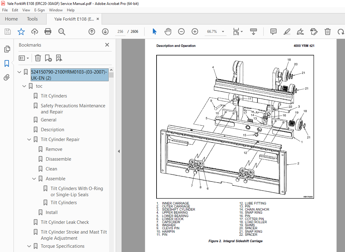
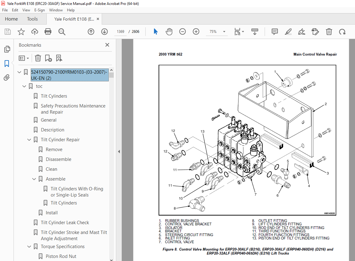
TABLE OF CONTENTS:
Yale Forklift E108 (ERC20-30AGF) Service Manual – PDF DOWNLOAD
524150790-2100YRM0103-(03-2007)-UK-EN (2) 1
toc 1
Tilt Cylinders 1
Safety Precautions Maintenance and Repair 2
General 5
Description 5
Tilt Cylinder Repair 5
Remove 5
Disassemble 5
Clean 5
Assemble 6
Tilt Cylinders With O-Ring or Single-Lip Seals 6
Tilt Cylinders 7
Install 8
Tilt Cylinder Leak Check 10
Tilt Cylinder Stroke and Mast Tilt Angle Adjustment 11
Torque Specifications 11
Piston Rod Nut 11
Retainer 11
Troubleshooting 12
tables 1
Table 1 Movement Rates (Maximum) for Tilt Cylinders 10
524150790-2100YRM0103-(03-2007)-UK-EN 17
toc 17
Tilt Cylinders 17
Safety Precautions Maintenance and Repair 18
General 21
Description 21
Tilt Cylinder Repair 21
Remove 21
Disassemble 21
Clean 21
Assemble 22
Tilt Cylinders With O-Ring or Single-Lip Seals 22
Tilt Cylinders 23
Install 24
Tilt Cylinder Leak Check 26
Tilt Cylinder Stroke and Mast Tilt Angle Adjustment 27
Torque Specifications 27
Piston Rod Nut 27
Retainer 27
Troubleshooting 28
tables 17
Table 1 Movement Rates (Maximum) for Tilt Cylinders 26
524150797-8000YRM0231-(02-2023)-UK-EN 33
General 39
Threaded Fasteners 39
Nomenclature, Threads 39
Strength Identification 40
Cotter (Split) Pins 41
Fastener Torque Tables 46
Conversion Table 48
524150797-8000YRM0231-(03-2020)-UK-EN 55
General 59
Threaded Fasteners 59
Nomenclature, Threads 59
Strength Identification 60
Cotter (Split) Pins 61
Fastener Torque Tables 66
Conversion Table 68
524158040-2240YRM0001-(01-2023)-UK-EN 75
General 81
Battery Type 81
Lead-Acid Batteries 81
Lithium-Ion Batteries 82
Specific Gravity 82
Chemical Reaction in a Cell 82
Electrical Terms 84
Battery Selection 85
Battery Voltage 86
Battery as a Counterweight 86
Battery Ratings 86
Kilowatt-Hours 86
Battery Maintenance 87
Safety Procedures 87
Maintenance Records 87
New Battery 87
Cleaning Battery 88
Adding Water to Battery 90
Hydrometer 90
Battery Temperature 91
Charging Battery 92
Types of Battery Charges 93
Methods of Charging 94
Troubleshooting Charger 95
Knowing When Battery Is Fully Charged 95
Where to Charge Batteries 95
Equipment Needed 95
Battery Connectors 96
Battery Care 96
Troubleshooting 98
524158040-2240YRM0001-(03-2020)-UK-EN 103
General 107
Battery Type 107
Lead-Acid Batteries 107
Lithium-Ion Batteries 108
Specific Gravity 108
Chemical Reaction in a Cell 108
Electrical Terms 110
Battery Selection 110
Battery Voltage 111
Battery as a Counterweight 112
Battery Ratings 112
Kilowatt-Hours 112
Battery Maintenance 112
Safety Procedures 112
Maintenance Records 113
New Battery 113
Cleaning Battery 113
Adding Water to Battery 115
Hydrometer 116
Battery Temperature 117
Charging Battery 118
Types of Battery Charges 118
Methods of Charging 120
Troubleshooting Charger 120
Knowing When Battery Is Fully Charged 121
Where to Charge Batteries 121
Equipment Needed 121
Battery Connectors 122
Battery Care 122
Troubleshooting 124
524158753-1600YRM0720-(11-2006)-UK-EN 129
toc 129
Steering Housing and Control Unit 129
Safety Precautions Maintenance and Repair 130
General 133
Description 133
Operation 134
Steering Wheel and Column Assembly Repair 135
Assembly Components, Remove 135
Steering Control Unit, Disassemble 140
Steering Control Unit, Clean 140
Steering Control Unit, Assemble 140
Assembly Components, Install 142
System Air Removal 144
Troubleshooting 144
524158753-1600YRM0720-(11-2006)-UK-EN_2 149
toc 149
Steering Housing and Control Unit 149
Safety Precautions Maintenance and Repair 150
General 153
Description 153
Operation 154
Steering Wheel and Column Assembly Repair 155
Assembly Components, Remove 155
Steering Control Unit, Disassemble 160
Steering Control Unit, Clean 160
Steering Control Unit, Assemble 160
Assembly Components, Install 162
System Air Removal 164
Troubleshooting 164
524158757-2200YRM0514-(01-2004)-UK-EN (2) 169
toc 169
Instrument Cluster 169
Safety Precautions Maintenance and Repair 170
General 173
Description 173
Instrument Cluster Display Panel, Internal Combustion Lift Truck 173
Instrument Cluster Display Panel, Electric Lift Truck Models 180
Optional Basic Display Panel 180
Features of the Optional Basic Display Panel 180
Description of Features on the Optional Basic Display Panel 180
Standard Display Panel 181
Features of the Standard Display Panel 181
Description of Features on the Standard Display Panel 181
Premium Display Panel 182
Features on the Premium Display Panel 182
Description of Features on the Premium Display Panel 183
Curtis 1215 Display Panel 185
Description and Features 185
Operation 186
Cluster-Type Display Panel (Internal Combustion) Replacement 187
Remove 187
Install 187
Cluster Display Panel (Electric Lift Truck) Replacement 190
Curtis 1215 Display Panel Replacement 195
Remove 195
Install 195
tables 169
Table 1 Instrument Cluster, Internal Combustion 174
524158757-2200YRM0514-(01-2004)-UK-EN 199
toc 199
Instrument Cluster 199
Safety Precautions Maintenance and Repair 200
General 203
Description 203
Instrument Cluster Display Panel, Internal Combustion Lift Truck 203
Instrument Cluster Display Panel, Electric Lift Truck Models 210
Optional Basic Display Panel 210
Features of the Optional Basic Display Panel 210
Description of Features on the Optional Basic Display Panel 210
Standard Display Panel 211
Features of the Standard Display Panel 211
Description of Features on the Standard Display Panel 211
Premium Display Panel 212
Features on the Premium Display Panel 212
Description of Features on the Premium Display Panel 213
Curtis 1215 Display Panel 215
Description and Features 215
Operation 216
Cluster-Type Display Panel (Internal Combustion) Replacement 217
Remove 217
Install 217
Cluster Display Panel (Electric Lift Truck) Replacement 220
Curtis 1215 Display Panel Replacement 225
Remove 225
Install 225
tables 199
Table 1 Instrument Cluster, Internal Combustion 204
524158890-4000YRM0521-(03-2006)-UK-EN (2) 229
toc 229
Mast 229
Safety Precautions Maintenance and Repair 230
General 233
Description and Operation 233
Carriages 233
Mast Mounts 235
Two-Stage Mast, Limited Free-Lift (LFL) 236
Description and Operation 236
Two-Stage Mast, Full Free-Lift (FFL) 238
Description and Operation 238
Three-Stage Mast, Full Free-Lift (FFL) 240
Description and Operation 240
Four-Stage Mast 242
Description and Operation 242
Cylinder Cushion During Lifting Sequence 246
Cylinder Cushion During Lowering Sequence 247
524158890-4000YRM0521-(03-2006)-UK-EN 251
toc 251
Mast 251
Safety Precautions Maintenance and Repair 252
General 255
Description and Operation 255
Carriages 255
Mast Mounts 257
Two-Stage Mast, Limited Free-Lift (LFL) 258
Description and Operation 258
Two-Stage Mast, Full Free-Lift (FFL) 260
Description and Operation 260
Three-Stage Mast, Full Free-Lift (FFL) 262
Description and Operation 262
Four-Stage Mast 264
Description and Operation 264
Cylinder Cushion During Lifting Sequence 268
Cylinder Cushion During Lowering Sequence 269
524158891-4000YRM0522-(07-2010)-UK-EN (2) 273
toc 273
Mast 273
Safety Precautions Maintenance and Repair 274
General 277
Safety Procedures When Working Near Mast 278
Fork Repair 280
Remove 280
Install 280
Carriages Repair 282
Standard Carriage, Remove 282
Hang-On Sideshift Carriage, Remove 283
Standard Carriage and Hang-On Sideshift Carriage, Repair 284
Standard Carriage, Install 285
Hang-On Sideshift Carriage, Install 286
Integral Sideshift Carriage 286
Remove 286
Clean and Inspect 290
Repair 291
Install 292
Mast Repair 293
Remove 293
Two-Stage LFL and Two-Stage FFL Masts, Disassemble 295
Three-Stage FFL Mast 303
Disassemble 303
Mast and Chains, Clean and Inspect 306
Two-Stage LFL and Two-Stage FFL Mast, Assemble 307
Three-Stage FFL Mast, Assemble 308
Install 309
Lift Cylinders Repair 311
Main Lift Cylinders, Remove 311
Free-Lift Cylinder, Remove 311
Cylinders, Disassemble 312
Two-Stage Full Free-Lift Mast, Right-Hand Main Lift Cylinder 312
Two-Stage Full Free-Lift Mast, Left-Hand Main Lift Cylinder 314
Two-Stage Limited Free-Lift Mast and Three-Stage Full Free-Lift 314
Two-Stage Limited Free-Lift Mast and Three-Stage Full Free-Lift 315
Two-Stage Full Free-Lift Mast and Three-Stage Full Free-Lift Mas 316
Clean and Inspect 317
Cylinders, Assemble 317
Two-Stage Full Free-Lift Mast, Right-Hand Main Lift Cylinder 317
Two-Stage Full Free-Lift Mast, Left-Hand Main Lift Cylinder 318
Two-Stage Limited Free-Lift Mast and Three-Stage Full Free-Lift 319
Two-Stage Limited Free-Lift Mast and Three-Stage Full Free-Lift 319
Two-Stage Full Free-Lift Mast and Three-Stage Full Free-Lift Mas 320
Main Lift Cylinders, Install 321
Free-Lift Cylinder, Install 321
Header Hose Arrangements 322
Two-Stage LFL Mast, New Hose Install 322
Two-Stage LFL Mast, Adjust Hoses After Installation 327
Two-Stage FFL Mast, New Hose Install 327
Two-Stage FFL Mast, Adjust Hoses After Installation 335
Three-Stage FFL Mast, New Hose Install 335
Three-Stage FFL Mast, Adjust Hoses After Installation 346
Header Hose Arrangement 347
Two-Stage LFL Mast, New Hose Install 347
Two-Stage LFL Mast, Adjust Hoses After Installation 352
Two-Stage FFL Mast, New Hose Install 352
Two-Stage FFL Mast, Adjust Hoses After Installation 358
Three-Stage FFL Mast, New Hose Install 358
Three-Stage FFL Mast, Adjust Hoses After Install 367
Lift and Tilt System Leak Check 368
Lift Cylinders Leak Check 368
Tilt Cylinders Leak Check 368
Tilt Cylinders Adjustment 369
Lift Chains Adjustment 371
Mast Adjustment 373
Carriage Adjustment 375
Troubleshooting 376
tables 273
Table 1 Hook-Type Carriage Chain Adjustment 371
Table 2 Pin-Type Carriage Chain Adjustment 372
524158891-4000YRM0522-(07-2010)-UK-EN 379
toc 379
Mast 379
Safety Precautions Maintenance and Repair 380
General 383
Safety Procedures When Working Near Mast 384
Fork Repair 386
Remove 386
Install 386
Carriages Repair 388
Standard Carriage, Remove 388
Hang-On Sideshift Carriage, Remove 389
Standard Carriage and Hang-On Sideshift Carriage, Repair 390
Standard Carriage, Install 391
Hang-On Sideshift Carriage, Install 392
Integral Sideshift Carriage 392
Remove 392
Clean and Inspect 396
Repair 397
Install 398
Mast Repair 399
Remove 399
Two-Stage LFL and Two-Stage FFL Masts, Disassemble 401
Three-Stage FFL Mast 409
Disassemble 409
Mast and Chains, Clean and Inspect 412
Two-Stage LFL and Two-Stage FFL Mast, Assemble 413
Three-Stage FFL Mast, Assemble 414
Install 415
Lift Cylinders Repair 417
Main Lift Cylinders, Remove 417
Free-Lift Cylinder, Remove 417
Cylinders, Disassemble 418
Two-Stage Full Free-Lift Mast, Right-Hand Main Lift Cylinder 418
Two-Stage Full Free-Lift Mast, Left-Hand Main Lift Cylinder 420
Two-Stage Limited Free-Lift Mast and Three-Stage Full Free-Lift 420
Two-Stage Limited Free-Lift Mast and Three-Stage Full Free-Lift 421
Two-Stage Full Free-Lift Mast and Three-Stage Full Free-Lift Mas 422
Clean and Inspect 423
Cylinders, Assemble 423
Two-Stage Full Free-Lift Mast, Right-Hand Main Lift Cylinder 423
Two-Stage Full Free-Lift Mast, Left-Hand Main Lift Cylinder 424
Two-Stage Limited Free-Lift Mast and Three-Stage Full Free-Lift 425
Two-Stage Limited Free-Lift Mast and Three-Stage Full Free-Lift 425
Two-Stage Full Free-Lift Mast and Three-Stage Full Free-Lift Mas 426
Main Lift Cylinders, Install 427
Free-Lift Cylinder, Install 427
Header Hose Arrangements 428
Two-Stage LFL Mast, New Hose Install 428
Two-Stage LFL Mast, Adjust Hoses After Installation 433
Two-Stage FFL Mast, New Hose Install 433
Two-Stage FFL Mast, Adjust Hoses After Installation 441
Three-Stage FFL Mast, New Hose Install 441
Three-Stage FFL Mast, Adjust Hoses After Installation 452
Header Hose Arrangement 453
Two-Stage LFL Mast, New Hose Install 453
Two-Stage LFL Mast, Adjust Hoses After Installation 458
Two-Stage FFL Mast, New Hose Install 458
Two-Stage FFL Mast, Adjust Hoses After Installation 464
Three-Stage FFL Mast, New Hose Install 464
Three-Stage FFL Mast, Adjust Hoses After Install 473
Lift and Tilt System Leak Check 474
Lift Cylinders Leak Check 474
Tilt Cylinders Leak Check 474
Tilt Cylinders Adjustment 475
Lift Chains Adjustment 477
Mast Adjustment 479
Carriage Adjustment 481
Troubleshooting 482
tables 379
Table 1 Hook-Type Carriage Chain Adjustment 477
Table 2 Pin-Type Carriage Chain Adjustment 478
524158906-1600YRM0258-(11-2006)-UK-EN 485
General 489
Description 491
Steering Axle Assembly Replacement 492
Remove 492
Install 492
Wheels Repair 493
Remove and Disassemble 493
Clean 493
Inspect 493
Assemble and Install 495
Spindles, Bearings, and Tie Rods Repair 496
Remove and Disassemble 496
Assemble and Install 496
Steering Cylinder Repair 497
Remove and Disassemble 497
Clean and Inspect 498
Assemble and Install 498
Torque Specifications 499
Troubleshooting 500
524166836-1600YRM0485-(07-2003)-UK-EN 503
toc 503
Steering System for Electric Lift Trucks 503
Safety Precautions Maintenance and Repair 504
General 507
Description 509
Steering Wheel and Column Assembly Repair 510
Assembly Components, Remove 510
Assembly Components, Install 514
Power Steering Motor and Pump 515
Description 515
Remove and Disassemble, Models ERC 20-30AGF (ERC040-065RF/ZF, RG 516
Remove and Disassemble, Models ERC35-55HG (ERC70-120HD, ERC70-12 517
Remove and Disassemble, Models ERP20-30ALF 520
Remove and Disassemble, Models ERC/P16-20AAF (ERC040-065AF, AG/B 520
Assemble and Install, All Models With A Vertical Mount Except ER 521
Assemble and Install, Models ERP20-30ALF 521
Assemble and Install, Models ERC/P16-20AAF (ERC030-040AF, AG/BG) 522
Power Steering Pump, Repair 522
Seal, Replace 523
Hydraulic Steering Motor 524
Steering System Air Removal 524
Steering Pressure Check 524
Optical Encoder and Activator Circuits Check 525
Troubleshooting 527
524166836-1600YRM0485-(07-2003)-UK-EN_2 531
toc 531
Steering System for Electric Lift Trucks 531
Safety Precautions Maintenance and Repair 532
General 535
Description 537
Steering Wheel and Column Assembly Repair 538
Assembly Components, Remove 538
Assembly Components, Install 542
Power Steering Motor and Pump 543
Description 543
Remove and Disassemble, Models ERC 20-30AGF (ERC040-065RF/ZF, RG 544
Remove and Disassemble, Models ERC35-55HG (ERC70-120HD, ERC70-12 545
Remove and Disassemble, Models ERP20-30ALF 548
Remove and Disassemble, Models ERC/P16-20AAF (ERC040-065AF, AG/B 548
Assemble and Install, All Models With A Vertical Mount Except ER 549
Assemble and Install, Models ERP20-30ALF 549
Assemble and Install, Models ERC/P16-20AAF (ERC030-040AF, AG/BG) 550
Power Steering Pump, Repair 550
Seal, Replace 551
Hydraulic Steering Motor 552
Steering System Air Removal 552
Steering Pressure Check 552
Optical Encoder and Activator Circuits Check 553
Troubleshooting 555
524166840-2200YRM0560-(07-2005)-UK-EN (2) 559
toc 559
Electrical System 559
Safety Precautions Maintenance and Repair 560
General 565
Description 566
ZX Series Display Panels 566
Optional Basic Display Panel 566
Features of the Optional Basic Display Panel 566
Description of Features on the Optional Basic Display Panel 566
Standard Display Panel 567
Features of the Standard Display Panel 567
Description of Features on the Standard Display Panel 567
Premium Display Panel 568
Features on the Premium Display Panel 568
Description of Features on the Premium Display Panel 569
Curtis 1215 Display Panel 571
Description and Features 571
Operation 571
SEM Display Panels – Features 572
Descriptions of Common Features 573
LED Symbol Indicators – SEM 573
LCD Screen 573
Battery Discharge Indicator (BDI) 573
Service Reminder 574
Status Codes 574
Hourmeter 574
Additional Features of Premium Display Panel 575
Descriptions of Additional Features 575
LCD Screen 575
Operator Passwords 575
Daily Checklist and Service Items 575
Performance Modes 575
Status Code Lists 576
Adjustment of BDI 576
SEM Display Panel Indicators 576
All Indicator Symbols 576
Hourmeter Indicator Symbol 576
Wrench Symbol 576
Battery Symbol 576
Battery Discharge Indicator (BDI) 576
Brake Fluid Too Low Symbol 576
Parking Brake Symbol 576
Fasten Seat Belt Symbol 577
LCD Screen (Standard Display Panel) 577
Additional Components of Premium Display Panel 577
Alpha Numerical Screen 577
STAR Push Button 577
Push Buttons ##1 Through ##5 – SEM 577
Other Control Components 577
Display Panel Components – ZX, and Curtis Replacement 578
ZX Panel Replacement 578
Curtis 1215 Display Panel Replacement 583
Remove 583
Install 583
SEM Display Panel Replacement 584
Motor Controller (SR or SP) Replacement 584
Remove 584
Install 584
Control Components Replacement 586
Start Switch, Replace 586
Brake Light Switch, Replace 587
Seat Switch, Replace 587
External Seat Switch, Adjust 588
Switch for Optional Seat Brake, Replace 589
Parking Brake Switch, Replace 589
Direction Switches Foot Directional Control Replace 590
Direction Control Switches (Steering Column), Replace 591
Direction Control Switches, ERC070-120HG (Steering Column), Repl 592
Brake Fluid Switch, Replace 592
Brush Wear and Overtemperature Sensors 592
Rocker Switches for Lights 593
Accelerator Position Sensor, Replace 593
On-Demand Steering Components 595
Lights, Converter, Relay, and Reverse Alarm 597
Incandescent Brake, Tail, and Reverse Light Assembly, Replace 597
LED Brake, Tail, and Reverse Light Assembly, Replace 599
Remove 599
Install 599
Flashing Light Assembly, Replace 599
Front, Rear Driving Light, or Spot Light Assemblies, Replace 601
Operator Compartment Light Assembly, Replace 601
Converter, Replace 602
Relay, Replace 602
Reverse Alarm, Replace 602
Horn and Horn Button 602
Horn Switch and Cover 603
Hydraulic Pump Switches 603
Control and Power Fuses Check 604
ZX Motor Controllers 604
SEM Motor Controllers 604
SEM Controller Field Diagnostic Procedure 609
Armature FET Test 609
Field FET Test 609
Brush Wear and Overtemperature Sensors Check – ZX Motor Controll 613
Thermal Sensors – SEM Motor Controllers Check 614
Start Switch Adjustment 615
Accelerator Potentiometer and Start Switch, ERC070-120HG Lift Tr 616
ERC070-120HG 616
Direction Switches Foot Directional Control Pedal 617
Brake Light Switch Adjustment 618
Seat Switch Check 619
Optional Seat Brake Switch Adjustment 619
Parking Brake Switch Adjustment 620
Direction Switches Check 620
Foot Directional Control Pedal 620
Steering Column 621
Hydraulic Pump Switch Adjustment 621
Foot Directional Control or Accelerator Pedal Adjustment 621
Accelerator Position Sensor Adjustment 622
524166840-2200YRM0560-(07-2005)-UK-EN 627
toc 627
Electrical System 627
Safety Precautions Maintenance and Repair 628
General 633
Description 634
ZX Series Display Panels 634
Optional Basic Display Panel 634
Features of the Optional Basic Display Panel 634
Description of Features on the Optional Basic Display Panel 634
Standard Display Panel 635
Features of the Standard Display Panel 635
Description of Features on the Standard Display Panel 635
Premium Display Panel 636
Features on the Premium Display Panel 636
Description of Features on the Premium Display Panel 637
Curtis 1215 Display Panel 639
Description and Features 639
Operation 639
SEM Display Panels – Features 640
Descriptions of Common Features 641
LED Symbol Indicators – SEM 641
LCD Screen 641
Battery Discharge Indicator (BDI) 641
Service Reminder 642
Status Codes 642
Hourmeter 642
Additional Features of Premium Display Panel 643
Descriptions of Additional Features 643
LCD Screen 643
Operator Passwords 643
Daily Checklist and Service Items 643
Performance Modes 643
Status Code Lists 644
Adjustment of BDI 644
SEM Display Panel Indicators 644
All Indicator Symbols 644
Hourmeter Indicator Symbol 644
Wrench Symbol 644
Battery Symbol 644
Battery Discharge Indicator (BDI) 644
Brake Fluid Too Low Symbol 644
Parking Brake Symbol 644
Fasten Seat Belt Symbol 645
LCD Screen (Standard Display Panel) 645
Additional Components of Premium Display Panel 645
Alpha Numerical Screen 645
STAR Push Button 645
Push Buttons ##1 Through ##5 – SEM 645
Other Control Components 645
Display Panel Components – ZX, and Curtis Replacement 646
ZX Panel Replacement 646
Curtis 1215 Display Panel Replacement 651
Remove 651
Install 651
SEM Display Panel Replacement 652
Motor Controller (SR or SP) Replacement 652
Remove 652
Install 652
Control Components Replacement 654
Start Switch, Replace 654
Brake Light Switch, Replace 655
Seat Switch, Replace 655
External Seat Switch, Adjust 656
Switch for Optional Seat Brake, Replace 657
Parking Brake Switch, Replace 657
Direction Switches Foot Directional Control Replace 658
Direction Control Switches (Steering Column), Replace 659
Direction Control Switches, ERC070-120HG (Steering Column), Repl 660
Brake Fluid Switch, Replace 660
Brush Wear and Overtemperature Sensors 660
Rocker Switches for Lights 661
Accelerator Position Sensor, Replace 661
On-Demand Steering Components 663
Lights, Converter, Relay, and Reverse Alarm 665
Incandescent Brake, Tail, and Reverse Light Assembly, Replace 665
LED Brake, Tail, and Reverse Light Assembly, Replace 667
Remove 667
Install 667
Flashing Light Assembly, Replace 667
Front, Rear Driving Light, or Spot Light Assemblies, Replace 669
Operator Compartment Light Assembly, Replace 669
Converter, Replace 670
Relay, Replace 670
Reverse Alarm, Replace 670
Horn and Horn Button 670
Horn Switch and Cover 671
Hydraulic Pump Switches 671
Control and Power Fuses Check 672
ZX Motor Controllers 672
SEM Motor Controllers 672
SEM Controller Field Diagnostic Procedure 677
Armature FET Test 677
Field FET Test 677
Brush Wear and Overtemperature Sensors Check – ZX Motor Controll 681
Thermal Sensors – SEM Motor Controllers Check 682
Start Switch Adjustment 683
Accelerator Potentiometer and Start Switch, ERC070-120HG Lift Tr 684
ERC070-120HG 684
Direction Switches Foot Directional Control Pedal 685
Brake Light Switch Adjustment 686
Seat Switch Check 687
Optional Seat Brake Switch Adjustment 687
Parking Brake Switch Adjustment 688
Direction Switches Check 688
Foot Directional Control Pedal 688
Steering Column 689
Hydraulic Pump Switch Adjustment 689
Foot Directional Control or Accelerator Pedal Adjustment 689
Accelerator Position Sensor Adjustment 690
524166842-2200YRM0725-(07-2002)-UK-EN 695
toc 695
SEM Display Panel 695
Safety Precautions Maintenance and Repair 696
General 699
SEM Display Panel Features 699
Common Features Descriptions 699
LED Symbol Indicators 699
LCD Screen 699
Battery Discharge Indicator (BDI) 699
Service Reminder 700
Status Codes 700
Hourmeter 700
Premium Display Panel Additional Features 701
Additional Features Descriptions (Available With Premium Display 701
LCD Screen 701
Operator Passwords 702
Daily Check List and Service Items 702
Performance Modes 702
Status Code Lists 702
BDI, Adjust 702
SEM Display Panel Indicators 703
All Indicator Symbols 703
Hourmeter Indicator Symbol 703
Wrench Indicator Symbol 703
Battery Indicator Symbol 703
Battery State-of-Charge (BDI) 703
Brake Fluid Low Symbol 703
Parking Brake Symbol 703
Fasten Seat Belt Symbol 703
LCD Screen (Standard Display Panel) 703
Premium Display Panel Additional Components 704
Alpha Numerical Screen 704
STAR Push Button 704
Push Buttons ##1 Through ##5 704
Computer Adjustments 704
Computer System 704
Connect PC to SEM Display Panel 705
ITW Switches Software Program (for SEM Display Panel) 705
Description 705
Where to Get Help 706
Hardware and Software Requirements 706
How to Start ITW Switches Program 706
Menus 707
Create a Setup File 712
SEM Display Panel Replacement 729
General 729
Remove and Replace 729
tables 695
Table 1 Adapter Pins (DB25F to DB9) 704
524166844-2200YRM0942-(08-2007)-UK-EN (2) 735
toc 735
Display Panel for SEM Controls 735
Safety Precautions Maintenance and Repair 736
General 739
SEM Display Panel Features 739
Descriptions of Common Features 739
LED Symbol Indicators 739
LCD Screen 739
Battery Discharge Indicator (BDI) 740
Service Reminder 740
Status Codes 740
Hourmeter 740
Additional Features of Premium Display Panel 740
Descriptions of Additional Features (Available With Premium Disp 740
LCD Screen 740
Operator Passwords 741
Daily Check List and Service Items 741
Performance Modes 741
Status Code Lists 741
Adjustment of BDI 741
SEM Display Panel Indicators 742
All Indicator Symbols 742
Hourmeter Indicator Symbol 742
Wrench Indicator Symbol 742
Battery Indicator Symbol 742
Battery State-of-Charge (BDI) 742
Brake Fluid Too Low Symbol 743
Parking Brake Symbol 743
Fasten Seat Belt Symbol 743
LCD Screen (Standard Display Panel) 744
Additional Components of Premium Display Panel 744
Alphanumeric Screen 744
STAR Push Button 744
Push Buttons 1 Through 5 744
Adjustments With a Computer 744
Computer System 744
Connect PC to SEM Display Panel 745
ITW Switches Windows Software Program (for SEM Display Panel) 746
Description 746
Getting Help 746
Hardware and Software Requirements 746
Install 746
How to Start ITW Switches Program 746
Menus 750
Sample Sessions 759
Replacement 781
SEM Display Panel 781
Remove and Replace 781
tables 735
Table 1 Adapter Pins (DB25F to DB9) 745
524166844-2200YRM0942-(08-2007)-UK-EN 787
toc 787
Display Panel for SEM Controls 787
Safety Precautions Maintenance and Repair 788
General 791
SEM Display Panel Features 791
Descriptions of Common Features 791
LED Symbol Indicators 791
LCD Screen 791
Battery Discharge Indicator (BDI) 792
Service Reminder 792
Status Codes 792
Hourmeter 792
Additional Features of Premium Display Panel 792
Descriptions of Additional Features (Available With Premium Disp 792
LCD Screen 792
Operator Passwords 793
Daily Check List and Service Items 793
Performance Modes 793
Status Code Lists 793
Adjustment of BDI 793
SEM Display Panel Indicators 794
All Indicator Symbols 794
Hourmeter Indicator Symbol 794
Wrench Indicator Symbol 794
Battery Indicator Symbol 794
Battery State-of-Charge (BDI) 794
Brake Fluid Too Low Symbol 795
Parking Brake Symbol 795
Fasten Seat Belt Symbol 795
LCD Screen (Standard Display Panel) 796
Additional Components of Premium Display Panel 796
Alphanumeric Screen 796
STAR Push Button 796
Push Buttons 1 Through 5 796
Adjustments With a Computer 796
Computer System 796
Connect PC to SEM Display Panel 797
ITW Switches Windows Software Program (for SEM Display Panel) 798
Description 798
Getting Help 798
Hardware and Software Requirements 798
Install 798
How to Start ITW Switches Program 798
Menus 802
Sample Sessions 811
Replacement 833
SEM Display Panel 833
Remove and Replace 833
tables 787
Table 1 Adapter Pins (DB25F to DB9) 797
524167640-2200YRM0947-(08-2007)-UK-EN (2) 839
toc 839
Troubleshooting and Adjustments With a Computer 839
Safety Precautions Maintenance and Repair 840
Computer System 843
Connect a PC to a Control Card 844
Installation 845
SMARTSET™ Windows Software Program 845
How to Start the Program 845
DEMO Mode 846
Selecting the Communications Port 848
Verification of Controller and Lift Truck 849
Select Lift Truck Series 851
Controller Card Register Parameter List 852
How to Change a Parameter 853
How to Save a Changed Parameter File 854
How to Load a Saved Parameter File 856
How to Show and Remove Saved Parameter Files 856
How to Return to Factory Default Settings 857
How to Save Changes to Control Card 858
How to View Status Codes 859
Saving Status Codes 860
How to Show and Remove Saved Status Code Files 861
Closing and Clearing Status Code List 862
How to View Saved Register Data and Saved Status Data 863
How to Save Register Data and Status Code Data In RTF and TXT 865
GE Sentry™ Software Program 866
Installation 866
Description 866
How to Start GE SENTRY Program 866
How to Reset MIN and MAX Display 871
Graphing Mode 872
How to Exit GE SENTRY Program 873
tables 839
Table 1 Cable Connections – Computer to Control 843
Table 2 Adapter Pins (DB25F to DB9) 844
Table 3 Plug-Z Connection 845
524167640-2200YRM0947-(08-2007)-UK-EN 877
toc 877
Troubleshooting and Adjustments With a Computer 877
Safety Precautions Maintenance and Repair 878
Computer System 881
Connect a PC to a Control Card 882
Installation 883
SMARTSET™ Windows Software Program 883
How to Start the Program 883
DEMO Mode 884
Selecting the Communications Port 886
Verification of Controller and Lift Truck 887
Select Lift Truck Series 889
Controller Card Register Parameter List 890
How to Change a Parameter 891
How to Save a Changed Parameter File 892
How to Load a Saved Parameter File 894
How to Show and Remove Saved Parameter Files 894
How to Return to Factory Default Settings 895
How to Save Changes to Control Card 896
How to View Status Codes 897
Saving Status Codes 898
How to Show and Remove Saved Status Code Files 899
Closing and Clearing Status Code List 900
How to View Saved Register Data and Saved Status Data 901
How to Save Register Data and Status Code Data In RTF and TXT 903
GE Sentry™ Software Program 904
Installation 904
Description 904
How to Start GE SENTRY Program 904
How to Reset MIN and MAX Display 909
Graphing Mode 910
How to Exit GE SENTRY Program 911
tables 877
Table 1 Cable Connections – Computer to Control 881
Table 2 Adapter Pins (DB25F to DB9) 882
Table 3 Plug-Z Connection 883
524179934-0100YRM0558-(11-2007)-UK-EN (2) 915
toc 915
Frame 915
Safety Precautions Maintenance and Repair 916
General 919
Description 919
Main Frame 919
Other Frame Weldments 921
Overhead Guard 921
Overhead Guard Replacement 923
Remove 923
Install 923
Battery and Operator Restraint System, Hood and Seat Brake, and 930
Battery Restraint System 930
Hood 931
Hood With E-Hydraulics 932
Seat Brake 933
Operator Restraint System and Seat Assembly 933
Automatic Locking Retractor (ALR) 933
Emergency Locking Retractor (ELR) 934
Counterweight Replacement 935
Remove 935
Install 936
Traction Motor Replacement 937
Remove 937
Install 939
Hydraulic Tank Repair 940
Inspect 940
Clean 941
Steam Method 941
Chemical Solution 941
Additional Preparations for Repair 942
Small Leaks, Repair 942
Large Leaks, Repair 942
Preparations for Usage After Repair 942
Painting Instructions 942
Safety Label Replacement 944
Battery Specifications 946
tables 915
Table 1 Counterweights 935
Table 2 Lift Truck Models ERC20-30AGF (ERC40-065RF/ZF, ERC40-06 946
Table 3 Lift Truck Models ERC20-30AGF (ERC040-065GH) (A908) 947
524179934-0100YRM0558-(11-2007)-UK-EN 951
toc 951
Frame 951
Safety Precautions Maintenance and Repair 952
General 955
Description 955
Main Frame 955
Other Frame Weldments 957
Overhead Guard 957
Overhead Guard Replacement 959
Remove 959
Install 959
Battery and Operator Restraint System, Hood and Seat Brake, and 966
Battery Restraint System 966
Hood 967
Hood With E-Hydraulics 968
Seat Brake 969
Operator Restraint System and Seat Assembly 969
Automatic Locking Retractor (ALR) 969
Emergency Locking Retractor (ELR) 970
Counterweight Replacement 971
Remove 971
Install 972
Traction Motor Replacement 973
Remove 973
Install 975
Hydraulic Tank Repair 976
Inspect 976
Clean 977
Steam Method 977
Chemical Solution 977
Additional Preparations for Repair 978
Small Leaks, Repair 978
Large Leaks, Repair 978
Preparations for Usage After Repair 978
Painting Instructions 978
Safety Label Replacement 980
Battery Specifications 982
tables 951
Table 1 Counterweights 971
Table 2 Lift Truck Models ERC20-30AGF (ERC40-065RF/ZF, ERC40-06 982
Table 3 Lift Truck Models ERC20-30AGF (ERC040-065GH) (A908) 983
524179937-1400YRM0285-(06-2010)-UK-EN (2) 987
toc 987
Drive Axle, Speed Reducer, and Differential 987
Safety Precautions Maintenance and Repair 988
General 991
Description 991
Drive Axle, Speed Reducer, and Differential Repair 993
Drive Axle, Remove 993
Drive Axle, Disassemble 994
Speed Reducer and Differential, Disassemble 994
Clean 996
Inspect 996
Assemble 997
Speed Reducer and Differential, Assemble 997
Input Gear Assembly, Install 997
New Pinion Assembly, Install 998
Drive Axle, Assemble 1004
Drive Axle Assembly, Install 1004
Torque Specifications 1005
Troubleshooting 1006
tables 987
Table 1 Adjustment of Shims for Pinion Assembly 998
Table 2 Ring and Pinion Tooth Contact Adjustment 1002
524179937-1400YRM0285-(06-2010)-UK-EN 1009
toc 1009
Drive Axle, Speed Reducer, and Differential 1009
Safety Precautions Maintenance and Repair 1010
General 1013
Description 1013
Drive Axle, Speed Reducer, and Differential Repair 1015
Drive Axle, Remove 1015
Drive Axle, Disassemble 1016
Speed Reducer and Differential, Disassemble 1016
Clean 1018
Inspect 1018
Assemble 1019
Speed Reducer and Differential, Assemble 1019
Input Gear Assembly, Install 1019
New Pinion Assembly, Install 1020
Drive Axle, Assemble 1026
Drive Axle Assembly, Install 1026
Torque Specifications 1027
Troubleshooting 1028
tables 1009
Table 1 Adjustment of Shims for Pinion Assembly 1020
Table 2 Ring and Pinion Tooth Contact Adjustment 1024
524179941-1600YRM0512-(07-2003)-UK-EN 1031
toc 1031
Steering Housing and Control Unit 1031
Safety Precautions Maintenance and Repair 1032
General 1035
Description 1035
Operation 1036
Steering Wheel and Column Assembly Repair 1037
Steering Column Assembly, Remove 1037
Steering Control Unit 1042
Disassemble 1042
Clean 1045
Assemble 1046
Install 1053
Steering Column Assembly, Install 1055
System Air Removal 1056
Remove 1056
Troubleshooting 1056
524179941-1600YRM0512-(07-2003)-UK-EN_2 1061
toc 1061
Steering Housing and Control Unit 1061
Safety Precautions Maintenance and Repair 1062
General 1065
Description 1065
Operation 1066
Steering Wheel and Column Assembly Repair 1067
Steering Column Assembly, Remove 1067
Steering Control Unit 1072
Disassemble 1072
Clean 1075
Assemble 1076
Install 1083
Steering Column Assembly, Install 1085
System Air Removal 1086
Remove 1086
Troubleshooting 1086
524179942-1800YRM0574-(04-2008)-UK-EN (2) 1091
toc 1091
Brake System 1091
Safety Precautions Maintenance and Repair 1092
General 1095
Description and Operation 1095
Service Brakes 1095
Master Cylinder 1096
Parking Brake 1097
Service Brakes Repair 1097
Remove and Disassemble 1097
Clean 1101
Inspect 1101
Assemble and Install 1101
Adjust 1104
Parking Brake Repair 1106
Remove and Disassemble 1106
Assemble and Install 1106
Adjust 1107
Master Cylinder Repair 1111
Remove 1111
Disassemble 1112
Clean and Inspect 1114
Assemble 1114
Install 1117
Seat Brake Assembly 1117
Seat Brake, Adjust – Lift Truck Models ERC20-30AGF (ERC040-065RF 1117
Brake Switch, Adjust – Lift Truck Models ERC20-30AGF (ERC040-065 1117
Electric Seat Brake, Adjust for Lift Truck Model ERC20-32AGF (ER 1118
Electric Seat Brake Adjustment With Handle For Lift truck Models 1120
Remove 1120
Clean 1120
Inspect 1120
Install 1122
Adjustments 1122
Solenoid Adjustment 1122
Traction cutoff Switch Adjustment 1122
Cable Adjustment 1124
Service Brakes Adjustment 1126
Brake Pedal Adjustment 1126
Master Cylinder Adjustment 1126
Brake System Air Removal 1126
Parking Brake Not Applied Switch Test 1127
Torque Specifications 1127
Troubleshooting 1127
524179942-1800YRM0574-(04-2008)-UK-EN 1133
toc 1133
Brake System 1133
Safety Precautions Maintenance and Repair 1134
General 1137
Description and Operation 1137
Service Brakes 1137
Master Cylinder 1138
Parking Brake 1139
Service Brakes Repair 1139
Remove and Disassemble 1139
Clean 1143
Inspect 1143
Assemble and Install 1143
Adjust 1146
Parking Brake Repair 1148
Remove and Disassemble 1148
Assemble and Install 1148
Adjust 1149
Master Cylinder Repair 1153
Remove 1153
Disassemble 1154
Clean and Inspect 1156
Assemble 1156
Install 1159
Seat Brake Assembly 1159
Seat Brake, Adjust – Lift Truck Models ERC20-30AGF (ERC040-065RF 1159
Brake Switch, Adjust – Lift Truck Models ERC20-30AGF (ERC040-065 1159
Electric Seat Brake, Adjust for Lift Truck Model ERC20-32AGF (ER 1160
Electric Seat Brake Adjustment With Handle For Lift truck Models 1162
Remove 1162
Clean 1162
Inspect 1162
Install 1164
Adjustments 1164
Solenoid Adjustment 1164
Traction cutoff Switch Adjustment 1164
Cable Adjustment 1166
Service Brakes Adjustment 1168
Brake Pedal Adjustment 1168
Master Cylinder Adjustment 1168
Brake System Air Removal 1168
Parking Brake Not Applied Switch Test 1169
Torque Specifications 1169
Troubleshooting 1169
524179945-1900YRM0559-(04-2009)-UK-EN (2) 1175
toc 1175
Hydraulic System 1175
Safety Precautions Maintenance and Repair 1176
General 1179
Description 1179
Hydraulic System 1179
Operation 1187
Hydraulic System 1187
Hydraulic Gear Pump 1193
Steering Pump 1193
Hydraulic Tank Repair 1201
Tank, Remove [ERC/P16-20AAF (ERC030-040AF, AG/BG) (A814); ERC/P1 1201
Tank, Remove [ERP20-30ALF (B216) and ERP20-30ALF (ERP040-060DH) 1203
Tank, Remove [ERP20-32ALF (ERP040-065DH) (E216)] 1204
Hydraulic Tank [ERC35-55HG (ERC70-120HH) (B839/C839)] 1204
Inspect 1205
Small Leaks, Repair 1206
Large Leaks, Repair 1206
Clean 1206
Steam Method 1206
Chemical Solution Method 1207
Additional Methods for Tank Repair 1207
Tank, Install [ERC/P16-20AAF (ERC030-040AF, AG/BG) (A814); ERC/P 1207
Tank, Install [ERP20-30ALF (B216) and ERP20-30ALF (ERP040-060DH) 1208
Tank, Install [ERP20-32ALF (ERP040-065DH) (E216)] 1208
Filter Replacement 1209
All Lift Trucks Except [ERC35-55HG (ERC70-120HH) (B839/C839); ER 1209
Remove 1209
Install 1210
Lift Truck Models [ERC35-55HG (ERC70-120HH) (B839/C839)] 1210
Remove 1210
Install 1210
Lift truck Models [ERC20-32AGF (ERC040-065GH) (A908) and ERC/P16 1211
Remove 1211
Install 1211
Lift Truck Models [ERP20-32ALF (ERP040-065DH) (E216)] 1213
Remove 1213
Install 1213
Hydraulic Pump Repair 1216
Hydraulic Pump, Remove [ERC/P16-20AAF (ERC030-040AF, AG/BG) (A81 1216
Hydraulic Pump, Disassemble ERC/P16-20AAF (ERC030-040AF, AG/BG) 1216
Inspect 1218
Clean 1218
Pump Seal Replace and Pump Assemble 1218
Assemble Pump on Motor 1218
Hydraulic Pump and Motor, Install [ERC/P16-20AAF (ERC030-040AF, 1220
Hydraulic Pump, Remove [ERP20-30ALF (B216); ERP20-30ALF (ERP040- 1221
Hydraulic Pump, Disassemble [ERC35-55HG (ERC70-120HH) (B839/C839 1222
Hydraulic Pump, Inspect [ERC35-55HG (ERC70-120HH) (B839/C839) an 1224
Hydraulic Pump, Clean [ERC35-55HG (ERC70-120HH) (B839/C839) and 1224
Hydraulic Pump, Assemble [ERC35-55HG (ERC70-120HH) (B839/C839) a 1224
Hydraulic Pump and Motor, Install [ERP20-30ALF (B216); ERP20-30A 1224
Main Control Valve Repair 1226
Steering Pump Repair 1226
Pump, Remove and Disassemble [ERC/P16-20AAF (ERC030-040AF, ERC03 1226
Pump, Remove and Disassemble [ERP20-30ALF (B216); ERP20-30ALF (E 1228
Pump, Assemble and Install 1230
Steering Control Unit Replacement 1231
Remove 1231
Install 1231
Steering Cylinder Repair 1237
Main Control Valve Check and Adjust 1237
Steering Relief Valve Check and Adjust 1238
Specifications 1238
Relief Valve Pressures* 1238
Hydraulic Tank Capacity (dipstick full mark) 1239
Hydraulic Pump Capacities – All Models Except ERC35-55HG (ERC70- 1239
Hydraulic Pump Capacities – Models ERC35-55HG (ERC70-120HH) (B83 1239
Troubleshooting 1239
Steering 1239
Steering Housing and Steering Control Unit 1240
Hydraulic System 1241
524179945-1900YRM0559-(04-2009)-UK-EN 1247
toc 1247
Hydraulic System 1247
Safety Precautions Maintenance and Repair 1248
General 1251
Description 1251
Hydraulic System 1251
Operation 1259
Hydraulic System 1259
Hydraulic Gear Pump 1265
Steering Pump 1265
Hydraulic Tank Repair 1273
Tank, Remove [ERC/P16-20AAF (ERC030-040AF, AG/BG) (A814); ERC/P1 1273
Tank, Remove [ERP20-30ALF (B216) and ERP20-30ALF (ERP040-060DH) 1275
Tank, Remove [ERP20-32ALF (ERP040-065DH) (E216)] 1276
Hydraulic Tank [ERC35-55HG (ERC70-120HH) (B839/C839)] 1276
Inspect 1277
Small Leaks, Repair 1278
Large Leaks, Repair 1278
Clean 1278
Steam Method 1278
Chemical Solution Method 1279
Additional Methods for Tank Repair 1279
Tank, Install [ERC/P16-20AAF (ERC030-040AF, AG/BG) (A814); ERC/P 1279
Tank, Install [ERP20-30ALF (B216) and ERP20-30ALF (ERP040-060DH) 1280
Tank, Install [ERP20-32ALF (ERP040-065DH) (E216)] 1280
Filter Replacement 1281
All Lift Trucks Except [ERC35-55HG (ERC70-120HH) (B839/C839); ER 1281
Remove 1281
Install 1282
Lift Truck Models [ERC35-55HG (ERC70-120HH) (B839/C839)] 1282
Remove 1282
Install 1282
Lift truck Models [ERC20-32AGF (ERC040-065GH) (A908) and ERC/P16 1283
Remove 1283
Install 1283
Lift Truck Models [ERP20-32ALF (ERP040-065DH) (E216)] 1285
Remove 1285
Install 1285
Hydraulic Pump Repair 1288
Hydraulic Pump, Remove [ERC/P16-20AAF (ERC030-040AF, AG/BG) (A81 1288
Hydraulic Pump, Disassemble ERC/P16-20AAF (ERC030-040AF, AG/BG) 1288
Inspect 1290
Clean 1290
Pump Seal Replace and Pump Assemble 1290
Assemble Pump on Motor 1290
Hydraulic Pump and Motor, Install [ERC/P16-20AAF (ERC030-040AF, 1292
Hydraulic Pump, Remove [ERP20-30ALF (B216); ERP20-30ALF (ERP040- 1293
Hydraulic Pump, Disassemble [ERC35-55HG (ERC70-120HH) (B839/C839 1294
Hydraulic Pump, Inspect [ERC35-55HG (ERC70-120HH) (B839/C839) an 1296
Hydraulic Pump, Clean [ERC35-55HG (ERC70-120HH) (B839/C839) and 1296
Hydraulic Pump, Assemble [ERC35-55HG (ERC70-120HH) (B839/C839) a 1296
Hydraulic Pump and Motor, Install [ERP20-30ALF (B216); ERP20-30A 1296
Main Control Valve Repair 1298
Steering Pump Repair 1298
Pump, Remove and Disassemble [ERC/P16-20AAF (ERC030-040AF, ERC03 1298
Pump, Remove and Disassemble [ERP20-30ALF (B216); ERP20-30ALF (E 1300
Pump, Assemble and Install 1302
Steering Control Unit Replacement 1303
Remove 1303
Install 1303
Steering Cylinder Repair 1309
Main Control Valve Check and Adjust 1309
Steering Relief Valve Check and Adjust 1310
Specifications 1310
Relief Valve Pressures* 1310
Hydraulic Tank Capacity (dipstick full mark) 1311
Hydraulic Pump Capacities – All Models Except ERC35-55HG (ERC70- 1311
Hydraulic Pump Capacities – Models ERC35-55HG (ERC70-120HH) (B83 1311
Troubleshooting 1311
Steering 1311
Steering Housing and Steering Control Unit 1312
Hydraulic System 1313
524179946-2000YRM0562-(02-2009)-UK-EN (2) 1319
toc 1319
Manual hydraulic Control Valve 1319
Safety Precautions Maintenance and Repair 1320
General 1323
Description 1323
Operation 1326
ERC/P16-20AAF (ERC030-040AF, AG/BG) (A814); ERC/P16-20AAF (ERC03 1326
ERP20-30ALF (B216), ERP20-30ALF (ERP040-060DH) (D216) and ERP20- 1326
Lift Section 1328
Tilt Section 1328
Tilt Backward 1328
Tilt Forward 1328
Relief Valve 1330
Main Control Valve Repair 1331
Main Control Valve Without OPS Solenoid 1331
Remove 1331
Disassemble 1331
Clean and Inspect 1335
Assemble 1335
Install [ERC/P16-20AAF (ERC030-040AF, AG/BG) (A814); ERC/P16-20A 1336
Install [ERP20-30ALF (B216), ERP20-30ALF (ERP040-060DH) (D216) a 1336
Main Control Valve With OPS Solenoid 1337
Remove 1337
Disassemble 1337
Clean and Inspect 1339
Relief Valve Repair 1341
Assemble 1342
Install 1343
Control Lever Linkage Repair 1343
Remove [ERC/P16-20AAF (ERC030-040AF, AG/BG) (A814),ERC/P16-20AAF 1343
Disassemble [ERC/P16-20AAF (ERC030-040AF, AG/BG) (A814),ERC/P16- 1343
Assemble and Install [ERC/P16-20AAF (ERC030-040AF, AG/BG) (A814) 1345
Control Valve Linkage Repair 1345
Remove and Disassemble [ERC/P16-20AAF (ERC030-040AF, AG/BG) (A81 1345
Assemble and Install [ERC/P16-20AAF (ERC030-040AF, AG/BG) (A814) 1346
Control Lever Linkage Repair 1346
Remove [ERP20-30ALF (B216), ERP20-30ALF (ERP040-060DH) (D216) an 1346
Disassemble [ERP20-30ALF (B216), ERP20-30ALF (ERP040-060DH) (D21 1348
Assemble and Install [ERP20-30ALF (B216), ERP20-30ALF (ERP040-06 1348
Pressure Relief Valve Check and Adjustment 1349
Primary Relief Valve 1349
Secondary Relief Valve 1350
Troubleshooting 1351
524179946-2000YRM0562-(02-2009)-UK-EN 1355
toc 1355
Manual hydraulic Control Valve 1355
Safety Precautions Maintenance and Repair 1356
General 1359
Description 1359
Operation 1362
ERC/P16-20AAF (ERC030-040AF, AG/BG) (A814); ERC/P16-20AAF (ERC03 1362
ERP20-30ALF (B216), ERP20-30ALF (ERP040-060DH) (D216) and ERP20- 1362
Lift Section 1364
Tilt Section 1364
Tilt Backward 1364
Tilt Forward 1364
Relief Valve 1366
Main Control Valve Repair 1367
Main Control Valve Without OPS Solenoid 1367
Remove 1367
Disassemble 1367
Clean and Inspect 1371
Assemble 1371
Install [ERC/P16-20AAF (ERC030-040AF, AG/BG) (A814); ERC/P16-20A 1372
Install [ERP20-30ALF (B216), ERP20-30ALF (ERP040-060DH) (D216) a 1372
Main Control Valve With OPS Solenoid 1373
Remove 1373
Disassemble 1373
Clean and Inspect 1375
Relief Valve Repair 1377
Assemble 1378
Install 1379
Control Lever Linkage Repair 1379
Remove [ERC/P16-20AAF (ERC030-040AF, AG/BG) (A814),ERC/P16-20AAF 1379
Disassemble [ERC/P16-20AAF (ERC030-040AF, AG/BG) (A814),ERC/P16- 1379
Assemble and Install [ERC/P16-20AAF (ERC030-040AF, AG/BG) (A814) 1381
Control Valve Linkage Repair 1381
Remove and Disassemble [ERC/P16-20AAF (ERC030-040AF, AG/BG) (A81 1381
Assemble and Install [ERC/P16-20AAF (ERC030-040AF, AG/BG) (A814) 1382
Control Lever Linkage Repair 1382
Remove [ERP20-30ALF (B216), ERP20-30ALF (ERP040-060DH) (D216) an 1382
Disassemble [ERP20-30ALF (B216), ERP20-30ALF (ERP040-060DH) (D21 1384
Assemble and Install [ERP20-30ALF (B216), ERP20-30ALF (ERP040-06 1384
Pressure Relief Valve Check and Adjustment 1385
Primary Relief Valve 1385
Secondary Relief Valve 1386
Troubleshooting 1387
524179947-2200YRM0557-(07-2003)-UK-EN (2) 1391
toc 1391
EV-100ZX™ SCR Motor Controller 1391
Safety Precautions Maintenance and Repair 1393
General 1399
Model Number Data For EV-100ZX Controller 1400
Register Parameters 1414
General 1414
Function Numbers 1414
Control Card, Checks and Adjustments 1414
Handset 1415
How to Check and Adjust Registers 1415
How to Scroll through Fault Codes and Clear Them 1415
Checks and Adjustments on Workbench 1416
When Handset Is Connected to Control Card Installed In Lift Truc 1417
Function Numbers 1 through 15 1418
Function Numbers 16 through 30 1418
Function Numbers 48 through 62 1418
Control Cards 1419
Function Number Descriptions 1419
Traction Control Cards (Label Letters – ZH and ZY) 1419
Function Number 1 STORED STATUS CODE 1419
Function Number 2 CREEP SPEED 1419
Function Number 3 CONTROLLED ACCELERATION AND 1A TIME 1419
Function Number 4 CURRENT LIMIT 1420
Function Number 5 PLUGGING DISTANCE (CURRENT) 1420
Function Number 6 1A DROP OUT CURRENT 1420
Function Number 7 FIELD WEAKENING PICK UP 1420
Function Number 8 FIELD WEAKENING DROP OUT 1420
Function Number 9 REGENERATIVE BRAKING CURRENT LIMIT 1420
Function Number 10 REGENERATIVE BRAKING START 1421
Function Number 13 SPEED LIMIT 3 (SL3) 1421
Function Number 14 INTERNAL RESISTANCE COMPENSATION 1421
Function Number 15 BATTERY VOLTS 1422
Function Numbers GREATER THAN 15 1422
Function Number 16 PEDAL POSITION PLUG 1422
Function Number 17 CARD TYPE SELECTION 1422
Function Number 18 STEERING PUMP TIME DELAY 1422
Function Number 19 MAINTENANCE ALERT (Tens/Units) 1423
Function Number 20 MAINTENANCE ALERT (Thousands/Hundreds) 1423
Function Number 21 MAINTENANCE SPEED LIMIT 1423
Function Numbers 22 Through 28 TEMPORARY DATA REGISTERS 1423
Function Number 29 HOURMETER (Tens/Units) 1423
Function Number 30 HOURMETER (Thousands/Hundreds) 1423
Function Number 48 Through 62 SET LIFT TRUCK PERFORMANCE 1423
Function Number 48 CONTROLLED ACCELERATION AND 1A TIME 1424
Function Number 49 FIELD WEAKENING PICK UP 1424
Function Number 50 SPEED LIMIT 1 1424
Function Number 52 CONTROLLED ACCELERATION AND 1A TIME 1424
Function Number 53 FIELD WEAKENING PICK UP 1424
Function Number 54 SPEED LIMIT 1 1425
Function Number 56 CONTROLLED ACCELERATION AND 1A TIME 1425
Function Number 57 FIELD WEAKENING PICK UP 1425
Function Number 58 SPEED LIMIT 1 1425
Function Number 60 CONTROLLED ACCELERATION AND 1A TIME 1425
Function Number 61 FIELD WEAKENING PICK UP 1425
Pump Control Card (Label Letter ZP) 1425
Function Number 1 STORED STATUS CODE 1426
Function Number 2 INTERNAL RESISTANCE COMPENSATION START 1426
Function Number 3 CONTROLLED ACCELERATION 1426
Function Number 4 CURRENT LIMIT 1426
Function Number 7 CONTROLLED ACCELERATION COMPENSATION 1426
Function Number 11 SPEED LIMIT 1 (SL1) (Slow Speed) – Tilt and S 1426
Function Number 12 SPEED LIMIT 2 (SL2) (Medium Speed) – Slow Lif 1426
Function Number 13 SPEED LIMIT 3 (SL3) 1426
Function Number 14 SPEED LIMIT 4 (SL4) Fast Lift 1427
Function Numbers Greater Than 15 1427
Function Number 16 INTERNAL RESISTANCE COMPENSATION 1427
Function Number 17 CARD TYPE SELECTION 1427
Function Numbers 18 through 28 TEMPORARY DATA REGISTERS 1427
Function Number 29 HOURMETER (Tens/Units) 1427
Function Number 30 HOURMETER (Thousands/Hundreds) 1427
Function Number 48 CONTROLLED ACCELERATION 1428
Function Number 49 SPEED LIMIT 2 1428
Function Number 50 SPEED LIMIT 3 1428
Function Number 52 CONTROLLED ACCELERATION 1428
Function Number 53 SPEED LIMIT 2 1428
Function Number 54 SPEED LIMIT 3 1428
Function Number 56 CONTROLLED ACCELERATION 1428
Function Number 57 SPEED LIMIT 2 1428
Function Number 58 SPEED LIMIT 3 1428
Function Number 60 CONTROLLED ACCELERATION 1429
Function Number 61 SPEED LIMIT 2 1429
Function Number 62 SPEED LIMIT 3 1429
Register Parameters 1429
Troubleshooting 1429
General 1429
Status Codes 1430
Register Maps 1432
Status Code Charts 1443
EV-100ZX SCR Motor Controller Repair 1484
Fuses 1484
SCR, Check 1484
SCR Assembly 1486
Thermal Protector 1486
SCR 1 Assembly, Replace 1486
OFF Circuit for SCR 1 1487
Reactor Assembly, Check 1487
Suppressors for SCR 2 and SCR 5, Check 1487
SCR 2 and SCR 5, Check 1487
SCR 2 and SCR 5, Replace 1488
Capacitor C1, Check 1488
Diodes D3 and D4 1488
Diodes D3 and D4, Check 1488
Diodes D3 and D4, Replace 1488
Motor Current Sensor 1488
Contactors 1489
Contactor, Repair 1489
Control Card 1491
Control Card Plugs 1492
Brush Wear Indicators 1492
Theory of Operation 1493
Electronic Speed Controls 1493
Silicon Controlled Rectifier (SCR) 1494
Motor Circuit That Operates With Pulses 1495
Traction Circuit 1496
Hydraulic Pump Motor 1496
SCR 1 OFF Circuit 1496
SCR 1 OFF Operation 1497
Induction Current from Motor 1499
Control Cards 1500
Pulse Monitor Trip (PMT) (Traction Circuit Only) 1500
SRO Circuit (Traction Circuit Only) 1500
Sequence of Operation 1501
Control Card Adjustments (Traction Circuit) 1501
Accelerator Control 1505
SCR Control (Hydraulic Pump Motor) 1505
Contactors 1505
Circuit Protection 1506
Traction Circuit Fuse 1506
Current Limit 1506
Thermal Protection 1506
Suppressors 1507
Truck Management Module (TMM1) 1507
Display Panels 1508
Display Panel 1508
Optional Basic Display Panel 1508
Features of the Optional Basic Display Panel 1508
Description of Features on the Optional Basic Display Panel 1509
Standard Display Panel 1509
Features of the Standard Display Panel 1509
Description of Features on the Standard Display Panel 1510
Premium Display Panel 1511
Features on the Premium Display Panel 1511
Description of Features on the Premium Display Panel 1512
Curtis 1215 Display Panel 1514
Description and Features 1514
Operation 1515
tables 1391
Table 1 Terminal and Plug Wire Connections for Control Card ZY, 1406
Table 2 Terminal and Plug Wire Connections for Control Card ZH, 1408
Table 3 Terminal and Plug Wire Connections for Control Card ZH, 1410
Table 4 Terminal and Plug Wire Connections for Controller with 1412
Table 5 Status Codes List 1431
Table 6 Register Map for Control Cards ZH and ZY (Traction) 1433
Table 7 Register Map for Control Card ZP (Hydraulic Pump) 1438
Table 8 Terminal and Plug Wire Connections for TMM1 Module 1508
524179947-2200YRM0557-(07-2003)-UK-EN 1519
toc 1519
EV-100ZX™ SCR Motor Controller 1519
Safety Precautions Maintenance and Repair 1520
General 1525
Model Number Data For EV-100ZX Controller 1526
Register Parameters 1540
General 1540
Function Numbers 1540
Control Card, Checks and Adjustments 1540
Handset 1541
How to Check and Adjust Registers 1541
How to Scroll through Fault Codes and Clear Them 1541
Checks and Adjustments on Workbench 1542
When Handset Is Connected to Control Card Installed In Lift Truc 1543
Function Numbers 1 through 15 1544
Function Numbers 16 through 30 1544
Function Numbers 48 through 62 1544
Control Cards 1545
Function Number Descriptions 1545
Traction Control Cards (Label Letters – ZH and ZY) 1545
Function Number 1 STORED STATUS CODE 1545
Function Number 2 CREEP SPEED 1545
Function Number 3 CONTROLLED ACCELERATION AND 1A TIME 1545
Function Number 4 CURRENT LIMIT 1546
Function Number 5 PLUGGING DISTANCE (CURRENT) 1546
Function Number 6 1A DROP OUT CURRENT 1546
Function Number 7 FIELD WEAKENING PICK UP 1546
Function Number 8 FIELD WEAKENING DROP OUT 1546
Function Number 9 REGENERATIVE BRAKING CURRENT LIMIT 1546
Function Number 10 REGENERATIVE BRAKING START 1547
Function Number 13 SPEED LIMIT 3 (SL3) 1547
Function Number 14 INTERNAL RESISTANCE COMPENSATION 1547
Function Number 15 BATTERY VOLTS 1548
Function Numbers GREATER THAN 15 1548
Function Number 16 PEDAL POSITION PLUG 1548
Function Number 17 CARD TYPE SELECTION 1548
Function Number 18 STEERING PUMP TIME DELAY 1548
Function Number 19 MAINTENANCE ALERT (Tens/Units) 1549
Function Number 20 MAINTENANCE ALERT (Thousands/Hundreds) 1549
Function Number 21 MAINTENANCE SPEED LIMIT 1549
Function Numbers 22 Through 28 TEMPORARY DATA REGISTERS 1549
Function Number 29 HOURMETER (Tens/Units) 1549
Function Number 30 HOURMETER (Thousands/Hundreds) 1549
Function Number 48 Through 62 SET LIFT TRUCK PERFORMANCE 1549
Function Number 48 CONTROLLED ACCELERATION AND 1A TIME 1550
Function Number 49 FIELD WEAKENING PICK UP 1550
Function Number 50 SPEED LIMIT 1 1550
Function Number 52 CONTROLLED ACCELERATION AND 1A TIME 1550
Function Number 53 FIELD WEAKENING PICK UP 1550
Function Number 54 SPEED LIMIT 1 1551
Function Number 56 CONTROLLED ACCELERATION AND 1A TIME 1551
Function Number 57 FIELD WEAKENING PICK UP 1551
Function Number 58 SPEED LIMIT 1 1551
Function Number 60 CONTROLLED ACCELERATION AND 1A TIME 1551
Function Number 61 FIELD WEAKENING PICK UP 1551
Pump Control Card (Label Letter ZP) 1551
Function Number 1 STORED STATUS CODE 1552
Function Number 2 INTERNAL RESISTANCE COMPENSATION START 1552
Function Number 3 CONTROLLED ACCELERATION 1552
Function Number 4 CURRENT LIMIT 1552
Function Number 7 CONTROLLED ACCELERATION COMPENSATION 1552
Function Number 11 SPEED LIMIT 1 (SL1) (Slow Speed) – Tilt and S 1552
Function Number 12 SPEED LIMIT 2 (SL2) (Medium Speed) – Slow Lif 1552
Function Number 13 SPEED LIMIT 3 (SL3) 1552
Function Number 14 SPEED LIMIT 4 (SL4) Fast Lift 1553
Function Numbers Greater Than 15 1553
Function Number 16 INTERNAL RESISTANCE COMPENSATION 1553
Function Number 17 CARD TYPE SELECTION 1553
Function Numbers 18 through 28 TEMPORARY DATA REGISTERS 1553
Function Number 29 HOURMETER (Tens/Units) 1553
Function Number 30 HOURMETER (Thousands/Hundreds) 1553
Function Number 48 CONTROLLED ACCELERATION 1554
Function Number 49 SPEED LIMIT 2 1554
Function Number 50 SPEED LIMIT 3 1554
Function Number 52 CONTROLLED ACCELERATION 1554
Function Number 53 SPEED LIMIT 2 1554
Function Number 54 SPEED LIMIT 3 1554
Function Number 56 CONTROLLED ACCELERATION 1554
Function Number 57 SPEED LIMIT 2 1554
Function Number 58 SPEED LIMIT 3 1554
Function Number 60 CONTROLLED ACCELERATION 1555
Function Number 61 SPEED LIMIT 2 1555
Function Number 62 SPEED LIMIT 3 1555
Register Parameters 1555
Troubleshooting 1555
General 1555
Status Codes 1556
Register Maps 1558
Status Code Charts 1569
EV-100ZX SCR Motor Controller Repair 1610
Fuses 1610
SCR, Check 1610
SCR Assembly 1612
Thermal Protector 1612
SCR 1 Assembly, Replace 1612
OFF Circuit for SCR 1 1613
Reactor Assembly, Check 1613
Suppressors for SCR 2 and SCR 5, Check 1613
SCR 2 and SCR 5, Check 1613
SCR 2 and SCR 5, Replace 1614
Capacitor C1, Check 1614
Diodes D3 and D4 1614
Diodes D3 and D4, Check 1614
Diodes D3 and D4, Replace 1614
Motor Current Sensor 1614
Contactors 1615
Contactor, Repair 1615
Control Card 1617
Control Card Plugs 1618
Brush Wear Indicators 1618
Theory of Operation 1619
Electronic Speed Controls 1619
Silicon Controlled Rectifier (SCR) 1620
Motor Circuit That Operates With Pulses 1621
Traction Circuit 1622
Hydraulic Pump Motor 1622
SCR 1 OFF Circuit 1622
SCR 1 OFF Operation 1623
Induction Current from Motor 1625
Control Cards 1626
Pulse Monitor Trip (PMT) (Traction Circuit Only) 1626
SRO Circuit (Traction Circuit Only) 1626
Sequence of Operation 1627
Control Card Adjustments (Traction Circuit) 1627
Accelerator Control 1631
SCR Control (Hydraulic Pump Motor) 1631
Contactors 1631
Circuit Protection 1632
Traction Circuit Fuse 1632
Current Limit 1632
Thermal Protection 1632
Suppressors 1633
Truck Management Module (TMM1) 1633
Display Panels 1634
Display Panel 1634
Optional Basic Display Panel 1634
Features of the Optional Basic Display Panel 1634
Description of Features on the Optional Basic Display Panel 1635
Standard Display Panel 1635
Features of the Standard Display Panel 1635
Description of Features on the Standard Display Panel 1636
Premium Display Panel 1637
Features on the Premium Display Panel 1637
Description of Features on the Premium Display Panel 1638
Curtis 1215 Display Panel 1640
Description and Features 1640
Operation 1641
tables 1519
Table 1 Terminal and Plug Wire Connections for Control Card ZY, 1532
Table 2 Terminal and Plug Wire Connections for Control Card ZH, 1534
Table 3 Terminal and Plug Wire Connections for Control Card ZH, 1536
Table 4 Terminal and Plug Wire Connections for Controller with 1538
Table 5 Status Codes List 1557
Table 6 Register Map for Control Cards ZH and ZY (Traction) 1559
Table 7 Register Map for Control Card ZP (Hydraulic Pump) 1564
Table 8 Terminal and Plug Wire Connections for TMM1 Module 1634
524179949-2200YRM0595-(07-2003)-UK-EN (2) 1645
toc 1645
EV-100ZX™ SCR Motor Controller 1645
Safety Precautions Maintenance and Repair 1646
Register Parameters 1649
General 1649
Function Numbers 1649
Control Card Checks and Adjustments 1650
Register Parameter Tables 1650
tables 1645
Table 1 EV-100ZX Parameters – ERC040-065RF/ZF, and ERP20-30ALF 1651
Table 2 EV-100ZX Parameters – ERC040-065RF/ZF (36 to 48V) (Trac 1655
Table 3 EV-100ZX Parameters – ERC20-30AGF, and ERP20-30ALF (72 1659
Table 4 EV-100ZX Parameters – ERC20-30AGF (72 to 80V) (Traction 1663
Table 5 EV-100ZX Parameters – ERC20-30AGF (72 to 80V) (Low Ener 1667
Table 6 EV-100ZX Parameters – ERC70-120HD, ERC040-065RF/ZF, and 1671
Table 7 EV-100ZX Parameters – ERC35-55HG, ERC20-30AGF, and ERP2 1675
524179949-2200YRM0595-(07-2003)-UK-EN 1681
toc 1681
EV-100ZX™ SCR Motor Controller 1681
Safety Precautions Maintenance and Repair 1682
Register Parameters 1685
General 1685
Function Numbers 1685
Control Card Checks and Adjustments 1686
Register Parameter Tables 1686
tables 1681
Table 1 EV-100ZX Parameters – ERC040-065RF/ZF, and ERP20-30ALF 1687
Table 2 EV-100ZX Parameters – ERC040-065RF/ZF (36 to 48V) (Trac 1691
Table 3 EV-100ZX Parameters – ERC20-30AGF, and ERP20-30ALF (72 1695
Table 4 EV-100ZX Parameters – ERC20-30AGF (72 to 80V) (Traction 1699
Table 5 EV-100ZX Parameters – ERC20-30AGF (72 to 80V) (Low Ener 1703
Table 6 EV-100ZX Parameters – ERC70-120HD, ERC040-065RF/ZF, and 1707
Table 7 EV-100ZX Parameters – ERC35-55HG, ERC20-30AGF, and ERP2 1711
524179951-2200YRM0724-(04-2005)-UK-EN (2) 1717
toc 1717
SR/SP Transistor Motor Controllers 1717
Safety Precautions Maintenance and Repair 1718
Description 1723
General 1723
Model Number Data for SR/SP Transistor Motor Controllers 1724
Motor Controller Checks and Adjustments 1727
Checks and Adjustments Using Handset 1727
General 1727
Connect Handset 1728
Start Sequence 1728
Check or Delete Stored Status Codes 1729
Returning Lift Truck to Normal Operation 1731
Workbench Checks and Adjustments 1731
How to Check and Adjust Registers 1733
Function Parameters Adjustments 1733
General 1733
Function Numbers 1734
When Handset is Connected to Motor Controller in Lift Truck 1734
Function Numbers 1 through 15 1734
Function Numbers 16 through 30 1734
Function Numbers 48 through 63 1735
Function Number Descriptions 1736
Traction Motor Controller (Label Letter – SR) 1736
Function Number 01 AUTO REGEN ENABLE SPEED 1736
Function Number 02 CREEP SPEED 1736
Function Number 03 CONTROLLED ACCELERATION 1736
Function Number 04 ARMATURE CURRENT LIMIT 1736
Function Number 05 REGEN RAMP RATE 1737
Function Number 06 FIELD WEAKENING (FW) RATIO 1737
Function Number 07 MINIMUM FIELD CURRENT 1737
Function Number 08 MAXIMUM FIELD CURRENT 1737
Function Number 09 REGENERATIVE BRAKING CURRENT LIMIT (C/L) 1737
Function Number 10 FIELD CURRENT FOR REGENERATIVE BRAKING 1737
Function Number 12 MAXIMUM ARMATURE % ON TIME (Travel Speed Limi 1737
Function Number 13 SPEED LIMIT 3 1738
Function Number 14 INTERNAL RESISTANCE COMPENSATION 1738
Function Number 15 BATTERY VOLTAGE SELECTION 1738
Function Number 16 STALL TRIP POINT % ON TIME 1739
Function Number 17 CONTROL TYPE SELECTION 1739
Function Number 18 STEERING PUMP TIME DELAY 1739
Function Number 19 MAINTENANCE CODE TENS AND UNITS 1740
Function Number 20 MAINTENANCE CODE THOUSANDS AND HUNDREDS 1740
Function Number 21 AUTO REGEN BRAKING CURRENT LIMIT 1740
Function Number 23 FOR SPECIAL FUNCTIONS 1740
Function Number 24 FIELD WEAKENING START 1740
Function Number 25 MONITOR 1740
Function Number 26 BASE RATIO 1740
Function Number 28 STORED STATUS CODE COUNT POINTER 1740
Functions with Premium Display Panel Only 1741
Function Number 48 MODE 1 – CONTROLLED ACCELERATION 1741
Function Number 49 MODE 1 FIELD WEAKENING (FW) START 1741
Function Number 50 MODE 1 – FIELD WEAKENING (FW) RATIO 1741
Function 51 MODE 1 – MAXIMUM ARMATURE % ON TIME (MODE 1 – TRAVEL 1742
Function 52 MODE 2 – CONTROLLED ACCELERATION 1742
Function Number 53 MODE 2 – FIELD WEAKENING (FW) START 1742
Function Number 54 MODE 2 – FIELD WEAKENING (FW) RATIO 1742
Function Number 55 MODE 2 – MAXIMUM ARMATURE % ON TIME (MODE 2 – 1742
Function Number 56 MODE 3 – CONTROLLED ACCELERATION 1742
Function Number 57 MODE 3 – FIELD WEAKENING (FW) START 1742
Function Number 58 MODE 3 – FIELD WEAKENING (FW) RATIO 1742
Function Number 59 MODE 3 – MAXIMUM ARMATURE % ON TIME (MODE 3 – 1743
Function Number 60 MODE 4 – CONTROLLED ACCELERATION 1743
Function Number 61 MODE 4 – FIELD WEAKENING (FW) START 1743
Function Number 62 MODE 4 – FIELD WEAKENING (FW) RATIO 1743
Function Number 63 MODE 4 – MAXIMUM ARMATURE % ON TIME (MODE 4 – 1743
Pump Motor Controller (Label Letter – SP) 1743
Function Number 01 STORED STATUS CODE 1743
Function Number 02 INTERNAL RESISTANCE COMPENSATION START 1744
Function Number 03 CONTROLLED ACCELERATION 1744
Function Number 04 CURRENT LIMIT 1744
Function Number 07 INTERNAL RESISTANCE COMPENSATION RATE 1744
Function Number 11 SPEED LIMIT 1 (SL1) (Slow Speed) – Tilt and S 1744
Function Number 12 SPEED LIMIT 2 (SL2) (Medium Speed) – Slow Lif 1744
Function Number 13 SPEED LIMIT 3 (SL3) Fast Lift 1744
Function Number 16 SPEED/TORQUE COMPENSATION 1745
Function Number 17 CONTROL TYPE SELECTION 1745
Function Numbers 18 through 27 TEMPORARY DATA REGISTERS 1745
Function Number 28 STORED STATUS CODE COUNT POINTER 1745
Functions with Premium Display Panel Only 1745
Function Number 48 MODE 1 – CONTROLLED ACCELERATION 1746
Function Number 49 MODE 1 – SPEED LIMIT 2 1746
Function Number 50 MODE 1 – SPEED LIMIT 3 1746
Function Number 52 MODE 2 – CONTROLLED ACCELERATION 1746
Function Number 53 MODE 2 – SPEED LIMIT 2 1746
Function Number 54 MODE 2 – SPEED LIMIT 3 1746
Function Number 56 MODE 3 – CONTROLLED ACCELERATION 1746
Function Number 57 MODE 3 – SPEED LIMIT 2 1746
Function Number 58 MODE 3 – SPEED LIMIT 3 1747
Function Number 60 MODE 4 – CONTROLLED ACCELERATION 1747
Function Number 61 MODE 4 – SPEED LIMIT 2 1747
Function Number 62 MODE 4 – SPEED LIMIT 3 1747
Troubleshooting 1751
General 1751
Status Codes 1752
SR (SEM) and SP Status Code Charts 1754
SR/SP Transistor Motor Controller Repair 1788
General 1788
General Maintenance Instructions 1788
Special Precautions 1791
Fuses 1791
Contactors 1792
Repair 1792
Contactor Driver Module 1794
Contactor Driver, Replace 1794
Motor Controller Plug 1794
Brush Wear Indicators 1799
Thermal Sensors 1799
Motor Controller, Replace 1799
Theory of Operation 1800
General 1800
SEM System Description 1800
SEM System Operation (SR Motor Controller) 1800
Reverse Circuit 1800
Performance and Efficiency 1802
Field Weakening 1802
Regenerative Braking 1802
SEM System Operation (SP Motor Controller) 1803
Creep Speed 1803
Controlled Acceleration 1803
Current Limit (CL) 1803
Braking 1803
Regenerative Braking to Zero Speed 1803
Pedal Position Braking 1804
Auto Braking 1804
Auxiliary Speed Control 1804
Field Weakening 1804
Speed Limits 1804
Ramp Operation 1804
Ramp Start 1804
Anti-rollback 1804
Steer Pump Contactor Time Delay 1804
Coil Drivers and Internal Coil Suppression 1804
System Protective Override 1804
Static Return to Off (SRO) 1804
Accelerator Volts Hold Off 1805
Pulse Monitor Trip (PMT) 1805
Thermal Protector (TP) 1805
Low Voltage 1805
SP Pump Motor Controllers 1805
Contactor Driver Module 1806
Diagnostics 1806
Systems Diagnostics 1806
Standard Status Codes 1806
Stored Status Codes 1806
Hourmeter Readings 1806
Maintenance Management Capability 1806
tables 1717
Table 1 List of Status Codes 1730
Table 2 Speed/Torque Compensation 1744
Table 3 Function Map for Motor Controllers SR (Traction) 1747
Table 4 Function Map for Motor Controller SP (Lift Pump Motor) 1750
Table 5 List of Status Codes 1752
Table 6 Large (P) Plug (23-Pin) Connections/Descriptions for Mo 1795
Table 7 Small Plug (12-Pin) Connections/Descriptions for Motor 1796
524179951-2200YRM0724-(04-2005)-UK-EN 1809
toc 1809
SR/SP Transistor Motor Controllers 1809
Safety Precautions Maintenance and Repair 1810
Description 1815
General 1815
Model Number Data for SR/SP Transistor Motor Controllers 1816
Motor Controller Checks and Adjustments 1819
Checks and Adjustments Using Handset 1819
General 1819
Connect Handset 1820
Start Sequence 1820
Check or Delete Stored Status Codes 1821
Returning Lift Truck to Normal Operation 1823
Workbench Checks and Adjustments 1823
How to Check and Adjust Registers 1825
Function Parameters Adjustments 1825
General 1825
Function Numbers 1826
When Handset is Connected to Motor Controller in Lift Truck 1826
Function Numbers 1 through 15 1826
Function Numbers 16 through 30 1826
Function Numbers 48 through 63 1827
Function Number Descriptions 1828
Traction Motor Controller (Label Letter – SR) 1828
Function Number 01 AUTO REGEN ENABLE SPEED 1828
Function Number 02 CREEP SPEED 1828
Function Number 03 CONTROLLED ACCELERATION 1828
Function Number 04 ARMATURE CURRENT LIMIT 1828
Function Number 05 REGEN RAMP RATE 1829
Function Number 06 FIELD WEAKENING (FW) RATIO 1829
Function Number 07 MINIMUM FIELD CURRENT 1829
Function Number 08 MAXIMUM FIELD CURRENT 1829
Function Number 09 REGENERATIVE BRAKING CURRENT LIMIT (C/L) 1829
Function Number 10 FIELD CURRENT FOR REGENERATIVE BRAKING 1829
Function Number 12 MAXIMUM ARMATURE % ON TIME (Travel Speed Limi 1829
Function Number 13 SPEED LIMIT 3 1830
Function Number 14 INTERNAL RESISTANCE COMPENSATION 1830
Function Number 15 BATTERY VOLTAGE SELECTION 1830
Function Number 16 STALL TRIP POINT % ON TIME 1831
Function Number 17 CONTROL TYPE SELECTION 1831
Function Number 18 STEERING PUMP TIME DELAY 1831
Function Number 19 MAINTENANCE CODE TENS AND UNITS 1832
Function Number 20 MAINTENANCE CODE THOUSANDS AND HUNDREDS 1832
Function Number 21 AUTO REGEN BRAKING CURRENT LIMIT 1832
Function Number 23 FOR SPECIAL FUNCTIONS 1832
Function Number 24 FIELD WEAKENING START 1832
Function Number 25 MONITOR 1832
Function Number 26 BASE RATIO 1832
Function Number 28 STORED STATUS CODE COUNT POINTER 1832
Functions with Premium Display Panel Only 1833
Function Number 48 MODE 1 – CONTROLLED ACCELERATION 1833
Function Number 49 MODE 1 FIELD WEAKENING (FW) START 1833
Function Number 50 MODE 1 – FIELD WEAKENING (FW) RATIO 1833
Function 51 MODE 1 – MAXIMUM ARMATURE % ON TIME (MODE 1 – TRAVEL 1834
Function 52 MODE 2 – CONTROLLED ACCELERATION 1834
Function Number 53 MODE 2 – FIELD WEAKENING (FW) START 1834
Function Number 54 MODE 2 – FIELD WEAKENING (FW) RATIO 1834
Function Number 55 MODE 2 – MAXIMUM ARMATURE % ON TIME (MODE 2 – 1834
Function Number 56 MODE 3 – CONTROLLED ACCELERATION 1834
Function Number 57 MODE 3 – FIELD WEAKENING (FW) START 1834
Function Number 58 MODE 3 – FIELD WEAKENING (FW) RATIO 1834
Function Number 59 MODE 3 – MAXIMUM ARMATURE % ON TIME (MODE 3 – 1835
Function Number 60 MODE 4 – CONTROLLED ACCELERATION 1835
Function Number 61 MODE 4 – FIELD WEAKENING (FW) START 1835
Function Number 62 MODE 4 – FIELD WEAKENING (FW) RATIO 1835
Function Number 63 MODE 4 – MAXIMUM ARMATURE % ON TIME (MODE 4 – 1835
Pump Motor Controller (Label Letter – SP) 1835
Function Number 01 STORED STATUS CODE 1835
Function Number 02 INTERNAL RESISTANCE COMPENSATION START 1836
Function Number 03 CONTROLLED ACCELERATION 1836
Function Number 04 CURRENT LIMIT 1836
Function Number 07 INTERNAL RESISTANCE COMPENSATION RATE 1836
Function Number 11 SPEED LIMIT 1 (SL1) (Slow Speed) – Tilt and S 1836
Function Number 12 SPEED LIMIT 2 (SL2) (Medium Speed) – Slow Lif 1836
Function Number 13 SPEED LIMIT 3 (SL3) Fast Lift 1836
Function Number 16 SPEED/TORQUE COMPENSATION 1837
Function Number 17 CONTROL TYPE SELECTION 1837
Function Numbers 18 through 27 TEMPORARY DATA REGISTERS 1837
Function Number 28 STORED STATUS CODE COUNT POINTER 1837
Functions with Premium Display Panel Only 1837
Function Number 48 MODE 1 – CONTROLLED ACCELERATION 1838
Function Number 49 MODE 1 – SPEED LIMIT 2 1838
Function Number 50 MODE 1 – SPEED LIMIT 3 1838
Function Number 52 MODE 2 – CONTROLLED ACCELERATION 1838
Function Number 53 MODE 2 – SPEED LIMIT 2 1838
Function Number 54 MODE 2 – SPEED LIMIT 3 1838
Function Number 56 MODE 3 – CONTROLLED ACCELERATION 1838
Function Number 57 MODE 3 – SPEED LIMIT 2 1838
Function Number 58 MODE 3 – SPEED LIMIT 3 1839
Function Number 60 MODE 4 – CONTROLLED ACCELERATION 1839
Function Number 61 MODE 4 – SPEED LIMIT 2 1839
Function Number 62 MODE 4 – SPEED LIMIT 3 1839
Troubleshooting 1843
General 1843
Status Codes 1844
SR (SEM) and SP Status Code Charts 1846
SR/SP Transistor Motor Controller Repair 1880
General 1880
General Maintenance Instructions 1880
Special Precautions 1883
Fuses 1883
Contactors 1884
Repair 1884
Contactor Driver Module 1886
Contactor Driver, Replace 1886
Motor Controller Plug 1886
Brush Wear Indicators 1891
Thermal Sensors 1891
Motor Controller, Replace 1891
Theory of Operation 1892
General 1892
SEM System Description 1892
SEM System Operation (SR Motor Controller) 1892
Reverse Circuit 1892
Performance and Efficiency 1894
Field Weakening 1894
Regenerative Braking 1894
SEM System Operation (SP Motor Controller) 1895
Creep Speed 1895
Controlled Acceleration 1895
Current Limit (CL) 1895
Braking 1895
Regenerative Braking to Zero Speed 1895
Pedal Position Braking 1896
Auto Braking 1896
Auxiliary Speed Control 1896
Field Weakening 1896
Speed Limits 1896
Ramp Operation 1896
Ramp Start 1896
Anti-rollback 1896
Steer Pump Contactor Time Delay 1896
Coil Drivers and Internal Coil Suppression 1896
System Protective Override 1896
Static Return to Off (SRO) 1896
Accelerator Volts Hold Off 1897
Pulse Monitor Trip (PMT) 1897
Thermal Protector (TP) 1897
Low Voltage 1897
SP Pump Motor Controllers 1897
Contactor Driver Module 1898
Diagnostics 1898
Systems Diagnostics 1898
Standard Status Codes 1898
Stored Status Codes 1898
Hourmeter Readings 1898
Maintenance Management Capability 1898
tables 1809
Table 1 List of Status Codes 1822
Table 2 Speed/Torque Compensation 1836
Table 3 Function Map for Motor Controllers SR (Traction) 1839
Table 4 Function Map for Motor Controller SP (Lift Pump Motor) 1842
Table 5 List of Status Codes 1844
Table 6 Large (P) Plug (23-Pin) Connections/Descriptions for Mo 1887
Table 7 Small Plug (12-Pin) Connections/Descriptions for Motor 1888
524179952-2200YRM0739-(04-2005)-UK-EN (2) 1901
toc 1901
Transistor Motor Controllers 1901
Safety Precautions Maintenance and Repair 1902
General 1905
Function Numbers 1905
Motor Controller Checks and Adjustments 1906
Parameter Tables 1906
tables 1901
Table 1 SR (SEM) Register Parameters for Traction Motor Control 1906
Table 2 SR (SEM) Register Parameters for Traction Motor Control 1910
Table 3 SP Register Parameters for Pump Motor Controller – ERC/ 1913
Table 4 SR (SEM) Register Parameters for Traction Motor Control 1916
Table 5 SR (SEM) Register Parameters for Traction Motor Control 1920
Table 6 SR (SEM) Register Parameters for Traction Motor Control 1923
Table 7 SR (SEM) Register Parameters for Traction Motor Control 1927
Table 8 SP Register Parameters for Pump Motor Controller – ERC0 1930
Table 9 SP Register Parameters for Pump Motor Controller – ERC2 1933
Table 10 SR (SEM) Register Parameters for Traction Motor Contro 1937
Table 11 SR (SEM) Register Parameters for Traction Motor Contro 1940
Table 12 SR (SEM) Register Parameters for Traction Motor Contro 1943
Table 13 SP Register Parameters for Pump Motor Controller – ERP 1946
Table 14 SP Register Parameters for Pump Motor Controller – ERP 1949
524179952-2200YRM0739-(04-2005)-UK-EN 1955
toc 1955
Transistor Motor Controllers 1955
Safety Precautions Maintenance and Repair 1956
General 1959
Function Numbers 1959
Motor Controller Checks and Adjustments 1960
Parameter Tables 1960
tables 1955
Table 1 SR (SEM) Register Parameters for Traction Motor Control 1960
Table 2 SR (SEM) Register Parameters for Traction Motor Control 1964
Table 3 SP Register Parameters for Pump Motor Controller – ERC/ 1967
Table 4 SR (SEM) Register Parameters for Traction Motor Control 1970
Table 5 SR (SEM) Register Parameters for Traction Motor Control 1974
Table 6 SR (SEM) Register Parameters for Traction Motor Control 1977
Table 7 SR (SEM) Register Parameters for Traction Motor Control 1981
Table 8 SP Register Parameters for Pump Motor Controller – ERC0 1984
Table 9 SP Register Parameters for Pump Motor Controller – ERC2 1987
Table 10 SR (SEM) Register Parameters for Traction Motor Contro 1991
Table 11 SR (SEM) Register Parameters for Traction Motor Contro 1994
Table 12 SR (SEM) Register Parameters for Traction Motor Contro 1997
Table 13 SP Register Parameters for Pump Motor Controller – ERP 2000
Table 14 SP Register Parameters for Pump Motor Controller – ERP 2003
524179953-4000YRM0563-(04-2005)-UK-EN (2) 2009
toc 2009
Four-Stage Mast 2009
Safety Precautions Maintenance and Repair 2010
General 2013
Description 2013
Carriages 2013
Mast Mounts 2014
Mast 2014
Description 2014
Operation 2015
Forks Repair 2018
Remove 2018
Install 2018
Safety Procedures When Working Near Mast 2020
Carriage Repair 2022
Remove 2022
Standard Carriage 2022
Sideshift Carriage 2023
Repairs 2024
Install 2024
Standard Carriage 2024
Sideshift Carriage 2024
Mast Repair 2025
Remove 2025
Disassemble 2025
Clean and Inspect 2026
Assemble 2027
Install 2029
Lift Cylinders Repair 2032
Remove 2032
Main Lift Cylinders 2032
Free-Lift Cylinders 2032
Disassemble 2032
Assemble 2034
Install 2036
Main Lift Cylinder 2036
Free-Lift Cylinder 2037
Header Hose Arrangements 2038
Header Hoses, Install 2038
Lift and Tilt System Leaks Check 2045
Lift Cylinders Leaks Check 2045
Tilt Cylinders Leaks Check 2045
Tilt Cylinders Adjustment 2046
Lift Chain Adjustments 2047
Mast Adjustments 2048
Carriage Adjustments 2050
Troubleshooting 2051
tables 2009
Table 1 Standard Four-Stage Hose Dimensions 2044
Table 2 Hook type Carriage Chain Adjustment 2047
Table 3 Pin-Type Carriage Chain Adjustment 2048
524179953-4000YRM0563-(04-2005)-UK-EN 2055
toc 2055
Four-Stage Mast 2055
Safety Precautions Maintenance and Repair 2056
General 2059
Description 2059
Carriages 2059
Mast Mounts 2060
Mast 2060
Description 2060
Operation 2061
Forks Repair 2064
Remove 2064
Install 2064
Safety Procedures When Working Near Mast 2066
Carriage Repair 2068
Remove 2068
Standard Carriage 2068
Sideshift Carriage 2069
Repairs 2070
Install 2070
Standard Carriage 2070
Sideshift Carriage 2070
Mast Repair 2071
Remove 2071
Disassemble 2071
Clean and Inspect 2072
Assemble 2073
Install 2075
Lift Cylinders Repair 2078
Remove 2078
Main Lift Cylinders 2078
Free-Lift Cylinders 2078
Disassemble 2078
Assemble 2080
Install 2082
Main Lift Cylinder 2082
Free-Lift Cylinder 2083
Header Hose Arrangements 2084
Header Hoses, Install 2084
Lift and Tilt System Leaks Check 2091
Lift Cylinders Leaks Check 2091
Tilt Cylinders Leaks Check 2091
Tilt Cylinders Adjustment 2092
Lift Chain Adjustments 2093
Mast Adjustments 2094
Carriage Adjustments 2096
Troubleshooting 2097
tables 2055
Table 1 Standard Four-Stage Hose Dimensions 2090
Table 2 Hook type Carriage Chain Adjustment 2093
Table 3 Pin-Type Carriage Chain Adjustment 2094
524179954-8000YRM0551-(07-2003)-UK-EN (2) 2101
toc 2101
Electrical Diagrams 2101
Safety Precautions Maintenance and Repair 2102
524179954-8000YRM0551-(07-2003)-UK-EN 2171
toc 2171
Electrical Diagrams 2171
Safety Precautions Maintenance and Repair 2172
524179956-8000YRM0742-(06-2004)-UK-EN (2) 2241
toc 2241
Electrical Diagrams 2241
Safety Precautions Maintenance and Repair 2242
524179956-8000YRM0742-(06-2004)-UK-EN 2305
toc 2305
Electrical Diagrams 2305
Safety Precautions Maintenance and Repair 2306
524179957-8000YRM0552-(07-2003)-UK-EN (2) 2369
toc 2369
Periodic Maintenance 2369
Safety Precautions Maintenance and Repair 2371
General 2377
Serial Number Data 2377
How to Move Disabled Lift Truck 2377
How to Tow Lift Truck 2377
How to Put Lift Truck on Blocks 2378
How to Raise Drive Tires 2378
How to Raise Steering Tires 2378
Maintenance Schedule 2379
Maintenance Procedures Every 8 Hours or Daily 2386
How to Make Checks With Key OFF 2386
Tires and Wheels 2386
Forks 2387
Adjust 2387
Remove 2388
Install 2388
Forks, Mast, and Lift Chains, Inspect 2388
Safety Labels 2389
Steering Column Latch 2389
Operator Restraint System 2389
Battery Restraint System ERC/P16-20AAF (ERC030-040AF – AG/BG), E 2390
Battery Restraint System ERP20-30ALF 2391
Battery 2392
Hydraulic System 2393
How to Make Checks With Key ON 2393
Gauges, Horn, and Fuses 2393
Steering System 2394
Service Brakes 2394
Parking Brake 2394
Control Levers and Pedals 2394
Direction and Speed Control Pedals 2394
Lift System Operation 2395
Maintenance Procedures Every 250 Hours or 6 Weeks 2395
Steering Tie Rods 2395
Maintenance Procedures Every 500 Hours or 3 Months 2396
Hydraulic Tank Breather 2396
Differential and Speed Reducer 2396
Wheel Nut Torques 2397
Steering Axle Spindles 2397
Steering Tie Rods 2397
Mast 2397
Lift Chains 2398
Wear Check 2398
Forks 2399
Brake Fluid 2399
Other Lubrication 2399
Seat Brake, ERC/P16-20AAF (ERC030-040AF – AG/BG), ERC20-30AGF (E 2400
Electrical Inspection 2400
Contactors 2400
Motor Brushes 2405
Motor Brushes, General 2405
Maintenance Procedures Every 1000 Hours or 6 Months 2413
Lift Chains 2413
Forks 2413
Check Upper and Lower Bearings, Integral Sideshift Carriage 2413
Maintenance Procedures Every 2000 Hours or Yearly 2414
Hydraulic System 2414
Change Filter for Hydraulic Oil 2414
Change Hydraulic Oil 2415
Differential and Speed Reducer 2415
Service Brakes 2415
Contactors 2416
Wheel Bearings 2416
Steer Wheels, Lubrication 2416
Drive Wheels, Lubrication 2416
Lift Chains 2416
Replace Upper and Lower Bearings, Integral Sideshift Carriage 2416
Steering Axle 2417
King Pins and Rod Ends (Steering Cylinders) 2417
Other Lubrication 2417
Battery Maintenance 2417
How to Charge Battery 2417
How to Change Battery 2418
General 2418
Change Battery, ERC/P16-20AAF (ERC030-040AF – AG/BG) and ERC20-3 2419
Change ERP20-30ALF Battery 2422
Lift and Tilt System Leak Check 2424
Lift Cylinders Leak Check 2424
Tilt Cylinders Leak Check 2424
Safety Procedures When Working Near Mast 2425
Lift Chain Adjustments 2427
PMT Circuit Check 2429
Welding Repairs 2430
Overhead Guard Changes 2430
Wheels and Tire Maintenance 2430
Tires and Wheels, ERC/P16-20AAF (ERC030-040AF – AG/BG), ERC20-30 2430
Remove Wheels From Lift Truck 2431
Remove and Install Tire on Wheel 2431
Pneumatic Tires and Wheels ERP20-30ALF 2431
Remove Wheels From Lift Truck 2431
Remove Wheel From Pneumatic Tire 2432
Install Wheel in Pneumatic Tire 2433
Install Three- or Four-Piece Wheel in Pneumatic Tire 2434
Add Air to Tires 2435
Wheels, Install 2436
Solid Rubber Tires on Pneumatic Wheels 2436
Remove Wheels From Lift Truck 2436
Remove Solid Rubber Tire From Pneumatic Wheel 2436
Install Solid Rubber Tire on Pneumatic Wheel 2438
Wheels, Install 2439
SIT Tire, Change 2439
Remove SIT Solid Tire From Wheel 2440
Install SIT Solid Tire on Wheel 2441
Adhesives and Sealants 2442
tables 2369
Table 1 Maintenance Schedule 2381
Table 2 Hook-Type Carriage Chain Adjustment 2428
Table 3 Pin-Type Carriage Chain Adjustment 2428
524179957-8000YRM0552-(07-2003)-UK-EN 2445
toc 2445
Periodic Maintenance 2445
Safety Precautions Maintenance and Repair 2446
General 2451
Serial Number Data 2451
How to Move Disabled Lift Truck 2451
How to Tow Lift Truck 2451
How to Put Lift Truck on Blocks 2452
How to Raise Drive Tires 2452
How to Raise Steering Tires 2452
Maintenance Schedule 2453
Maintenance Procedures Every 8 Hours or Daily 2460
How to Make Checks With Key OFF 2460
Tires and Wheels 2460
Forks 2461
Adjust 2461
Remove 2462
Install 2462
Forks, Mast, and Lift Chains, Inspect 2462
Safety Labels 2463
Steering Column Latch 2463
Operator Restraint System 2463
Battery Restraint System ERC/P16-20AAF (ERC030-040AF – AG/BG), E 2464
Battery Restraint System ERP20-30ALF 2465
Battery 2466
Hydraulic System 2467
How to Make Checks With Key ON 2467
Gauges, Horn, and Fuses 2467
Steering System 2468
Service Brakes 2468
Parking Brake 2468
Control Levers and Pedals 2468
Direction and Speed Control Pedals 2468
Lift System Operation 2469
Maintenance Procedures Every 250 Hours or 6 Weeks 2469
Steering Tie Rods 2469
Maintenance Procedures Every 500 Hours or 3 Months 2470
Hydraulic Tank Breather 2470
Differential and Speed Reducer 2470
Wheel Nut Torques 2471
Steering Axle Spindles 2471
Steering Tie Rods 2471
Mast 2471
Lift Chains 2472
Wear Check 2472
Forks 2473
Brake Fluid 2473
Other Lubrication 2473
Seat Brake, ERC/P16-20AAF (ERC030-040AF – AG/BG), ERC20-30AGF (E 2474
Electrical Inspection 2474
Contactors 2474
Motor Brushes 2479
Motor Brushes, General 2479
Maintenance Procedures Every 1000 Hours or 6 Months 2487
Lift Chains 2487
Forks 2487
Check Upper and Lower Bearings, Integral Sideshift Carriage 2487
Maintenance Procedures Every 2000 Hours or Yearly 2488
Hydraulic System 2488
Change Filter for Hydraulic Oil 2488
Change Hydraulic Oil 2489
Differential and Speed Reducer 2489
Service Brakes 2489
Contactors 2490
Wheel Bearings 2490
Steer Wheels, Lubrication 2490
Drive Wheels, Lubrication 2490
Lift Chains 2490
Replace Upper and Lower Bearings, Integral Sideshift Carriage 2490
Steering Axle 2491
King Pins and Rod Ends (Steering Cylinders) 2491
Other Lubrication 2491
Battery Maintenance 2491
How to Charge Battery 2491
How to Change Battery 2492
General 2492
Change Battery, ERC/P16-20AAF (ERC030-040AF – AG/BG) and ERC20-3 2493
Change ERP20-30ALF Battery 2496
Lift and Tilt System Leak Check 2498
Lift Cylinders Leak Check 2498
Tilt Cylinders Leak Check 2498
Safety Procedures When Working Near Mast 2499
Lift Chain Adjustments 2501
PMT Circuit Check 2503
Welding Repairs 2504
Overhead Guard Changes 2504
Wheels and Tire Maintenance 2504
Tires and Wheels, ERC/P16-20AAF (ERC030-040AF – AG/BG), ERC20-30 2504
Remove Wheels From Lift Truck 2505
Remove and Install Tire on Wheel 2505
Pneumatic Tires and Wheels ERP20-30ALF 2505
Remove Wheels From Lift Truck 2505
Remove Wheel From Pneumatic Tire 2506
Install Wheel in Pneumatic Tire 2507
Install Three- or Four-Piece Wheel in Pneumatic Tire 2508
Add Air to Tires 2509
Wheels, Install 2510
Solid Rubber Tires on Pneumatic Wheels 2510
Remove Wheels From Lift Truck 2510
Remove Solid Rubber Tire From Pneumatic Wheel 2510
Install Solid Rubber Tire on Pneumatic Wheel 2512
Wheels, Install 2513
SIT Tire, Change 2513
Remove SIT Solid Tire From Wheel 2514
Install SIT Solid Tire on Wheel 2515
Adhesives and Sealants 2516
tables 2445
Table 1 Maintenance Schedule 2455
Table 2 Hook-Type Carriage Chain Adjustment 2502
Table 3 Pin-Type Carriage Chain Adjustment 2502
524179958-8000YRM0561-(07-2003)-UK-EN (2) 2519
toc 2519
Capacities and Specifications 2519
Safety Precautions Maintenance and Repair 2520
Counterweights 2523
Hydraulic System 2523
Wheels and Tires 2524
Battery Specifications 2525
ERC20-30ALF 2525
ERC20-30AGF (ERC040-065RG/ZG, RF/ZF) 2526
Capacities 2527
Movement Rates (Maximum) for Tilt Cylinders 2527
Mast Speeds 2528
ERC20-30ALF Mast Speeds (72 or 80 Volt) Europe 2528
ERC20-30ALF Mast Speeds (72 or 80 Volt) Europe 2533
ERC040-065RG/ZG (36 or 48 Volt) Americas 2536
ERC040-065RG/ZG Mast Speeds (36 or 48 Volt) Americas 2540
ERC20-30AGF Mast Speeds (72 or 80 Volt) Europe 2543
Torque Specifications 2551
Frame 2551
Drive Axle, Speed Reducer, and Differential ERC20-30ALF 2551
Drive Axle, Speed Reducer, and Differential ERC20-30AGF (ERC040R 2552
Steering Axle ERC20-30ALF 2552
Steering Axle ERC20-30AGF (ERC040-065RG/ZG, RF/ZF) 2552
Masts 2552
Seat Brake 2553
Adhesives and Sealants 2553
524179958-8000YRM0561-(07-2003)-UK-EN 2557
toc 2557
Capacities and Specifications 2557
Safety Precautions Maintenance and Repair 2558
Counterweights 2561
Hydraulic System 2561
Wheels and Tires 2562
Battery Specifications 2563
ERC20-30ALF 2563
ERC20-30AGF (ERC040-065RG/ZG, RF/ZF) 2564
Capacities 2565
Movement Rates (Maximum) for Tilt Cylinders 2565
Mast Speeds 2566
ERC20-30ALF Mast Speeds (72 or 80 Volt) Europe 2566
ERC20-30ALF Mast Speeds (72 or 80 Volt) Europe 2571
ERC040-065RG/ZG (36 or 48 Volt) Americas 2574
ERC040-065RG/ZG Mast Speeds (36 or 48 Volt) Americas 2578
ERC20-30AGF Mast Speeds (72 or 80 Volt) Europe 2581
Torque Specifications 2589
Frame 2589
Drive Axle, Speed Reducer, and Differential ERC20-30ALF 2589
Drive Axle, Speed Reducer, and Differential ERC20-30AGF (ERC040R 2590
Steering Axle ERC20-30ALF 2590
Steering Axle ERC20-30AGF (ERC040-065RG/ZG, RF/ZF) 2590
Masts 2590
Seat Brake 2591
Adhesives and Sealants 2591
524270787-2200YRM0597-(03-2006)-UK-EN 2595
toc 2595
Troubleshooting and Adjustments With a Computer 2595
Safety Precautions Maintenance and Repair 2596
Computer System 2599
Connect PC to Control Card 2600
GE Sentry Software® 2601
Getting Started 2601
Where to Get Help 2601
Hardware and Software Requirements 2601
GE SENTRY SOFTWARE Installation 2602
How to Start GE SENTRY Program 2602
How to Reset MIN and MAX Display 2603
How to Exit GE SENTRY Program 2603
tables 2595
Table 1 Cable Connections – Computer to Control 2599
Table 2 Adapter Pins (DB25F to DB9) 2599
Table 3 Plug-Z Connection 2601
More products