$40.95
Yale Forklift E216 (ERP040, 050, 060, 065DH) Service Manual PDF
Yale Forklift E216 (ERP040, 050, 060, 065DH) Service Manual – PDF DOWNLOAD
FILE DETAILS:
Yale Forklift E216 (ERP040, 050, 060, 065DH) Service Manual – PDF DOWNLOAD
Language : English
Pages : 1056
Downloadable : Yes
File Type : PDF
IMAGES PREVIEW OF THE MANUAL:
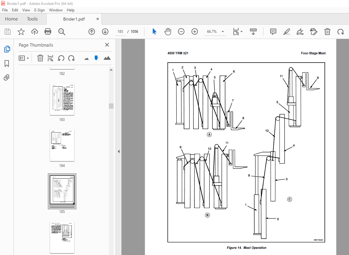
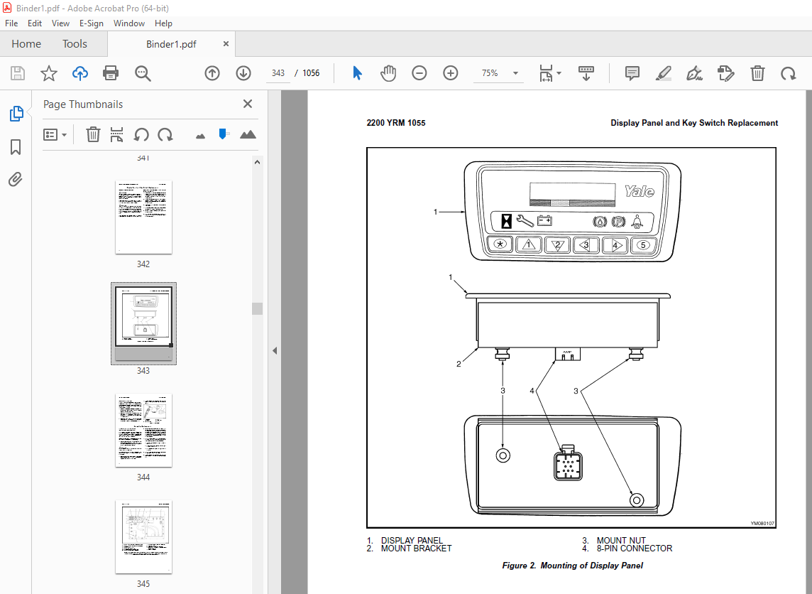
TABLE OF CONTENTS:
Yale Forklift E216 (ERP040, 050, 060, 065DH) Service Manual – PDF DOWNLOAD
524150797-8000YRM0231-(02-2023)-UK-EN 1
General 7
Threaded Fasteners 7
Nomenclature, Threads 7
Strength Identification 8
Cotter (Split) Pins 9
Fastener Torque Tables 14
Conversion Table 16
524150797-8000YRM0231-(03-2020)-UK-EN 23
General 27
Threaded Fasteners 27
Nomenclature, Threads 27
Strength Identification 28
Cotter (Split) Pins 29
Fastener Torque Tables 34
Conversion Table 36
524158039-0620YRM0294-(09-2016)-UK-EN 43
General 47
Brush and Commutator Inspection 48
Hydraulic Pump Motor and Traction Motor 48
Steering Pump Motor 51
Normal Commutator Surface 51
Commutator Problems 51
Brush Replacement 56
Stoning the Commutator 59
Motors Repair 60
Disassemble 61
Traction Motor and Hydraulic Pump Motor 61
Steering Pump Motor 62
Assemble 66
Traction Motor and Hydraulic Pump Motor 66
Steering Pump Motor 68
Brush Alignment, Traction and Hydraulic Motors 70
Tests for Damaged Field and Armature 71
Test for an Open Circuit in One Armature Winding 71
Test for Short Circuit in One Armature Winding 71
Test for Short Circuit to Armature Shaft 72
Test for Open Circuit in Field Coil 72
Test for Short Circuit in Field Coil 73
Test for Short Circuit Between Field and Motor Case 73
Brush Holder Test 73
Troubleshooting 74
524158040-2240YRM0001-(01-2023)-UK-EN 79
General 85
Battery Type 85
Lead-Acid Batteries 85
Lithium-Ion Batteries 86
Specific Gravity 86
Chemical Reaction in a Cell 86
Electrical Terms 88
Battery Selection 89
Battery Voltage 90
Battery as a Counterweight 90
Battery Ratings 90
Kilowatt-Hours 90
Battery Maintenance 91
Safety Procedures 91
Maintenance Records 91
New Battery 91
Cleaning Battery 92
Adding Water to Battery 94
Hydrometer 94
Battery Temperature 95
Charging Battery 96
Types of Battery Charges 97
Methods of Charging 98
Troubleshooting Charger 99
Knowing When Battery Is Fully Charged 99
Where to Charge Batteries 99
Equipment Needed 99
Battery Connectors 100
Battery Care 100
Troubleshooting 102
524158040-2240YRM0001-(03-2020)-UK-EN 107
General 111
Battery Type 111
Lead-Acid Batteries 111
Lithium-Ion Batteries 112
Specific Gravity 112
Chemical Reaction in a Cell 112
Electrical Terms 114
Battery Selection 114
Battery Voltage 115
Battery as a Counterweight 116
Battery Ratings 116
Kilowatt-Hours 116
Battery Maintenance 116
Safety Procedures 116
Maintenance Records 117
New Battery 117
Cleaning Battery 117
Adding Water to Battery 119
Hydrometer 120
Battery Temperature 121
Charging Battery 122
Types of Battery Charges 122
Methods of Charging 124
Troubleshooting Charger 124
Knowing When Battery Is Fully Charged 125
Where to Charge Batteries 125
Equipment Needed 125
Battery Connectors 126
Battery Care 126
Troubleshooting 128
524158752-1600YRM0316-(08-2006)-UK-EN 133
toc 133
Steering Axle 133
Safety Precautions Maintenance and Repair 134
General 137
Description 137
Steering Axle Assembly Repair 138
Remove 138
Install 138
Wheels and Hubs Repair 139
Remove and Disassemble 139
Clean 139
Assemble and Install 139
Spindles, Bearings, and Tie Rods Repair 141
Remove 141
Install 141
Steering Cylinder Repair 142
Remove and Disassemble 142
Clean and Inspect 143
Assemble and Install 143
Torque Specifications 143
Troubleshooting 144
524158753-1600YRM0720-(11-2006)-UK-EN 149
toc 149
Steering Housing and Control Unit 149
Safety Precautions Maintenance and Repair 150
General 153
Description 153
Operation 154
Steering Wheel and Column Assembly Repair 155
Assembly Components, Remove 155
Steering Control Unit, Disassemble 160
Steering Control Unit, Clean 160
Steering Control Unit, Assemble 160
Assembly Components, Install 162
System Air Removal 164
Troubleshooting 164
524158890-4000YRM0521-(03-2006)-UK-EN 169
toc 169
Mast 169
Safety Precautions Maintenance and Repair 170
General 173
Description and Operation 173
Carriages 173
Mast Mounts 175
Two-Stage Mast, Limited Free-Lift (LFL) 176
Description and Operation 176
Two-Stage Mast, Full Free-Lift (FFL) 178
Description and Operation 178
Three-Stage Mast, Full Free-Lift (FFL) 180
Description and Operation 180
Four-Stage Mast 182
Description and Operation 182
Cylinder Cushion During Lifting Sequence 186
Cylinder Cushion During Lowering Sequence 187
524179945-1900YRM0559-(04-2009)-UK-EN 191
toc 191
Hydraulic System 191
Safety Precautions Maintenance and Repair 192
General 195
Description 195
Hydraulic System 195
Operation 203
Hydraulic System 203
Hydraulic Gear Pump 209
Steering Pump 209
Hydraulic Tank Repair 217
Tank, Remove [ERC/P16-20AAF (ERC030-040AF, AG/BG) (A814); ERC/P1 217
Tank, Remove [ERP20-30ALF (B216) and ERP20-30ALF (ERP040-060DH) 219
Tank, Remove [ERP20-32ALF (ERP040-065DH) (E216)] 220
Hydraulic Tank [ERC35-55HG (ERC70-120HH) (B839/C839)] 220
Inspect 221
Small Leaks, Repair 222
Large Leaks, Repair 222
Clean 222
Steam Method 222
Chemical Solution Method 223
Additional Methods for Tank Repair 223
Tank, Install [ERC/P16-20AAF (ERC030-040AF, AG/BG) (A814); ERC/P 223
Tank, Install [ERP20-30ALF (B216) and ERP20-30ALF (ERP040-060DH) 224
Tank, Install [ERP20-32ALF (ERP040-065DH) (E216)] 224
Filter Replacement 225
All Lift Trucks Except [ERC35-55HG (ERC70-120HH) (B839/C839); ER 225
Remove 225
Install 226
Lift Truck Models [ERC35-55HG (ERC70-120HH) (B839/C839)] 226
Remove 226
Install 226
Lift truck Models [ERC20-32AGF (ERC040-065GH) (A908) and ERC/P16 227
Remove 227
Install 227
Lift Truck Models [ERP20-32ALF (ERP040-065DH) (E216)] 229
Remove 229
Install 229
Hydraulic Pump Repair 232
Hydraulic Pump, Remove [ERC/P16-20AAF (ERC030-040AF, AG/BG) (A81 232
Hydraulic Pump, Disassemble ERC/P16-20AAF (ERC030-040AF, AG/BG) 232
Inspect 234
Clean 234
Pump Seal Replace and Pump Assemble 234
Assemble Pump on Motor 234
Hydraulic Pump and Motor, Install [ERC/P16-20AAF (ERC030-040AF, 236
Hydraulic Pump, Remove [ERP20-30ALF (B216); ERP20-30ALF (ERP040- 237
Hydraulic Pump, Disassemble [ERC35-55HG (ERC70-120HH) (B839/C839 238
Hydraulic Pump, Inspect [ERC35-55HG (ERC70-120HH) (B839/C839) an 240
Hydraulic Pump, Clean [ERC35-55HG (ERC70-120HH) (B839/C839) and 240
Hydraulic Pump, Assemble [ERC35-55HG (ERC70-120HH) (B839/C839) a 240
Hydraulic Pump and Motor, Install [ERP20-30ALF (B216); ERP20-30A 240
Main Control Valve Repair 242
Steering Pump Repair 242
Pump, Remove and Disassemble [ERC/P16-20AAF (ERC030-040AF, ERC03 242
Pump, Remove and Disassemble [ERP20-30ALF (B216); ERP20-30ALF (E 244
Pump, Assemble and Install 246
Steering Control Unit Replacement 247
Remove 247
Install 247
Steering Cylinder Repair 253
Main Control Valve Check and Adjust 253
Steering Relief Valve Check and Adjust 254
Specifications 254
Relief Valve Pressures* 254
Hydraulic Tank Capacity (dipstick full mark) 255
Hydraulic Pump Capacities – All Models Except ERC35-55HG (ERC70- 255
Hydraulic Pump Capacities – Models ERC35-55HG (ERC70-120HH) (B83 255
Troubleshooting 255
Steering 255
Steering Housing and Steering Control Unit 256
Hydraulic System 257
524179946-2000YRM0562-(02-2009)-UK-EN 263
toc 263
Manual hydraulic Control Valve 263
Safety Precautions Maintenance and Repair 264
General 267
Description 267
Operation 270
ERC/P16-20AAF (ERC030-040AF, AG/BG) (A814); ERC/P16-20AAF (ERC03 270
ERP20-30ALF (B216), ERP20-30ALF (ERP040-060DH) (D216) and ERP20- 270
Lift Section 272
Tilt Section 272
Tilt Backward 272
Tilt Forward 272
Relief Valve 274
Main Control Valve Repair 275
Main Control Valve Without OPS Solenoid 275
Remove 275
Disassemble 275
Clean and Inspect 279
Assemble 279
Install [ERC/P16-20AAF (ERC030-040AF, AG/BG) (A814); ERC/P16-20A 280
Install [ERP20-30ALF (B216), ERP20-30ALF (ERP040-060DH) (D216) a 280
Main Control Valve With OPS Solenoid 281
Remove 281
Disassemble 281
Clean and Inspect 283
Relief Valve Repair 285
Assemble 286
Install 287
Control Lever Linkage Repair 287
Remove [ERC/P16-20AAF (ERC030-040AF, AG/BG) (A814),ERC/P16-20AAF 287
Disassemble [ERC/P16-20AAF (ERC030-040AF, AG/BG) (A814),ERC/P16- 287
Assemble and Install [ERC/P16-20AAF (ERC030-040AF, AG/BG) (A814) 289
Control Valve Linkage Repair 289
Remove and Disassemble [ERC/P16-20AAF (ERC030-040AF, AG/BG) (A81 289
Assemble and Install [ERC/P16-20AAF (ERC030-040AF, AG/BG) (A814) 290
Control Lever Linkage Repair 290
Remove [ERP20-30ALF (B216), ERP20-30ALF (ERP040-060DH) (D216) an 290
Disassemble [ERP20-30ALF (B216), ERP20-30ALF (ERP040-060DH) (D21 292
Assemble and Install [ERP20-30ALF (B216), ERP20-30ALF (ERP040-06 292
Pressure Relief Valve Check and Adjustment 293
Primary Relief Valve 293
Secondary Relief Valve 294
Troubleshooting 295
524183080-0620YRM1053-(03-2010)-UK-EN 299
toc 299
AC Motor Repair 299
Safety Precautions Maintenance and Repair 300
General 303
AC Motor Repair 304
Disassemble 304
Assemble 306
Drive End Bearing, Replace 307
Disassemble, ERP20-32ALF (ERP040-065DH) (E216) Traction Motor 307
Assemble, ERP20-32ALF (ERP040-065DH) (E216) Traction Motor 309
Troubleshooting 310
524183081-1600YRM1054-(11-2006)-UK-EN 313
toc 313
Steering System for AC Electric Lift Trucks 313
Safety Precautions Maintenance and Repair 314
General 317
Description 318
Steering Wheel and Column Assembly Repair 319
General 319
Assembly Components, Remove 321
Assembly Components, Install 322
Power Steering Motor and Pump 323
Description 323
Remove 323
Disassemble 326
Install 326
Power Steering Pump, Repair 326
Seal, Replace 327
Steering System Air Removal 328
Steering Pressure Check 328
Steering Motor Circuits Check 329
Troubleshooting 330
524183082-2200YRM1055-(10-2009)-UK-EN 335
toc 335
Electrical System (Trucks With AC Controllers) 335
Safety Precautions Maintenance and Repair 336
General 339
Description 340
Features of the Display Panels 340
Other Control Components 341
Display Panel and Key Switch Replacement 342
Display Panel, Replace 342
Key Switch, Replace 344
Controller Replacement 344
Traction and Pump Motor Controller Replacement 344
Master Controller, Replace 350
Master Controller, Remove ERP20-30ALF (ERP040-060DH) (D216), ERP 350
Master Controller, Install ERP20-30ALF (ERP040-060DH) (D216), ER 350
Master Controller, Remove ERC/P16-20AAF (ERC030-040AH) (B814/C81 352
Master Controller, Install ERC/P16-20AAF (ERC030-040AH) (B814/C8 352
Master Controller, Remove ERC35-55HG (ERC070-120HH) (B839/C839) 354
Master Controller, Install ERC35-55HG (ERC070-120HH) (B839/C839) 354
Control Components Replacement 355
General 355
Start Switch, Replace 355
Brake Light Switch, Replace 356
Seat Switch, Replace 356
Parking Brake Switch, Replace 357
Foot Directional Control Pedal Direction Switches, Replace 359
Steering Column Direction Control Switches, Replace 362
Remove 362
Install 362
Brake Fluid Switch, Replace 364
Brush Wear and Over Temperature Sensors (DC Pump Motor Only) 364
Rocker Switches for Lights, Replace 364
Accelerator Position Sensor, Replace 365
On-Demand Steering Sensor, Replace 366
Lights, Converter, Relay, and Reverse Alarm 366
Brake, Tail, and Reverse Light Assembly, Replace 367
Incandescent Assembly 367
LED Assembly – Remove 369
LED Assembly – Install 369
Strobe Light Assembly, Replace 372
Wire Harness Repair 373
Del-City Crimp-Solder-Shrink Splice 373
Front, Rear Driving Light or Spot Light Assemblies, Replace 374
Converter, Replace 374
Remove, Lift Truck Models ERP20-30ALF (ERP040-060DH) (D216), ERP 374
Install, Lift Truck Models ERP20-30ALF (ERP040-060DH) (D216), ER 376
Remove, Lift Truck Models ERC20-32AGF (ERC040-065GH) (A908) and 376
Install, Lift Truck Models ERC20-32AGF (ERC040-065GH) (A908) and 376
Remove, Lift Truck Models ERC35-55HG (ERC70-120HH) (B839/C839) 378
Install, Lift Truck Models ERC35-55HG (ERC70-120HH) (B839/C839) 378
Reverse Relay, Replace 379
Lift Truck Models ERC20-32AGF (ERC040-065GH) (A908), ERC/P16-20A 379
Lift Truck Models ERC35-55HG (ERC70-120HH) (B839/C839) 379
Backup Alarm, Replace 381
Horn and Horn Button, Replace 381
Horn Replacement for Lift Trucks ERP20-30ALF (ERP040-060DH) (D21 381
Horn Replacement for Lift Trucks ERC35-55HG (ERC70-120HH) (B839/ 383
Horn Switch and Cover, Replace 384
Hydraulic Pump Switches 385
Fan Power Supply, Replace 385
Remove, Lift Truck Models ERC35-55HG (ERC70-120HH) (B839/C839) 385
Install, Lift Truck Models ERC35-55HG (ERC70-120HH) (B839/C839) 385
Remove, Lift Truck Models ERP20-30ALF (ERP040-060DH) (D216) and 386
Install, Lift Truck Models ERP20-30ALF (ERP040-060DH) (D216) and 387
Remove, Lift Truck Models ERC20-32AGF (ERC040-065GH) (A908) 387
Install, Lift Truck Models ERC20-32AGF (ERC040-065GH) (A908) 387
Control and Power Fuse Check 388
Fuse Locations 388
Brake Light Switch Adjustment 394
Seat Switch Check 395
Seat Brake Adjustment 395
Parking Brake Switch Adjustment 396
Direction Switches Check 396
Foot Directional Control Pedal 396
Steering Column 397
Foot Directional Control Pedal or Accelerator Pedal Adjustment 397
Accelerator Position Sensor Adjustment and Start Switch Adjustme 398
Acceleration Position Sensor, Adjust 398
Start Switch, Adjust 400
tables 335
Table 1 Wire Splice Size 373
524183083-2200YRM1056-(03-2009)-UK-EN 403
toc 403
AC Motor Controllers/Display Panel 403
Safety Precautions Maintenance and Repair 404
Description 407
General 407
AC Motors 407
Motor Controllers 407
Master Controller 407
Dash Display 407
Controller Area Network Bus (CANbus) 407
Master Controller Checks and Adjustments 408
Function Settings 409
General 409
Function Numbers 409
Function Descriptions 412
General 412
Function Number 1 BATTERY VOLTAGE 412
Function Number 2 EXTENDED SHIFT 412
Function Number 3 ACCELERATION 1 412
Function Number 4 ACCELERATION 2 412
Function Number 5 TOP SPEED LIMIT 412
Function Number 6 REGEN BRAKING 412
Function Number 7 AUTO DECELERATION 413
Function Number 8 BDI ADJUSTMENT 413
Function Number 9 LIFT INTERRUPT 413
Function Number 10 POWER STEERING TIME DELAY 413
Function Number 11 SERVICE REMINDER 413
Function Number 12 CUSTOM 413
Function Number 13 PUMP SPEED 1 413
Function Number 14 PUMP SPEED 2 414
Function Number 15 PUMP SPEED 3 414
Function Number 16 PUMP ACCELERATION 414
Troubleshooting 414
General 414
Controller Status Light Emitting Diodes (LEDs) 415
Master Controller 415
AC Motor Controllers 415
Status Codes 421
AC Motor Controllers Status Code Charts 423
Troubleshooting When Dash and/or Lift Truck is not Operational 444
Typical Symptoms 444
Truck Runs but Dash Display is not Operational, or Only Displays 444
Truck Does Not Run and Dash is Not Operational or Only Displays 445
Hydraulics Operate Normally, Traction Does Not Operate Correctly 446
Traction Operates Normally, Hydraulics do Not Operate Correctly, 446
AC Transistor Motor Controller Replacement 446
General 446
General Maintenance Instructions 452
Special Precautions 452
Fuses 453
Fan Test 453
Contactors 453
Repair 453
Thermal Sensors 457
Motor Controller, Replace 457
Display Panel 458
General 458
Premium Display Panel 458
Standard Display Panel 458
Display Functions and Features 459
Key-On Initialization 459
Standard Display 460
Premium Display 460
Lift Truck Inspection Function 461
Access to Service Functions 461
Service Functions 461
Service Functions 462
Performance Modes 464
Battery Discharge Indicator (BDI) 464
Hourmeter 465
Dash Display Service Menu Navigation 471
General 471
Moving Through Menu Selections 471
Editing and Adding Information 471
tables 403
Table 1 Factory Parameters for ERP20-30ALF (ERP040-060DH) (D216 409
Table 2 Factory Setting for ERC020-032AGF (ERC40-65GH) (A908) 410
Table 3 Factory Setting for ERC/P16-20AAF (ERC030-040AH) (B814/ 410
Table 4 Factory Parameters for ERC35-55HG (ERC70-120HH) (B839/C 411
Table 5 List of Status Codes 421
Table 6 42-Pin Connections/Descriptions for Master Controller 454
Table 7 Pin Connections/Descriptions for 72/80 (Gen IV) Volt Mo 456
Table 8 Pin Connections/Descriptions for 36/48 and 72v/80v (Gen 456
524183085-2200YRM1058-(04-2011)-UK-EN 475
toc 475
Troubleshooting and Adjustments Using the AC Controls Program (E 475
Safety Precautions Maintenance and Repair 476
General 479
Computer Requirements 479
Software, Install 479
Language Selection 479
Demo Mode 480
Connect PC to Lift Truck 484
Starting AC Controls Program 486
Lift Truck Control Setup 491
Change Lift Truck Serial Number or Hourmeter 491
Setting Factory Default Values or Changing Lift Truck Parameters 492
Create New Custom Lift Truck Configuration 498
Lift Truck Configuration Properties 501
Import New Lift Truck Configuration From Disk 504
Delete Custom Lift Truck Configuration or Password File 506
Dash Display 509
Custom Display Languages 509
Download Display Language 511
Clear Operator Log 511
Password Functions 514
Enable/Disable Password and Lift Truck Inspection Functions 514
Truck Inspection Checklist 514
Password 514
Password Properties 514
Create New Password File 519
Download Passwords 520
Upload Passwords 522
Reports Menu 524
Devices Report 524
Custom Report 524
Password Report 524
Operator Report 531
Current Settings Report 534
Status Code Report 538
Status Codes Log 541
Troubleshooting 543
Diagnostics 543
Help Menu 546
General 546
Contents 546
Technical Support 546
About Electric Truck AC Controls Program 546
524223768-2100YRM1139-(02-2014)-UK-EN 553
524223776-4000YRM1148-(09-2015)-UK-EN 601
General 605
Safety Procedures When Working Near Mast 606
Fork Replacement 608
Remove, Lift Trucks Not Equipped With Fork Positioner Or Equipped With Fork Positioner Before August, 2012 608
Remove, Lift Trucks Manufactured After August, 2012 And Equipped With Fork Positioner 610
Install, Lift Trucks Not Equipped With Fork Positioner Or Equipped With Fork Positioner Before August, 2012 611
Install, Lift Trucks Manufactured After August, 2012 And Equipped With Fork Positioner 611
Checks, Lift Trucks Not Equipped With Fork Positioner Or Equipped With Fork Positioner Before August, 2012 612
Checks, Lift Trucks Manufactured After August, 2012 And Equipped With Fork Positioner 613
Carriages Repair 614
Standard Carriage 614
Remove 614
Repair 615
Install 615
Standard Carriage, Remove 616
Hang-On Sideshift Carriage, Remove 617
Standard Carriage and Hang-On Sideshift Carriage, Repair 618
Standard Carriage, Install 619
Hang-On Sideshift Carriage, Install 619
Integral Sideshift Carriage 620
Remove 620
Clean and Inspect 623
Repair 624
Install 624
Fork Positioner 625
Remove 625
Clean and Inspect 630
Disassemble and Assemble 630
Install 630
Fork Positioner Hydraulic Hose Adjustment 631
Disconnecting Attachment Hydraulic Quick Disconnect Hoses 633
Connecting Attachment Hydraulic Quick Disconnect Hoses 633
Mast Repair 634
Mast, Remove 634
Two-Stage LFL and Two-Stage FFL Masts 637
Disassemble 637
Clean and Inspect 647
Three-Stage FFL Mast 648
Disassemble 648
Clean and Inspect 656
Two-Stage LFL and Two-Stage FFL Mast 658
Assemble 658
Three-Stage FFL Mast 661
Assemble 661
Four-Stage FFL Mast – Manufactured Before July, 2009 663
Disassemble 663
Clean and Inspect 668
Assemble 670
Four-Stage FFL Mast – Manufactured After July, 2009 671
Disassemble 671
Clean and Inspect 678
Assemble 681
Mast, Install 682
Header Hose Arrangement 685
Two-Stage LFL 685
Two-Stage FFL 693
Three-Stage FFL 708
Standard 708
Optional Equipment Lift Truck GLP/GDP20-35VX (GP/GLP/GDP040-070VX) (B875) 725
Four-Stage FFL Mast – Manufactured Before July, 2009 733
Four-Stage FFL Mast – Manufactured After July, 2009 742
Adjustment 749
Lift Chains Adjustment 749
Carriage Adjustments 752
Mast Adjustments 752
Load Roller Adjustment 752
Mast Side Kicking Adjustment 755
524256685-0100YRM1222-(05-2006)-UK-EN 759
toc 759
Frame 759
Safety Precautions Maintenance and Repair 760
General 763
Description 763
Main Frame 763
Other Frame Weldments 763
Overhead Guard 763
Battery Restraint, Hood, and Seat Assembly 767
Hood With Manual Hydraulic Levers 768
Hood With E-Hydraulics 769
Operator Restraint System and Seat Assembly 770
Operator Restraint System 770
Emergency Locking Retractor (ELR) 770
Hood and Seat Latches 771
Overhead Guard Replacement 771
Remove 771
Install 771
Hood, Seat Assembly, and Operator Restraint Replacement 773
Hood and Seat Assembly 773
Remove 773
Install 775
Counterweight Replacement 779
Remove 779
Install 779
Hydraulic Tank Replacement 780
Remove 780
Inspect 780
Clean 781
Steam Method 781
Chemical Solution Method 781
Additional Preparations for Tank Repair 782
Small Leaks, Repair 782
Large Leaks, Repair 782
Preparations for Usage After Repair 782
Install 782
Painting Instructions 783
Safety Label Replacement 785
Battery Specifications 787
ERP20-32ALF (ERP040-065DH) (E216) Model Trucks 787
tables 759
Table 1 Counterweights 779
524256686-1400YRM1223-(03-2009)-UK-EN 791
toc 791
Drive Unit Assembly 791
Safety Precautions Maintenance and Repair 792
General 795
Description 795
Wet Disc Brake Repair 799
Wet Disc Brakes 799
Remove 799
Inspect 803
Install 803
Gearbox Replacement 808
Remove 808
Gearbox Removal 808
Intermediate Flange Removal 809
Disassemble 811
Intermediate Flange 811
Assemble 819
Intermediate Flange 819
Install 832
Intermediate Flange Installation 832
Gearbox Installation 834
Drive Unit Removal 836
Main Housing Repair 840
Main Housing, Right-Hand Side 840
Remove 840
Disassemble 841
Clean and Inspect 842
Assemble 843
Install 843
Main Housing, Left-Hand Side 844
Remove 844
Disassemble 845
Clean and Inspect 846
Assemble 846
Install 846
Differential Assembly Replacement 847
Remove 847
Install 847
Traction Motor Repair 848
Remove 848
Disassemble 848
Assemble 851
Install 851
Drive Unit Installation 852
Torque Specifications 853
Troubleshooting 854
524256687-2000YRM1224-(04-2008)-UK-EN 857
toc 857
Electro-hydraulic Control Valve 857
Safety Precautions Maintenance and Repair 858
General 861
Description 861
Electro-Hydraulic Control System 861
Electro-Hydraulic Control Valve 864
Electro-Hydraulic Valve Driver Module 880
Mini-Lever Module (MLM) 880
Joystick 881
Electro-Hydraulic Control Valve Repair 882
Remove 882
Disassemble 891
Solenoid Coil Replacement 893
Cartridge Replacement 895
Electro-Hydraulic Pressure Reducing Valve (EHPR) Replacement 896
Lift Circuit Check Valve Replacement 897
Compensator Cartridge Replacement 897
Primary and Secondary Relief Valves Replacement 897
Tilt Counterbalance Valve Replacement 898
Flow Regulator Valve Replacement 898
Assemble 898
Install 898
E-Hydraulics Calibration 907
Mini-Lever Module 909
Mini-Lever Module (MLM) 909
Remove 909
Install 909
Mini-Lever Replacement 909
Remove 909
Clean and Inspect 910
Install 910
Push Button Switch Replacement 911
Remove 911
Install 912
Test 913
Mini-levers 913
Full Stroke Test 913
Function Returns to Neutral Test 913
Push Button Switch 914
Joystick 914
Remove and Disassemble 914
Inspect 914
Assemble and Install 914
Troubleshooting 915
tables 857
Table 1 Primary and Secondary Relief Valve Values 867
Table 2 Solenoid Resistance Values 893
Table 3 Cartridge and Solenoid Coil Nut Torque for Lift truck M 896
Table 4 Cartridge and Solenoid Coil Nut Torque for Lift truck M 896
524256688-8000YRM1225-(05-2006)-UK-EN 927
toc 927
Electrical Diagrams 927
Safety Precautions Maintenance and Repair 928
524256689-8000YRM1226-(08-2008)-UK-EN 961
toc 961
Periodic Maintenance 961
Safety Precautions Maintenance and Repair 962
General 967
Serial Number Data 967
How to Move A Disabled Lift Truck 967
How to Tow a Lift Truck 967
How to Put Lift Truck on Blocks 968
How to Raise Drive Tires 968
How to Raise Steering Tires 969
Maintenance Schedule 970
Maintenance Procedures Every 8 Hours or Daily 973
How to Make Checks With Key Switch OFF 973
Tires and Wheels 974
Forks 974
Inspect 974
Mast, Carriage, Header Hoses, and Lift Chains, Inspect 975
Safety Labels 976
Steering Column Latch 976
Operator Restraint System 977
Emergency Locking Retractor (ELR) 977
Seat Rails 978
Battery Restraint System 978
Battery 978
Hydraulic System 979
How to Make Checks With Key Switch ON 979
Horn, Lights, and Alarm 979
Steering System 980
Service Brakes 980
Parking Brake 980
Hydraulic Control Levers 980
Direction and Speed Control Pedals 980
Lift System Operation 981
Oil Leaks 981
Seat Switch 981
First Service After First 100 Hours of Operation 982
Change Filter for Hydraulic Oil 982
Remove 982
Install 982
Maintenance Procedures Every 500 Hours or 3 Months 985
Wheel Nut Torque 985
Header Hose Checks 985
Mast 985
Forks 987
Remove 987
Inspect 988
Install 988
Adjust 988
Parking Brake Adjustment 989
Maintenance Procedures Every 1000 Hours or 6 Months 989
Lift Chains 989
Wear Check 989
Lift Chain Lubrication 989
Forks 990
Check Upper and Lower Bearings, Integral Sideshift Carriage 990
Steering Tie Rods 991
Steering Axle Spindles 991
King Pins 991
Gearbox and Brake Chamber 992
Brake Oil 993
Electrical Inspection 993
AC and DC Hydraulic Pump Motor 993
Contactors 996
Other Lubrication 996
Maintenance Procedures Every 2000 Hours or Yearly 996
Change Filter for Hydraulic Oil 996
Remove 996
Install 996
Change Hydraulic Oil 998
Hydraulic Tank Breather 998
Remove 998
Install 998
Gearbox and Brake Oil Replacement 999
Remove 999
Install 999
Brake Oil Replacement 1000
Wheel Bearings 1000
Steer Wheels, Lubrication 1000
Lift Chains 1000
Forks 1000
Replace Upper and Lower Bearings, Integral Sideshift Carriage 1001
Other Lubrication 1001
Battery Maintenance 1001
How to Charge Battery 1001
How to Change Battery 1002
General 1002
Lift and System Leak Check 1004
Lift Cylinders Leak Check 1004
Tilt Cylinders Leak Check 1005
Safety Procedures When Working Near Mast 1005
WHEN WORKING NEAR THE MAST ALWAYS: 1005
Lift Chain Adjustment 1007
Welding Repairs 1008
Overhead Guard Changes 1009
Wheels and Tire Maintenance 1009
Pneumatic Tires and Wheels 1009
Remove Wheels From Lift Truck 1009
Remove Wheel From Pneumatic Tire 1010
Install Three- or Four-Piece Wheel in Pneumatic Tire 1011
Add Air to Tires 1012
Wheels, Install 1012
Solid Rubber Tires on Pneumatic Wheels 1013
Remove Wheels From Lift Truck 1013
Remove Solid Rubber Tire From Pneumatic Wheel 1013
Install Solid Rubber Tire on Pneumatic Wheel 1015
Wheels, Install 1016
Snap-On Tire, Change 1016
Remove Snap-On Solid Tire From Wheel 1017
Install Snap-On Solid Tire on Wheel 1018
Adhesives and Sealants 1019
tables 961
Table 1 Maintenance Schedule 970
524256690-8000YRM1227-(05-2006)-UK-EN 1023
toc 1023
Capacities and Specifications 1023
Safety Precautions Maintenance and Repair 1024
Counterweight 1027
Hydraulic System 1027
Steering System 1028
Wheels and Tires 1028
Battery Specifications 1029
Capacities 1029
Movement Rates (Maximum) for Tilt Cylinders 1030
Mast Speeds 1030
Mast Speeds – ERP20-32ALF (72 or 80 Volt) Europe 1030
Mast Speeds – ERP040-065DH (72 or 80 Volt) Americas 1031
Torque Specifications 1033
Frame 1033
Drive Axle, Speed Reducer, and Differential 1033
Masts 1033
E-Hydraulic Control Valve 1033
Adhesives and Sealants 1034
tables 1023
Table 1 Manual Control Valve 1027
Table 2 E-Hydraulic Control Valve 1027
524264587-1800YRM1253-(09-2006)-UK-EN 1037
toc 1037
Brake Pedal and Linkage 1037
Safety Precautions Maintenance and Repair 1038
General 1041
Brake Pedal Replacement 1041
Remove 1041
Clean 1041
Inspect 1041
Install 1041
Master Cylinder Repair 1043
Remove 1043
Disassemble 1043
Clean 1043
Inspect 1043
Assemble 1043
Install and Adjust 1043
Parking Brake Replacement 1046
Remove 1046
Clean 1047
Inspect 1047
Install 1047
Adjust 1048
Brake Pedal Adjustment 1048
Master Cylinder Adjustment 1050
Brake System Air Removal 1050
Using Power Pressure Bleed System 1050
Using Brake Pedal Bleed System 1051
More products