$41.95
Yale Forklift E216 (ERP20ALF, ERP25ALF, ERP30ALF, ERP32ALF) Service Manual PDF
Yale Forklift E216 (ERP20ALF, ERP25ALF, ERP30ALF, ERP32ALF) Service Manual – PDF DOWNLOAD
FILE DETAILS:
Yale Forklift E216 (ERP20ALF, ERP25ALF, ERP30ALF, ERP32ALF) Service Manual – PDF DOWNLOAD
Language : English
Pages : 1758
Downloadable : Yes
File Type : PDF
IMAGES PREVIEW OF THE MANUAL:
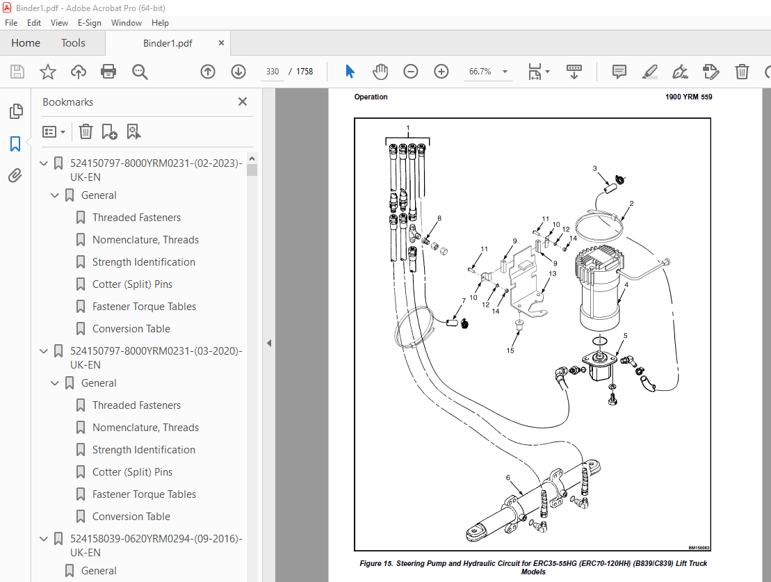
TABLE OF CONTENTS:
Yale Forklift E216 (ERP20ALF, ERP25ALF, ERP30ALF, ERP32ALF) Service Manual – PDF DOWNLOAD
524150797-8000YRM0231-(02-2023)-UK-EN 1
General 7
Threaded Fasteners 7
Nomenclature, Threads 7
Strength Identification 8
Cotter (Split) Pins 9
Fastener Torque Tables 14
Conversion Table 16
524150797-8000YRM0231-(03-2020)-UK-EN 23
General 27
Threaded Fasteners 27
Nomenclature, Threads 27
Strength Identification 28
Cotter (Split) Pins 29
Fastener Torque Tables 34
Conversion Table 36
524158039-0620YRM0294-(09-2016)-UK-EN 43
General 47
Brush and Commutator Inspection 48
Hydraulic Pump Motor and Traction Motor 48
Steering Pump Motor 51
Normal Commutator Surface 51
Commutator Problems 51
Brush Replacement 56
Stoning the Commutator 59
Motors Repair 60
Disassemble 61
Traction Motor and Hydraulic Pump Motor 61
Steering Pump Motor 62
Assemble 66
Traction Motor and Hydraulic Pump Motor 66
Steering Pump Motor 68
Brush Alignment, Traction and Hydraulic Motors 70
Tests for Damaged Field and Armature 71
Test for an Open Circuit in One Armature Winding 71
Test for Short Circuit in One Armature Winding 71
Test for Short Circuit to Armature Shaft 72
Test for Open Circuit in Field Coil 72
Test for Short Circuit in Field Coil 73
Test for Short Circuit Between Field and Motor Case 73
Brush Holder Test 73
Troubleshooting 74
524158040-2240YRM0001-(01-2023)-UK-EN 79
General 85
Battery Type 85
Lead-Acid Batteries 85
Lithium-Ion Batteries 86
Specific Gravity 86
Chemical Reaction in a Cell 86
Electrical Terms 88
Battery Selection 89
Battery Voltage 90
Battery as a Counterweight 90
Battery Ratings 90
Kilowatt-Hours 90
Battery Maintenance 91
Safety Procedures 91
Maintenance Records 91
New Battery 91
Cleaning Battery 92
Adding Water to Battery 94
Hydrometer 94
Battery Temperature 95
Charging Battery 96
Types of Battery Charges 97
Methods of Charging 98
Troubleshooting Charger 99
Knowing When Battery Is Fully Charged 99
Where to Charge Batteries 99
Equipment Needed 99
Battery Connectors 100
Battery Care 100
Troubleshooting 102
524158040-2240YRM0001-(03-2020)-UK-EN 107
General 111
Battery Type 111
Lead-Acid Batteries 111
Lithium-Ion Batteries 112
Specific Gravity 112
Chemical Reaction in a Cell 112
Electrical Terms 114
Battery Selection 114
Battery Voltage 115
Battery as a Counterweight 116
Battery Ratings 116
Kilowatt-Hours 116
Battery Maintenance 116
Safety Procedures 116
Maintenance Records 117
New Battery 117
Cleaning Battery 117
Adding Water to Battery 119
Hydrometer 120
Battery Temperature 121
Charging Battery 122
Types of Battery Charges 122
Methods of Charging 124
Troubleshooting Charger 124
Knowing When Battery Is Fully Charged 125
Where to Charge Batteries 125
Equipment Needed 125
Battery Connectors 126
Battery Care 126
Troubleshooting 128
524158752-1600YRM0316-(08-2006)-UK-EN 133
toc 133
Steering Axle 133
Safety Precautions Maintenance and Repair 134
General 137
Description 137
Steering Axle Assembly Repair 138
Remove 138
Install 138
Wheels and Hubs Repair 139
Remove and Disassemble 139
Clean 139
Assemble and Install 139
Spindles, Bearings, and Tie Rods Repair 141
Remove 141
Install 141
Steering Cylinder Repair 142
Remove and Disassemble 142
Clean and Inspect 143
Assemble and Install 143
Torque Specifications 143
Troubleshooting 144
524158753-1600YRM0720-(11-2006)-UK-EN 149
toc 149
Steering Housing and Control Unit 149
Safety Precautions Maintenance and Repair 150
General 153
Description 153
Operation 154
Steering Wheel and Column Assembly Repair 155
Assembly Components, Remove 155
Steering Control Unit, Disassemble 160
Steering Control Unit, Clean 160
Steering Control Unit, Assemble 160
Assembly Components, Install 162
System Air Removal 164
Troubleshooting 164
524158753-1600YRM0720-(11-2006)-UK-EN_2 169
toc 169
Steering Housing and Control Unit 169
Safety Precautions Maintenance and Repair 170
General 173
Description 173
Operation 174
Steering Wheel and Column Assembly Repair 175
Assembly Components, Remove 175
Steering Control Unit, Disassemble 180
Steering Control Unit, Clean 180
Steering Control Unit, Assemble 180
Assembly Components, Install 182
System Air Removal 184
Troubleshooting 184
524158890-4000YRM0521-(03-2006)-UK-EN (2) 189
toc 189
Mast 189
Safety Precautions Maintenance and Repair 190
General 193
Description and Operation 193
Carriages 193
Mast Mounts 195
Two-Stage Mast, Limited Free-Lift (LFL) 196
Description and Operation 196
Two-Stage Mast, Full Free-Lift (FFL) 198
Description and Operation 198
Three-Stage Mast, Full Free-Lift (FFL) 200
Description and Operation 200
Four-Stage Mast 202
Description and Operation 202
Cylinder Cushion During Lifting Sequence 206
Cylinder Cushion During Lowering Sequence 207
524158890-4000YRM0521-(03-2006)-UK-EN 211
toc 211
Mast 211
Safety Precautions Maintenance and Repair 212
General 215
Description and Operation 215
Carriages 215
Mast Mounts 217
Two-Stage Mast, Limited Free-Lift (LFL) 218
Description and Operation 218
Two-Stage Mast, Full Free-Lift (FFL) 220
Description and Operation 220
Three-Stage Mast, Full Free-Lift (FFL) 222
Description and Operation 222
Four-Stage Mast 224
Description and Operation 224
Cylinder Cushion During Lifting Sequence 228
Cylinder Cushion During Lowering Sequence 229
524179945-1900YRM0559-(04-2009)-UK-EN (2) 233
toc 233
Hydraulic System 233
Safety Precautions Maintenance and Repair 234
General 237
Description 237
Hydraulic System 237
Operation 245
Hydraulic System 245
Hydraulic Gear Pump 251
Steering Pump 251
Hydraulic Tank Repair 259
Tank, Remove [ERC/P16-20AAF (ERC030-040AF, AG/BG) (A814); ERC/P1 259
Tank, Remove [ERP20-30ALF (B216) and ERP20-30ALF (ERP040-060DH) 261
Tank, Remove [ERP20-32ALF (ERP040-065DH) (E216)] 262
Hydraulic Tank [ERC35-55HG (ERC70-120HH) (B839/C839)] 262
Inspect 263
Small Leaks, Repair 264
Large Leaks, Repair 264
Clean 264
Steam Method 264
Chemical Solution Method 265
Additional Methods for Tank Repair 265
Tank, Install [ERC/P16-20AAF (ERC030-040AF, AG/BG) (A814); ERC/P 265
Tank, Install [ERP20-30ALF (B216) and ERP20-30ALF (ERP040-060DH) 266
Tank, Install [ERP20-32ALF (ERP040-065DH) (E216)] 266
Filter Replacement 267
All Lift Trucks Except [ERC35-55HG (ERC70-120HH) (B839/C839); ER 267
Remove 267
Install 268
Lift Truck Models [ERC35-55HG (ERC70-120HH) (B839/C839)] 268
Remove 268
Install 268
Lift truck Models [ERC20-32AGF (ERC040-065GH) (A908) and ERC/P16 269
Remove 269
Install 269
Lift Truck Models [ERP20-32ALF (ERP040-065DH) (E216)] 271
Remove 271
Install 271
Hydraulic Pump Repair 274
Hydraulic Pump, Remove [ERC/P16-20AAF (ERC030-040AF, AG/BG) (A81 274
Hydraulic Pump, Disassemble ERC/P16-20AAF (ERC030-040AF, AG/BG) 274
Inspect 276
Clean 276
Pump Seal Replace and Pump Assemble 276
Assemble Pump on Motor 276
Hydraulic Pump and Motor, Install [ERC/P16-20AAF (ERC030-040AF, 278
Hydraulic Pump, Remove [ERP20-30ALF (B216); ERP20-30ALF (ERP040- 279
Hydraulic Pump, Disassemble [ERC35-55HG (ERC70-120HH) (B839/C839 280
Hydraulic Pump, Inspect [ERC35-55HG (ERC70-120HH) (B839/C839) an 282
Hydraulic Pump, Clean [ERC35-55HG (ERC70-120HH) (B839/C839) and 282
Hydraulic Pump, Assemble [ERC35-55HG (ERC70-120HH) (B839/C839) a 282
Hydraulic Pump and Motor, Install [ERP20-30ALF (B216); ERP20-30A 282
Main Control Valve Repair 284
Steering Pump Repair 284
Pump, Remove and Disassemble [ERC/P16-20AAF (ERC030-040AF, ERC03 284
Pump, Remove and Disassemble [ERP20-30ALF (B216); ERP20-30ALF (E 286
Pump, Assemble and Install 288
Steering Control Unit Replacement 289
Remove 289
Install 289
Steering Cylinder Repair 295
Main Control Valve Check and Adjust 295
Steering Relief Valve Check and Adjust 296
Specifications 296
Relief Valve Pressures* 296
Hydraulic Tank Capacity (dipstick full mark) 297
Hydraulic Pump Capacities – All Models Except ERC35-55HG (ERC70- 297
Hydraulic Pump Capacities – Models ERC35-55HG (ERC70-120HH) (B83 297
Troubleshooting 297
Steering 297
Steering Housing and Steering Control Unit 298
Hydraulic System 299
524179945-1900YRM0559-(04-2009)-UK-EN 305
toc 305
Hydraulic System 305
Safety Precautions Maintenance and Repair 306
General 309
Description 309
Hydraulic System 309
Operation 317
Hydraulic System 317
Hydraulic Gear Pump 323
Steering Pump 323
Hydraulic Tank Repair 331
Tank, Remove [ERC/P16-20AAF (ERC030-040AF, AG/BG) (A814); ERC/P1 331
Tank, Remove [ERP20-30ALF (B216) and ERP20-30ALF (ERP040-060DH) 333
Tank, Remove [ERP20-32ALF (ERP040-065DH) (E216)] 334
Hydraulic Tank [ERC35-55HG (ERC70-120HH) (B839/C839)] 334
Inspect 335
Small Leaks, Repair 336
Large Leaks, Repair 336
Clean 336
Steam Method 336
Chemical Solution Method 337
Additional Methods for Tank Repair 337
Tank, Install [ERC/P16-20AAF (ERC030-040AF, AG/BG) (A814); ERC/P 337
Tank, Install [ERP20-30ALF (B216) and ERP20-30ALF (ERP040-060DH) 338
Tank, Install [ERP20-32ALF (ERP040-065DH) (E216)] 338
Filter Replacement 339
All Lift Trucks Except [ERC35-55HG (ERC70-120HH) (B839/C839); ER 339
Remove 339
Install 340
Lift Truck Models [ERC35-55HG (ERC70-120HH) (B839/C839)] 340
Remove 340
Install 340
Lift truck Models [ERC20-32AGF (ERC040-065GH) (A908) and ERC/P16 341
Remove 341
Install 341
Lift Truck Models [ERP20-32ALF (ERP040-065DH) (E216)] 343
Remove 343
Install 343
Hydraulic Pump Repair 346
Hydraulic Pump, Remove [ERC/P16-20AAF (ERC030-040AF, AG/BG) (A81 346
Hydraulic Pump, Disassemble ERC/P16-20AAF (ERC030-040AF, AG/BG) 346
Inspect 348
Clean 348
Pump Seal Replace and Pump Assemble 348
Assemble Pump on Motor 348
Hydraulic Pump and Motor, Install [ERC/P16-20AAF (ERC030-040AF, 350
Hydraulic Pump, Remove [ERP20-30ALF (B216); ERP20-30ALF (ERP040- 351
Hydraulic Pump, Disassemble [ERC35-55HG (ERC70-120HH) (B839/C839 352
Hydraulic Pump, Inspect [ERC35-55HG (ERC70-120HH) (B839/C839) an 354
Hydraulic Pump, Clean [ERC35-55HG (ERC70-120HH) (B839/C839) and 354
Hydraulic Pump, Assemble [ERC35-55HG (ERC70-120HH) (B839/C839) a 354
Hydraulic Pump and Motor, Install [ERP20-30ALF (B216); ERP20-30A 354
Main Control Valve Repair 356
Steering Pump Repair 356
Pump, Remove and Disassemble [ERC/P16-20AAF (ERC030-040AF, ERC03 356
Pump, Remove and Disassemble [ERP20-30ALF (B216); ERP20-30ALF (E 358
Pump, Assemble and Install 360
Steering Control Unit Replacement 361
Remove 361
Install 361
Steering Cylinder Repair 367
Main Control Valve Check and Adjust 367
Steering Relief Valve Check and Adjust 368
Specifications 368
Relief Valve Pressures* 368
Hydraulic Tank Capacity (dipstick full mark) 369
Hydraulic Pump Capacities – All Models Except ERC35-55HG (ERC70- 369
Hydraulic Pump Capacities – Models ERC35-55HG (ERC70-120HH) (B83 369
Troubleshooting 369
Steering 369
Steering Housing and Steering Control Unit 370
Hydraulic System 371
524179946-2000YRM0562-(02-2009)-UK-EN (2) 377
toc 377
Manual hydraulic Control Valve 377
Safety Precautions Maintenance and Repair 378
General 381
Description 381
Operation 384
ERC/P16-20AAF (ERC030-040AF, AG/BG) (A814); ERC/P16-20AAF (ERC03 384
ERP20-30ALF (B216), ERP20-30ALF (ERP040-060DH) (D216) and ERP20- 384
Lift Section 386
Tilt Section 386
Tilt Backward 386
Tilt Forward 386
Relief Valve 388
Main Control Valve Repair 389
Main Control Valve Without OPS Solenoid 389
Remove 389
Disassemble 389
Clean and Inspect 393
Assemble 393
Install [ERC/P16-20AAF (ERC030-040AF, AG/BG) (A814); ERC/P16-20A 394
Install [ERP20-30ALF (B216), ERP20-30ALF (ERP040-060DH) (D216) a 394
Main Control Valve With OPS Solenoid 395
Remove 395
Disassemble 395
Clean and Inspect 397
Relief Valve Repair 399
Assemble 400
Install 401
Control Lever Linkage Repair 401
Remove [ERC/P16-20AAF (ERC030-040AF, AG/BG) (A814),ERC/P16-20AAF 401
Disassemble [ERC/P16-20AAF (ERC030-040AF, AG/BG) (A814),ERC/P16- 401
Assemble and Install [ERC/P16-20AAF (ERC030-040AF, AG/BG) (A814) 403
Control Valve Linkage Repair 403
Remove and Disassemble [ERC/P16-20AAF (ERC030-040AF, AG/BG) (A81 403
Assemble and Install [ERC/P16-20AAF (ERC030-040AF, AG/BG) (A814) 404
Control Lever Linkage Repair 404
Remove [ERP20-30ALF (B216), ERP20-30ALF (ERP040-060DH) (D216) an 404
Disassemble [ERP20-30ALF (B216), ERP20-30ALF (ERP040-060DH) (D21 406
Assemble and Install [ERP20-30ALF (B216), ERP20-30ALF (ERP040-06 406
Pressure Relief Valve Check and Adjustment 407
Primary Relief Valve 407
Secondary Relief Valve 408
Troubleshooting 409
524179946-2000YRM0562-(02-2009)-UK-EN 413
toc 413
Manual hydraulic Control Valve 413
Safety Precautions Maintenance and Repair 414
General 417
Description 417
Operation 420
ERC/P16-20AAF (ERC030-040AF, AG/BG) (A814); ERC/P16-20AAF (ERC03 420
ERP20-30ALF (B216), ERP20-30ALF (ERP040-060DH) (D216) and ERP20- 420
Lift Section 422
Tilt Section 422
Tilt Backward 422
Tilt Forward 422
Relief Valve 424
Main Control Valve Repair 425
Main Control Valve Without OPS Solenoid 425
Remove 425
Disassemble 425
Clean and Inspect 429
Assemble 429
Install [ERC/P16-20AAF (ERC030-040AF, AG/BG) (A814); ERC/P16-20A 430
Install [ERP20-30ALF (B216), ERP20-30ALF (ERP040-060DH) (D216) a 430
Main Control Valve With OPS Solenoid 431
Remove 431
Disassemble 431
Clean and Inspect 433
Relief Valve Repair 435
Assemble 436
Install 437
Control Lever Linkage Repair 437
Remove [ERC/P16-20AAF (ERC030-040AF, AG/BG) (A814),ERC/P16-20AAF 437
Disassemble [ERC/P16-20AAF (ERC030-040AF, AG/BG) (A814),ERC/P16- 437
Assemble and Install [ERC/P16-20AAF (ERC030-040AF, AG/BG) (A814) 439
Control Valve Linkage Repair 439
Remove and Disassemble [ERC/P16-20AAF (ERC030-040AF, AG/BG) (A81 439
Assemble and Install [ERC/P16-20AAF (ERC030-040AF, AG/BG) (A814) 440
Control Lever Linkage Repair 440
Remove [ERP20-30ALF (B216), ERP20-30ALF (ERP040-060DH) (D216) an 440
Disassemble [ERP20-30ALF (B216), ERP20-30ALF (ERP040-060DH) (D21 442
Assemble and Install [ERP20-30ALF (B216), ERP20-30ALF (ERP040-06 442
Pressure Relief Valve Check and Adjustment 443
Primary Relief Valve 443
Secondary Relief Valve 444
Troubleshooting 445
524183080-0620YRM1053-(03-2010)-UK-EN (2) 449
toc 449
AC Motor Repair 449
Safety Precautions Maintenance and Repair 450
General 453
AC Motor Repair 454
Disassemble 454
Assemble 456
Drive End Bearing, Replace 457
Disassemble, ERP20-32ALF (ERP040-065DH) (E216) Traction Motor 457
Assemble, ERP20-32ALF (ERP040-065DH) (E216) Traction Motor 459
Troubleshooting 460
524183080-0620YRM1053-(03-2010)-UK-EN 463
toc 463
AC Motor Repair 463
Safety Precautions Maintenance and Repair 464
General 467
AC Motor Repair 468
Disassemble 468
Assemble 470
Drive End Bearing, Replace 471
Disassemble, ERP20-32ALF (ERP040-065DH) (E216) Traction Motor 471
Assemble, ERP20-32ALF (ERP040-065DH) (E216) Traction Motor 473
Troubleshooting 474
524183081-1600YRM1054-(11-2006)-UK-EN (2) 477
toc 477
Steering System for AC Electric Lift Trucks 477
Safety Precautions Maintenance and Repair 478
General 481
Description 482
Steering Wheel and Column Assembly Repair 483
General 483
Assembly Components, Remove 485
Assembly Components, Install 486
Power Steering Motor and Pump 487
Description 487
Remove 487
Disassemble 490
Install 490
Power Steering Pump, Repair 490
Seal, Replace 491
Steering System Air Removal 492
Steering Pressure Check 492
Steering Motor Circuits Check 493
Troubleshooting 494
524183081-1600YRM1054-(11-2006)-UK-EN 499
toc 499
Steering System for AC Electric Lift Trucks 499
Safety Precautions Maintenance and Repair 500
General 503
Description 504
Steering Wheel and Column Assembly Repair 505
General 505
Assembly Components, Remove 507
Assembly Components, Install 508
Power Steering Motor and Pump 509
Description 509
Remove 509
Disassemble 512
Install 512
Power Steering Pump, Repair 512
Seal, Replace 513
Steering System Air Removal 514
Steering Pressure Check 514
Steering Motor Circuits Check 515
Troubleshooting 516
524183082-2200YRM1055-(10-2009)-UK-EN (2) 521
toc 521
Electrical System (Trucks With AC Controllers) 521
Safety Precautions Maintenance and Repair 522
General 525
Description 526
Features of the Display Panels 526
Other Control Components 527
Display Panel and Key Switch Replacement 528
Display Panel, Replace 528
Key Switch, Replace 530
Controller Replacement 530
Traction and Pump Motor Controller Replacement 530
Master Controller, Replace 536
Master Controller, Remove ERP20-30ALF (ERP040-060DH) (D216), ERP 536
Master Controller, Install ERP20-30ALF (ERP040-060DH) (D216), ER 536
Master Controller, Remove ERC/P16-20AAF (ERC030-040AH) (B814/C81 538
Master Controller, Install ERC/P16-20AAF (ERC030-040AH) (B814/C8 538
Master Controller, Remove ERC35-55HG (ERC070-120HH) (B839/C839) 540
Master Controller, Install ERC35-55HG (ERC070-120HH) (B839/C839) 540
Control Components Replacement 541
General 541
Start Switch, Replace 541
Brake Light Switch, Replace 542
Seat Switch, Replace 542
Parking Brake Switch, Replace 543
Foot Directional Control Pedal Direction Switches, Replace 545
Steering Column Direction Control Switches, Replace 548
Remove 548
Install 548
Brake Fluid Switch, Replace 550
Brush Wear and Over Temperature Sensors (DC Pump Motor Only) 550
Rocker Switches for Lights, Replace 550
Accelerator Position Sensor, Replace 551
On-Demand Steering Sensor, Replace 552
Lights, Converter, Relay, and Reverse Alarm 552
Brake, Tail, and Reverse Light Assembly, Replace 553
Incandescent Assembly 553
LED Assembly – Remove 555
LED Assembly – Install 555
Strobe Light Assembly, Replace 558
Wire Harness Repair 559
Del-City Crimp-Solder-Shrink Splice 559
Front, Rear Driving Light or Spot Light Assemblies, Replace 560
Converter, Replace 560
Remove, Lift Truck Models ERP20-30ALF (ERP040-060DH) (D216), ERP 560
Install, Lift Truck Models ERP20-30ALF (ERP040-060DH) (D216), ER 562
Remove, Lift Truck Models ERC20-32AGF (ERC040-065GH) (A908) and 562
Install, Lift Truck Models ERC20-32AGF (ERC040-065GH) (A908) and 562
Remove, Lift Truck Models ERC35-55HG (ERC70-120HH) (B839/C839) 564
Install, Lift Truck Models ERC35-55HG (ERC70-120HH) (B839/C839) 564
Reverse Relay, Replace 565
Lift Truck Models ERC20-32AGF (ERC040-065GH) (A908), ERC/P16-20A 565
Lift Truck Models ERC35-55HG (ERC70-120HH) (B839/C839) 565
Backup Alarm, Replace 567
Horn and Horn Button, Replace 567
Horn Replacement for Lift Trucks ERP20-30ALF (ERP040-060DH) (D21 567
Horn Replacement for Lift Trucks ERC35-55HG (ERC70-120HH) (B839/ 569
Horn Switch and Cover, Replace 570
Hydraulic Pump Switches 571
Fan Power Supply, Replace 571
Remove, Lift Truck Models ERC35-55HG (ERC70-120HH) (B839/C839) 571
Install, Lift Truck Models ERC35-55HG (ERC70-120HH) (B839/C839) 571
Remove, Lift Truck Models ERP20-30ALF (ERP040-060DH) (D216) and 572
Install, Lift Truck Models ERP20-30ALF (ERP040-060DH) (D216) and 573
Remove, Lift Truck Models ERC20-32AGF (ERC040-065GH) (A908) 573
Install, Lift Truck Models ERC20-32AGF (ERC040-065GH) (A908) 573
Control and Power Fuse Check 574
Fuse Locations 574
Brake Light Switch Adjustment 580
Seat Switch Check 581
Seat Brake Adjustment 581
Parking Brake Switch Adjustment 582
Direction Switches Check 582
Foot Directional Control Pedal 582
Steering Column 583
Foot Directional Control Pedal or Accelerator Pedal Adjustment 583
Accelerator Position Sensor Adjustment and Start Switch Adjustme 584
Acceleration Position Sensor, Adjust 584
Start Switch, Adjust 586
tables 521
Table 1 Wire Splice Size 559
524183082-2200YRM1055-(10-2009)-UK-EN 589
toc 589
Electrical System (Trucks With AC Controllers) 589
Safety Precautions Maintenance and Repair 590
General 593
Description 594
Features of the Display Panels 594
Other Control Components 595
Display Panel and Key Switch Replacement 596
Display Panel, Replace 596
Key Switch, Replace 598
Controller Replacement 598
Traction and Pump Motor Controller Replacement 598
Master Controller, Replace 604
Master Controller, Remove ERP20-30ALF (ERP040-060DH) (D216), ERP 604
Master Controller, Install ERP20-30ALF (ERP040-060DH) (D216), ER 604
Master Controller, Remove ERC/P16-20AAF (ERC030-040AH) (B814/C81 606
Master Controller, Install ERC/P16-20AAF (ERC030-040AH) (B814/C8 606
Master Controller, Remove ERC35-55HG (ERC070-120HH) (B839/C839) 608
Master Controller, Install ERC35-55HG (ERC070-120HH) (B839/C839) 608
Control Components Replacement 609
General 609
Start Switch, Replace 609
Brake Light Switch, Replace 610
Seat Switch, Replace 610
Parking Brake Switch, Replace 611
Foot Directional Control Pedal Direction Switches, Replace 613
Steering Column Direction Control Switches, Replace 616
Remove 616
Install 616
Brake Fluid Switch, Replace 618
Brush Wear and Over Temperature Sensors (DC Pump Motor Only) 618
Rocker Switches for Lights, Replace 618
Accelerator Position Sensor, Replace 619
On-Demand Steering Sensor, Replace 620
Lights, Converter, Relay, and Reverse Alarm 620
Brake, Tail, and Reverse Light Assembly, Replace 621
Incandescent Assembly 621
LED Assembly – Remove 623
LED Assembly – Install 623
Strobe Light Assembly, Replace 626
Wire Harness Repair 627
Del-City Crimp-Solder-Shrink Splice 627
Front, Rear Driving Light or Spot Light Assemblies, Replace 628
Converter, Replace 628
Remove, Lift Truck Models ERP20-30ALF (ERP040-060DH) (D216), ERP 628
Install, Lift Truck Models ERP20-30ALF (ERP040-060DH) (D216), ER 630
Remove, Lift Truck Models ERC20-32AGF (ERC040-065GH) (A908) and 630
Install, Lift Truck Models ERC20-32AGF (ERC040-065GH) (A908) and 630
Remove, Lift Truck Models ERC35-55HG (ERC70-120HH) (B839/C839) 632
Install, Lift Truck Models ERC35-55HG (ERC70-120HH) (B839/C839) 632
Reverse Relay, Replace 633
Lift Truck Models ERC20-32AGF (ERC040-065GH) (A908), ERC/P16-20A 633
Lift Truck Models ERC35-55HG (ERC70-120HH) (B839/C839) 633
Backup Alarm, Replace 635
Horn and Horn Button, Replace 635
Horn Replacement for Lift Trucks ERP20-30ALF (ERP040-060DH) (D21 635
Horn Replacement for Lift Trucks ERC35-55HG (ERC70-120HH) (B839/ 637
Horn Switch and Cover, Replace 638
Hydraulic Pump Switches 639
Fan Power Supply, Replace 639
Remove, Lift Truck Models ERC35-55HG (ERC70-120HH) (B839/C839) 639
Install, Lift Truck Models ERC35-55HG (ERC70-120HH) (B839/C839) 639
Remove, Lift Truck Models ERP20-30ALF (ERP040-060DH) (D216) and 640
Install, Lift Truck Models ERP20-30ALF (ERP040-060DH) (D216) and 641
Remove, Lift Truck Models ERC20-32AGF (ERC040-065GH) (A908) 641
Install, Lift Truck Models ERC20-32AGF (ERC040-065GH) (A908) 641
Control and Power Fuse Check 642
Fuse Locations 642
Brake Light Switch Adjustment 648
Seat Switch Check 649
Seat Brake Adjustment 649
Parking Brake Switch Adjustment 650
Direction Switches Check 650
Foot Directional Control Pedal 650
Steering Column 651
Foot Directional Control Pedal or Accelerator Pedal Adjustment 651
Accelerator Position Sensor Adjustment and Start Switch Adjustme 652
Acceleration Position Sensor, Adjust 652
Start Switch, Adjust 654
tables 589
Table 1 Wire Splice Size 627
524183083-2200YRM1056-(03-2009)-UK-EN (2) 657
toc 657
AC Motor Controllers/Display Panel 657
Safety Precautions Maintenance and Repair 658
Description 661
General 661
AC Motors 661
Motor Controllers 661
Master Controller 661
Dash Display 661
Controller Area Network Bus (CANbus) 661
Master Controller Checks and Adjustments 662
Function Settings 663
General 663
Function Numbers 663
Function Descriptions 666
General 666
Function Number 1 BATTERY VOLTAGE 666
Function Number 2 EXTENDED SHIFT 666
Function Number 3 ACCELERATION 1 666
Function Number 4 ACCELERATION 2 666
Function Number 5 TOP SPEED LIMIT 666
Function Number 6 REGEN BRAKING 666
Function Number 7 AUTO DECELERATION 667
Function Number 8 BDI ADJUSTMENT 667
Function Number 9 LIFT INTERRUPT 667
Function Number 10 POWER STEERING TIME DELAY 667
Function Number 11 SERVICE REMINDER 667
Function Number 12 CUSTOM 667
Function Number 13 PUMP SPEED 1 667
Function Number 14 PUMP SPEED 2 668
Function Number 15 PUMP SPEED 3 668
Function Number 16 PUMP ACCELERATION 668
Troubleshooting 668
General 668
Controller Status Light Emitting Diodes (LEDs) 669
Master Controller 669
AC Motor Controllers 669
Status Codes 675
AC Motor Controllers Status Code Charts 677
Troubleshooting When Dash and/or Lift Truck is not Operational 698
Typical Symptoms 698
Truck Runs but Dash Display is not Operational, or Only Displays 698
Truck Does Not Run and Dash is Not Operational or Only Displays 699
Hydraulics Operate Normally, Traction Does Not Operate Correctly 700
Traction Operates Normally, Hydraulics do Not Operate Correctly, 700
AC Transistor Motor Controller Replacement 700
General 700
General Maintenance Instructions 706
Special Precautions 706
Fuses 707
Fan Test 707
Contactors 707
Repair 707
Thermal Sensors 711
Motor Controller, Replace 711
Display Panel 712
General 712
Premium Display Panel 712
Standard Display Panel 712
Display Functions and Features 713
Key-On Initialization 713
Standard Display 714
Premium Display 714
Lift Truck Inspection Function 715
Access to Service Functions 715
Service Functions 715
Service Functions 716
Performance Modes 718
Battery Discharge Indicator (BDI) 718
Hourmeter 719
Dash Display Service Menu Navigation 725
General 725
Moving Through Menu Selections 725
Editing and Adding Information 725
tables 657
Table 1 Factory Parameters for ERP20-30ALF (ERP040-060DH) (D216 663
Table 2 Factory Setting for ERC020-032AGF (ERC40-65GH) (A908) 664
Table 3 Factory Setting for ERC/P16-20AAF (ERC030-040AH) (B814/ 664
Table 4 Factory Parameters for ERC35-55HG (ERC70-120HH) (B839/C 665
Table 5 List of Status Codes 675
Table 6 42-Pin Connections/Descriptions for Master Controller 708
Table 7 Pin Connections/Descriptions for 72/80 (Gen IV) Volt Mo 710
Table 8 Pin Connections/Descriptions for 36/48 and 72v/80v (Gen 710
524183083-2200YRM1056-(03-2009)-UK-EN 729
toc 729
AC Motor Controllers/Display Panel 729
Safety Precautions Maintenance and Repair 730
Description 733
General 733
AC Motors 733
Motor Controllers 733
Master Controller 733
Dash Display 733
Controller Area Network Bus (CANbus) 733
Master Controller Checks and Adjustments 734
Function Settings 735
General 735
Function Numbers 735
Function Descriptions 738
General 738
Function Number 1 BATTERY VOLTAGE 738
Function Number 2 EXTENDED SHIFT 738
Function Number 3 ACCELERATION 1 738
Function Number 4 ACCELERATION 2 738
Function Number 5 TOP SPEED LIMIT 738
Function Number 6 REGEN BRAKING 738
Function Number 7 AUTO DECELERATION 739
Function Number 8 BDI ADJUSTMENT 739
Function Number 9 LIFT INTERRUPT 739
Function Number 10 POWER STEERING TIME DELAY 739
Function Number 11 SERVICE REMINDER 739
Function Number 12 CUSTOM 739
Function Number 13 PUMP SPEED 1 739
Function Number 14 PUMP SPEED 2 740
Function Number 15 PUMP SPEED 3 740
Function Number 16 PUMP ACCELERATION 740
Troubleshooting 740
General 740
Controller Status Light Emitting Diodes (LEDs) 741
Master Controller 741
AC Motor Controllers 741
Status Codes 747
AC Motor Controllers Status Code Charts 749
Troubleshooting When Dash and/or Lift Truck is not Operational 770
Typical Symptoms 770
Truck Runs but Dash Display is not Operational, or Only Displays 770
Truck Does Not Run and Dash is Not Operational or Only Displays 771
Hydraulics Operate Normally, Traction Does Not Operate Correctly 772
Traction Operates Normally, Hydraulics do Not Operate Correctly, 772
AC Transistor Motor Controller Replacement 772
General 772
General Maintenance Instructions 778
Special Precautions 778
Fuses 779
Fan Test 779
Contactors 779
Repair 779
Thermal Sensors 783
Motor Controller, Replace 783
Display Panel 784
General 784
Premium Display Panel 784
Standard Display Panel 784
Display Functions and Features 785
Key-On Initialization 785
Standard Display 786
Premium Display 786
Lift Truck Inspection Function 787
Access to Service Functions 787
Service Functions 787
Service Functions 788
Performance Modes 790
Battery Discharge Indicator (BDI) 790
Hourmeter 791
Dash Display Service Menu Navigation 797
General 797
Moving Through Menu Selections 797
Editing and Adding Information 797
tables 729
Table 1 Factory Parameters for ERP20-30ALF (ERP040-060DH) (D216 735
Table 2 Factory Setting for ERC020-032AGF (ERC40-65GH) (A908) 736
Table 3 Factory Setting for ERC/P16-20AAF (ERC030-040AH) (B814/ 736
Table 4 Factory Parameters for ERC35-55HG (ERC70-120HH) (B839/C 737
Table 5 List of Status Codes 747
Table 6 42-Pin Connections/Descriptions for Master Controller 780
Table 7 Pin Connections/Descriptions for 72/80 (Gen IV) Volt Mo 782
Table 8 Pin Connections/Descriptions for 36/48 and 72v/80v (Gen 782
524183085-2200YRM1058-(04-2011)-UK-EN (2) 801
toc 801
Troubleshooting and Adjustments Using the AC Controls Program (E 801
Safety Precautions Maintenance and Repair 802
General 805
Computer Requirements 805
Software, Install 805
Language Selection 805
Demo Mode 806
Connect PC to Lift Truck 810
Starting AC Controls Program 812
Lift Truck Control Setup 817
Change Lift Truck Serial Number or Hourmeter 817
Setting Factory Default Values or Changing Lift Truck Parameters 818
Create New Custom Lift Truck Configuration 824
Lift Truck Configuration Properties 827
Import New Lift Truck Configuration From Disk 830
Delete Custom Lift Truck Configuration or Password File 832
Dash Display 835
Custom Display Languages 835
Download Display Language 837
Clear Operator Log 837
Password Functions 840
Enable/Disable Password and Lift Truck Inspection Functions 840
Truck Inspection Checklist 840
Password 840
Password Properties 840
Create New Password File 845
Download Passwords 846
Upload Passwords 848
Reports Menu 850
Devices Report 850
Custom Report 850
Password Report 850
Operator Report 857
Current Settings Report 860
Status Code Report 864
Status Codes Log 867
Troubleshooting 869
Diagnostics 869
Help Menu 872
General 872
Contents 872
Technical Support 872
About Electric Truck AC Controls Program 872
524183085-2200YRM1058-(04-2011)-UK-EN 879
toc 879
Troubleshooting and Adjustments Using the AC Controls Program (E 879
Safety Precautions Maintenance and Repair 880
General 883
Computer Requirements 883
Software, Install 883
Language Selection 883
Demo Mode 884
Connect PC to Lift Truck 888
Starting AC Controls Program 890
Lift Truck Control Setup 895
Change Lift Truck Serial Number or Hourmeter 895
Setting Factory Default Values or Changing Lift Truck Parameters 896
Create New Custom Lift Truck Configuration 902
Lift Truck Configuration Properties 905
Import New Lift Truck Configuration From Disk 908
Delete Custom Lift Truck Configuration or Password File 910
Dash Display 913
Custom Display Languages 913
Download Display Language 915
Clear Operator Log 915
Password Functions 918
Enable/Disable Password and Lift Truck Inspection Functions 918
Truck Inspection Checklist 918
Password 918
Password Properties 918
Create New Password File 923
Download Passwords 924
Upload Passwords 926
Reports Menu 928
Devices Report 928
Custom Report 928
Password Report 928
Operator Report 935
Current Settings Report 938
Status Code Report 942
Status Codes Log 945
Troubleshooting 947
Diagnostics 947
Help Menu 950
General 950
Contents 950
Technical Support 950
About Electric Truck AC Controls Program 950
524223768-2100YRM1139-(02-2014)-UK-EN 957
524223776-4000YRM1148-(09-2015)-UK-EN 1005
General 1009
Safety Procedures When Working Near Mast 1010
Fork Replacement 1012
Remove, Lift Trucks Not Equipped With Fork Positioner Or Equipped With Fork Positioner Before August, 2012 1012
Remove, Lift Trucks Manufactured After August, 2012 And Equipped With Fork Positioner 1014
Install, Lift Trucks Not Equipped With Fork Positioner Or Equipped With Fork Positioner Before August, 2012 1015
Install, Lift Trucks Manufactured After August, 2012 And Equipped With Fork Positioner 1015
Checks, Lift Trucks Not Equipped With Fork Positioner Or Equipped With Fork Positioner Before August, 2012 1016
Checks, Lift Trucks Manufactured After August, 2012 And Equipped With Fork Positioner 1017
Carriages Repair 1018
Standard Carriage 1018
Remove 1018
Repair 1019
Install 1019
Standard Carriage, Remove 1020
Hang-On Sideshift Carriage, Remove 1021
Standard Carriage and Hang-On Sideshift Carriage, Repair 1022
Standard Carriage, Install 1023
Hang-On Sideshift Carriage, Install 1023
Integral Sideshift Carriage 1024
Remove 1024
Clean and Inspect 1027
Repair 1028
Install 1028
Fork Positioner 1029
Remove 1029
Clean and Inspect 1034
Disassemble and Assemble 1034
Install 1034
Fork Positioner Hydraulic Hose Adjustment 1035
Disconnecting Attachment Hydraulic Quick Disconnect Hoses 1037
Connecting Attachment Hydraulic Quick Disconnect Hoses 1037
Mast Repair 1038
Mast, Remove 1038
Two-Stage LFL and Two-Stage FFL Masts 1041
Disassemble 1041
Clean and Inspect 1051
Three-Stage FFL Mast 1052
Disassemble 1052
Clean and Inspect 1060
Two-Stage LFL and Two-Stage FFL Mast 1062
Assemble 1062
Three-Stage FFL Mast 1065
Assemble 1065
Four-Stage FFL Mast – Manufactured Before July, 2009 1067
Disassemble 1067
Clean and Inspect 1072
Assemble 1074
Four-Stage FFL Mast – Manufactured After July, 2009 1075
Disassemble 1075
Clean and Inspect 1082
Assemble 1085
Mast, Install 1086
Header Hose Arrangement 1089
Two-Stage LFL 1089
Two-Stage FFL 1097
Three-Stage FFL 1112
Standard 1112
Optional Equipment Lift Truck GLP/GDP20-35VX (GP/GLP/GDP040-070VX) (B875) 1129
Four-Stage FFL Mast – Manufactured Before July, 2009 1137
Four-Stage FFL Mast – Manufactured After July, 2009 1146
Adjustment 1153
Lift Chains Adjustment 1153
Carriage Adjustments 1156
Mast Adjustments 1156
Load Roller Adjustment 1156
Mast Side Kicking Adjustment 1159
524256685-0100YRM1222-(05-2006)-UK-EN (2) 1163
toc 1163
Frame 1163
Safety Precautions Maintenance and Repair 1164
General 1167
Description 1167
Main Frame 1167
Other Frame Weldments 1167
Overhead Guard 1167
Battery Restraint, Hood, and Seat Assembly 1171
Hood With Manual Hydraulic Levers 1172
Hood With E-Hydraulics 1173
Operator Restraint System and Seat Assembly 1174
Operator Restraint System 1174
Emergency Locking Retractor (ELR) 1174
Hood and Seat Latches 1175
Overhead Guard Replacement 1175
Remove 1175
Install 1175
Hood, Seat Assembly, and Operator Restraint Replacement 1177
Hood and Seat Assembly 1177
Remove 1177
Install 1179
Counterweight Replacement 1183
Remove 1183
Install 1183
Hydraulic Tank Replacement 1184
Remove 1184
Inspect 1184
Clean 1185
Steam Method 1185
Chemical Solution Method 1185
Additional Preparations for Tank Repair 1186
Small Leaks, Repair 1186
Large Leaks, Repair 1186
Preparations for Usage After Repair 1186
Install 1186
Painting Instructions 1187
Safety Label Replacement 1189
Battery Specifications 1191
ERP20-32ALF (ERP040-065DH) (E216) Model Trucks 1191
tables 1163
Table 1 Counterweights 1183
524256685-0100YRM1222-(05-2006)-UK-EN 1195
toc 1195
Frame 1195
Safety Precautions Maintenance and Repair 1196
General 1199
Description 1199
Main Frame 1199
Other Frame Weldments 1199
Overhead Guard 1199
Battery Restraint, Hood, and Seat Assembly 1203
Hood With Manual Hydraulic Levers 1204
Hood With E-Hydraulics 1205
Operator Restraint System and Seat Assembly 1206
Operator Restraint System 1206
Emergency Locking Retractor (ELR) 1206
Hood and Seat Latches 1207
Overhead Guard Replacement 1207
Remove 1207
Install 1207
Hood, Seat Assembly, and Operator Restraint Replacement 1209
Hood and Seat Assembly 1209
Remove 1209
Install 1211
Counterweight Replacement 1215
Remove 1215
Install 1215
Hydraulic Tank Replacement 1216
Remove 1216
Inspect 1216
Clean 1217
Steam Method 1217
Chemical Solution Method 1217
Additional Preparations for Tank Repair 1218
Small Leaks, Repair 1218
Large Leaks, Repair 1218
Preparations for Usage After Repair 1218
Install 1218
Painting Instructions 1219
Safety Label Replacement 1221
Battery Specifications 1223
ERP20-32ALF (ERP040-065DH) (E216) Model Trucks 1223
tables 1195
Table 1 Counterweights 1215
524256686-1400YRM1223-(03-2009)-UK-EN (2) 1227
toc 1227
Drive Unit Assembly 1227
Safety Precautions Maintenance and Repair 1228
General 1231
Description 1231
Wet Disc Brake Repair 1235
Wet Disc Brakes 1235
Remove 1235
Inspect 1239
Install 1239
Gearbox Replacement 1244
Remove 1244
Gearbox Removal 1244
Intermediate Flange Removal 1245
Disassemble 1247
Intermediate Flange 1247
Assemble 1255
Intermediate Flange 1255
Install 1268
Intermediate Flange Installation 1268
Gearbox Installation 1270
Drive Unit Removal 1272
Main Housing Repair 1276
Main Housing, Right-Hand Side 1276
Remove 1276
Disassemble 1277
Clean and Inspect 1278
Assemble 1279
Install 1279
Main Housing, Left-Hand Side 1280
Remove 1280
Disassemble 1281
Clean and Inspect 1282
Assemble 1282
Install 1282
Differential Assembly Replacement 1283
Remove 1283
Install 1283
Traction Motor Repair 1284
Remove 1284
Disassemble 1284
Assemble 1287
Install 1287
Drive Unit Installation 1288
Torque Specifications 1289
Troubleshooting 1290
524256686-1400YRM1223-(03-2009)-UK-EN 1293
toc 1293
Drive Unit Assembly 1293
Safety Precautions Maintenance and Repair 1294
General 1297
Description 1297
Wet Disc Brake Repair 1301
Wet Disc Brakes 1301
Remove 1301
Inspect 1305
Install 1305
Gearbox Replacement 1310
Remove 1310
Gearbox Removal 1310
Intermediate Flange Removal 1311
Disassemble 1313
Intermediate Flange 1313
Assemble 1321
Intermediate Flange 1321
Install 1334
Intermediate Flange Installation 1334
Gearbox Installation 1336
Drive Unit Removal 1338
Main Housing Repair 1342
Main Housing, Right-Hand Side 1342
Remove 1342
Disassemble 1343
Clean and Inspect 1344
Assemble 1345
Install 1345
Main Housing, Left-Hand Side 1346
Remove 1346
Disassemble 1347
Clean and Inspect 1348
Assemble 1348
Install 1348
Differential Assembly Replacement 1349
Remove 1349
Install 1349
Traction Motor Repair 1350
Remove 1350
Disassemble 1350
Assemble 1353
Install 1353
Drive Unit Installation 1354
Torque Specifications 1355
Troubleshooting 1356
524256687-2000YRM1224-(04-2008)-UK-EN (2) 1359
toc 1359
Electro-hydraulic Control Valve 1359
Safety Precautions Maintenance and Repair 1360
General 1363
Description 1363
Electro-Hydraulic Control System 1363
Electro-Hydraulic Control Valve 1366
Electro-Hydraulic Valve Driver Module 1382
Mini-Lever Module (MLM) 1382
Joystick 1383
Electro-Hydraulic Control Valve Repair 1384
Remove 1384
Disassemble 1393
Solenoid Coil Replacement 1395
Cartridge Replacement 1397
Electro-Hydraulic Pressure Reducing Valve (EHPR) Replacement 1398
Lift Circuit Check Valve Replacement 1399
Compensator Cartridge Replacement 1399
Primary and Secondary Relief Valves Replacement 1399
Tilt Counterbalance Valve Replacement 1400
Flow Regulator Valve Replacement 1400
Assemble 1400
Install 1400
E-Hydraulics Calibration 1409
Mini-Lever Module 1411
Mini-Lever Module (MLM) 1411
Remove 1411
Install 1411
Mini-Lever Replacement 1411
Remove 1411
Clean and Inspect 1412
Install 1412
Push Button Switch Replacement 1413
Remove 1413
Install 1414
Test 1415
Mini-levers 1415
Full Stroke Test 1415
Function Returns to Neutral Test 1415
Push Button Switch 1416
Joystick 1416
Remove and Disassemble 1416
Inspect 1416
Assemble and Install 1416
Troubleshooting 1417
tables 1359
Table 1 Primary and Secondary Relief Valve Values 1369
Table 2 Solenoid Resistance Values 1395
Table 3 Cartridge and Solenoid Coil Nut Torque for Lift truck M 1398
Table 4 Cartridge and Solenoid Coil Nut Torque for Lift truck M 1398
524256687-2000YRM1224-(04-2008)-UK-EN 1429
toc 1429
Electro-hydraulic Control Valve 1429
Safety Precautions Maintenance and Repair 1430
General 1433
Description 1433
Electro-Hydraulic Control System 1433
Electro-Hydraulic Control Valve 1436
Electro-Hydraulic Valve Driver Module 1452
Mini-Lever Module (MLM) 1452
Joystick 1453
Electro-Hydraulic Control Valve Repair 1454
Remove 1454
Disassemble 1463
Solenoid Coil Replacement 1465
Cartridge Replacement 1467
Electro-Hydraulic Pressure Reducing Valve (EHPR) Replacement 1468
Lift Circuit Check Valve Replacement 1469
Compensator Cartridge Replacement 1469
Primary and Secondary Relief Valves Replacement 1469
Tilt Counterbalance Valve Replacement 1470
Flow Regulator Valve Replacement 1470
Assemble 1470
Install 1470
E-Hydraulics Calibration 1479
Mini-Lever Module 1481
Mini-Lever Module (MLM) 1481
Remove 1481
Install 1481
Mini-Lever Replacement 1481
Remove 1481
Clean and Inspect 1482
Install 1482
Push Button Switch Replacement 1483
Remove 1483
Install 1484
Test 1485
Mini-levers 1485
Full Stroke Test 1485
Function Returns to Neutral Test 1485
Push Button Switch 1486
Joystick 1486
Remove and Disassemble 1486
Inspect 1486
Assemble and Install 1486
Troubleshooting 1487
tables 1429
Table 1 Primary and Secondary Relief Valve Values 1439
Table 2 Solenoid Resistance Values 1465
Table 3 Cartridge and Solenoid Coil Nut Torque for Lift truck M 1468
Table 4 Cartridge and Solenoid Coil Nut Torque for Lift truck M 1468
524256688-8000YRM1225-(05-2006)-UK-EN (2) 1499
toc 1499
Electrical Diagrams 1499
Safety Precautions Maintenance and Repair 1500
524256688-8000YRM1225-(05-2006)-UK-EN 1533
toc 1533
Electrical Diagrams 1533
Safety Precautions Maintenance and Repair 1534
524256689-8000YRM1226-(08-2008)-UK-EN 1567
toc 1567
Periodic Maintenance 1567
Safety Precautions Maintenance and Repair 1568
General 1573
Serial Number Data 1573
How to Move A Disabled Lift Truck 1573
How to Tow a Lift Truck 1573
How to Put Lift Truck on Blocks 1574
How to Raise Drive Tires 1574
How to Raise Steering Tires 1575
Maintenance Schedule 1576
Maintenance Procedures Every 8 Hours or Daily 1579
How to Make Checks With Key Switch OFF 1579
Tires and Wheels 1580
Forks 1580
Inspect 1580
Mast, Carriage, Header Hoses, and Lift Chains, Inspect 1581
Safety Labels 1582
Steering Column Latch 1582
Operator Restraint System 1583
Emergency Locking Retractor (ELR) 1583
Seat Rails 1584
Battery Restraint System 1584
Battery 1584
Hydraulic System 1585
How to Make Checks With Key Switch ON 1585
Horn, Lights, and Alarm 1585
Steering System 1586
Service Brakes 1586
Parking Brake 1586
Hydraulic Control Levers 1586
Direction and Speed Control Pedals 1586
Lift System Operation 1587
Oil Leaks 1587
Seat Switch 1587
First Service After First 100 Hours of Operation 1588
Change Filter for Hydraulic Oil 1588
Remove 1588
Install 1588
Maintenance Procedures Every 500 Hours or 3 Months 1591
Wheel Nut Torque 1591
Header Hose Checks 1591
Mast 1591
Forks 1593
Remove 1593
Inspect 1594
Install 1594
Adjust 1594
Parking Brake Adjustment 1595
Maintenance Procedures Every 1000 Hours or 6 Months 1595
Lift Chains 1595
Wear Check 1595
Lift Chain Lubrication 1595
Forks 1596
Check Upper and Lower Bearings, Integral Sideshift Carriage 1596
Steering Tie Rods 1597
Steering Axle Spindles 1597
King Pins 1597
Gearbox and Brake Chamber 1598
Brake Oil 1599
Electrical Inspection 1599
AC and DC Hydraulic Pump Motor 1599
Contactors 1602
Other Lubrication 1602
Maintenance Procedures Every 2000 Hours or Yearly 1602
Change Filter for Hydraulic Oil 1602
Remove 1602
Install 1602
Change Hydraulic Oil 1604
Hydraulic Tank Breather 1604
Remove 1604
Install 1604
Gearbox and Brake Oil Replacement 1605
Remove 1605
Install 1605
Brake Oil Replacement 1606
Wheel Bearings 1606
Steer Wheels, Lubrication 1606
Lift Chains 1606
Forks 1606
Replace Upper and Lower Bearings, Integral Sideshift Carriage 1607
Other Lubrication 1607
Battery Maintenance 1607
How to Charge Battery 1607
How to Change Battery 1608
General 1608
Lift and System Leak Check 1610
Lift Cylinders Leak Check 1610
Tilt Cylinders Leak Check 1611
Safety Procedures When Working Near Mast 1611
WHEN WORKING NEAR THE MAST ALWAYS: 1611
Lift Chain Adjustment 1613
Welding Repairs 1614
Overhead Guard Changes 1615
Wheels and Tire Maintenance 1615
Pneumatic Tires and Wheels 1615
Remove Wheels From Lift Truck 1615
Remove Wheel From Pneumatic Tire 1616
Install Three- or Four-Piece Wheel in Pneumatic Tire 1617
Add Air to Tires 1618
Wheels, Install 1618
Solid Rubber Tires on Pneumatic Wheels 1619
Remove Wheels From Lift Truck 1619
Remove Solid Rubber Tire From Pneumatic Wheel 1619
Install Solid Rubber Tire on Pneumatic Wheel 1621
Wheels, Install 1622
Snap-On Tire, Change 1622
Remove Snap-On Solid Tire From Wheel 1623
Install Snap-On Solid Tire on Wheel 1624
Adhesives and Sealants 1625
tables 1567
Table 1 Maintenance Schedule 1576
524256690-8000YRM1227-(05-2006)-UK-EN (2) 1629
toc 1629
Capacities and Specifications 1629
Safety Precautions Maintenance and Repair 1630
Counterweight 1633
Hydraulic System 1633
Steering System 1634
Wheels and Tires 1634
Battery Specifications 1635
Capacities 1635
Movement Rates (Maximum) for Tilt Cylinders 1636
Mast Speeds 1636
Mast Speeds – ERP20-32ALF (72 or 80 Volt) Europe 1636
Mast Speeds – ERP040-065DH (72 or 80 Volt) Americas 1637
Torque Specifications 1639
Frame 1639
Drive Axle, Speed Reducer, and Differential 1639
Masts 1639
E-Hydraulic Control Valve 1639
Adhesives and Sealants 1640
tables 1629
Table 1 Manual Control Valve 1633
Table 2 E-Hydraulic Control Valve 1633
524256690-8000YRM1227-(05-2006)-UK-EN 1643
toc 1643
Capacities and Specifications 1643
Safety Precautions Maintenance and Repair 1644
Counterweight 1647
Hydraulic System 1647
Steering System 1648
Wheels and Tires 1648
Battery Specifications 1649
Capacities 1649
Movement Rates (Maximum) for Tilt Cylinders 1650
Mast Speeds 1650
Mast Speeds – ERP20-32ALF (72 or 80 Volt) Europe 1650
Mast Speeds – ERP040-065DH (72 or 80 Volt) Americas 1651
Torque Specifications 1653
Frame 1653
Drive Axle, Speed Reducer, and Differential 1653
Masts 1653
E-Hydraulic Control Valve 1653
Adhesives and Sealants 1654
tables 1643
Table 1 Manual Control Valve 1647
Table 2 E-Hydraulic Control Valve 1647
524264587-1800YRM1253-(09-2006)-UK-EN (2) 1657
toc 1657
Brake Pedal and Linkage 1657
Safety Precautions Maintenance and Repair 1658
General 1661
Brake Pedal Replacement 1661
Remove 1661
Clean 1661
Inspect 1661
Install 1661
Master Cylinder Repair 1663
Remove 1663
Disassemble 1663
Clean 1663
Inspect 1663
Assemble 1663
Install and Adjust 1663
Parking Brake Replacement 1666
Remove 1666
Clean 1667
Inspect 1667
Install 1667
Adjust 1668
Brake Pedal Adjustment 1668
Master Cylinder Adjustment 1670
Brake System Air Removal 1670
Using Power Pressure Bleed System 1670
Using Brake Pedal Bleed System 1671
524264587-1800YRM1253-(09-2006)-UK-EN 1677
toc 1677
Brake Pedal and Linkage 1677
Safety Precautions Maintenance and Repair 1678
General 1681
Brake Pedal Replacement 1681
Remove 1681
Clean 1681
Inspect 1681
Install 1681
Master Cylinder Repair 1683
Remove 1683
Disassemble 1683
Clean 1683
Inspect 1683
Assemble 1683
Install and Adjust 1683
Parking Brake Replacement 1686
Remove 1686
Clean 1687
Inspect 1687
Install 1687
Adjust 1688
Brake Pedal Adjustment 1688
Master Cylinder Adjustment 1690
Brake System Air Removal 1690
Using Power Pressure Bleed System 1690
Using Brake Pedal Bleed System 1691
524309198-8000YRM1226-(08-2008)-UK-EN 1697
toc 1697
Periodic Maintenance 1697
Safety Precautions Maintenance and Repair 1698
General 1703
Serial Number Data 1703
How to Move A Disabled Lift Truck 1703
How to Tow a Lift Truck 1703
How to Put Lift Truck on Blocks 1704
How to Raise Drive Tires 1704
How to Raise Steering Tires 1705
Maintenance Schedule 1705
Maintenance Procedures Every Shift 1709
How to Make Checks With Key Switch OFF 1709
Tires and Wheels 1709
Forks 1710
Inspect 1710
Mast, Carriage, Header Hoses, and Lift Chains, Inspect 1711
Safety Labels 1712
Steering Column Latch 1712
Operator Restraint System 1712
Emergency Locking Retractor (ELR) 1712
Seat Rails 1713
Battery Restraint System 1713
Battery 1714
Hydraulic System 1715
How to Make Checks With Key Switch ON 1715
Emergency Stop Knob 1715
Horn, Lights, and Alarm 1716
Steering System 1716
Service Brakes 1716
Parking Brake 1716
Hydraulic Control Levers 1717
Direction and Speed Control Pedals 1717
Lift System Operation 1717
Oil Leaks 1717
Seat Switch 1717
First Service After First 100 Hours of Operation 1718
Steer Wheel Nut Torque 1718
Change Filter for Hydraulic Oil 1718
Remove 1718
Install 1718
Electrical Inspection 1720
AC Hydraulic Pump Motor 1720
Contactors 1722
Mast 1722
Forks 1723
Lift Chains 1724
Wear Check 1724
Lift Chain Lubrication 1725
Maintenance Procedures Every 1000 Hours or 6 Months 1725
Wheel Nut Torque 1725
Header Hose Checks 1725
Mast 1725
Lift Chains 1727
Wear Check 1727
Lift Chain Lubrication 1728
Forks 1728
Check Upper and Lower Bearings, Integral Sideshift Carriage 1728
Steering Tie Rods 1728
Steering Axle Spindles 1728
King Pins 1728
Gearbox and Brake Chamber 1729
Brake Oil 1730
Parking Brake Adjustment 1730
Electrical Inspection 1731
AC Hydraulic Pump Motor 1731
Contactors 1733
Other Lubrication 1733
Maintenance Procedures Every 2000 Hours or Yearly 1733
Change Filter for Hydraulic Oil 1733
Remove 1733
Install 1733
Change Hydraulic Oil 1735
Hydraulic Tank Breather 1735
Remove 1735
Install 1735
Gearbox and Brake Oil Replacement 1736
Remove 1736
Install 1736
Brake Oil Replacement 1737
Wheel Bearings 1737
Steer Wheels, Lubrication 1737
Lift Chains 1737
Forks 1737
Replace Upper and Lower Bearings, Integral Sideshift Carriage 1738
Other Lubrication 1738
Battery Maintenance 1738
How to Charge Battery 1738
How to Change Battery 1739
General 1739
Lift and System Leak Check 1741
Lift Cylinders Leak Check 1741
Tilt Cylinders Leak Check 1742
Safety Procedures When Working Near Mast 1742
WHEN WORKING NEAR THE MAST ALWAYS: 1742
Lift Chain Adjustment 1744
Welding Repairs 1745
Overhead Guard Changes 1746
Wheels and Tire Maintenance 1746
Pneumatic Tires and Wheels 1746
Remove Wheels From Lift Truck 1746
Remove Wheel From Pneumatic Tire 1747
Install Three- or Four-Piece Wheel in Pneumatic Tire 1748
Add Air to Tires 1749
Wheels, Install 1749
Solid Rubber Tires on Pneumatic Wheels 1750
Remove Wheels From Lift Truck 1750
Remove Solid Rubber Tire From Pneumatic Wheel 1750
Install Solid Rubber Tire on Pneumatic Wheel 1752
Wheels, Install 1753
Snap-On Tire, Change 1753
Remove Snap-On Solid Tire From Wheel 1754
Install Snap-On Solid Tire on Wheel 1755
Adhesives and Sealants 1756
tables 1697
Table 1 Maintenance Schedule 1705
More products