$37.95
Yale Forklift E807 (ERP030-040TGN) Service Manual – PDF DOWNLOAD
Yale Forklift E807 (ERP030-040TGN) Service Manual – PDF DOWNLOAD
FILE DETAILS:
Yale Forklift E807 (ERP030-040TGN) Service Manual – PDF DOWNLOAD
Language : English
Pages : 754
Downloadable : Yes
File Type : PDF
IMAGES PREVIEW OF THE MANUAL:
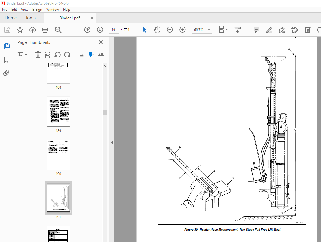
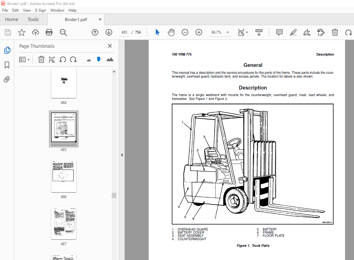
TABLE OF CONTENTS:
Yale Forklift E807 (ERP030-040TGN) Service Manual – PDF DOWNLOAD
524150790-2100YRM0103-(03-2007)-UK-EN 1
toc 1
Tilt Cylinders 1
Safety Precautions Maintenance and Repair 2
General 5
Description 5
Tilt Cylinder Repair 5
Remove 5
Disassemble 5
Clean 5
Assemble 6
Tilt Cylinders With O-Ring or Single-Lip Seals 6
Tilt Cylinders 7
Install 8
Tilt Cylinder Leak Check 10
Tilt Cylinder Stroke and Mast Tilt Angle Adjustment 11
Torque Specifications 11
Piston Rod Nut 11
Retainer 11
Troubleshooting 12
tables 1
Table 1 Movement Rates (Maximum) for Tilt Cylinders 10
524150797-8000YRM0231-(02-2023)-UK-EN 17
General 23
Threaded Fasteners 23
Nomenclature, Threads 23
Strength Identification 24
Cotter (Split) Pins 25
Fastener Torque Tables 30
Conversion Table 32
524150797-8000YRM0231-(03-2020)-UK-EN 39
General 43
Threaded Fasteners 43
Nomenclature, Threads 43
Strength Identification 44
Cotter (Split) Pins 45
Fastener Torque Tables 50
Conversion Table 52
524158040-2240YRM0001-(01-2023)-UK-EN 59
General 65
Battery Type 65
Lead-Acid Batteries 65
Lithium-Ion Batteries 66
Specific Gravity 66
Chemical Reaction in a Cell 66
Electrical Terms 68
Battery Selection 69
Battery Voltage 70
Battery as a Counterweight 70
Battery Ratings 70
Kilowatt-Hours 70
Battery Maintenance 71
Safety Procedures 71
Maintenance Records 71
New Battery 71
Cleaning Battery 72
Adding Water to Battery 74
Hydrometer 74
Battery Temperature 75
Charging Battery 76
Types of Battery Charges 77
Methods of Charging 78
Troubleshooting Charger 79
Knowing When Battery Is Fully Charged 79
Where to Charge Batteries 79
Equipment Needed 79
Battery Connectors 80
Battery Care 80
Troubleshooting 82
524158040-2240YRM0001-(03-2020)-UK-EN 87
General 91
Battery Type 91
Lead-Acid Batteries 91
Lithium-Ion Batteries 92
Specific Gravity 92
Chemical Reaction in a Cell 92
Electrical Terms 94
Battery Selection 94
Battery Voltage 95
Battery as a Counterweight 96
Battery Ratings 96
Kilowatt-Hours 96
Battery Maintenance 96
Safety Procedures 96
Maintenance Records 97
New Battery 97
Cleaning Battery 97
Adding Water to Battery 99
Hydrometer 100
Battery Temperature 101
Charging Battery 102
Types of Battery Charges 102
Methods of Charging 104
Troubleshooting Charger 104
Knowing When Battery Is Fully Charged 105
Where to Charge Batteries 105
Equipment Needed 105
Battery Connectors 106
Battery Care 106
Troubleshooting 108
524158890-4000YRM0521-(03-2006)-UK-EN 113
toc 113
Mast 113
Safety Precautions Maintenance and Repair 114
General 117
Description and Operation 117
Carriages 117
Mast Mounts 119
Two-Stage Mast, Limited Free-Lift (LFL) 120
Description and Operation 120
Two-Stage Mast, Full Free-Lift (FFL) 122
Description and Operation 122
Three-Stage Mast, Full Free-Lift (FFL) 124
Description and Operation 124
Four-Stage Mast 126
Description and Operation 126
Cylinder Cushion During Lifting Sequence 130
Cylinder Cushion During Lowering Sequence 131
524158891-4000YRM0522-(07-2010)-UK-EN 135
toc 135
Mast 135
Safety Precautions Maintenance and Repair 136
General 139
Safety Procedures When Working Near Mast 140
Fork Repair 142
Remove 142
Install 142
Carriages Repair 144
Standard Carriage, Remove 144
Hang-On Sideshift Carriage, Remove 145
Standard Carriage and Hang-On Sideshift Carriage, Repair 146
Standard Carriage, Install 147
Hang-On Sideshift Carriage, Install 148
Integral Sideshift Carriage 148
Remove 148
Clean and Inspect 152
Repair 153
Install 154
Mast Repair 155
Remove 155
Two-Stage LFL and Two-Stage FFL Masts, Disassemble 157
Three-Stage FFL Mast 165
Disassemble 165
Mast and Chains, Clean and Inspect 168
Two-Stage LFL and Two-Stage FFL Mast, Assemble 169
Three-Stage FFL Mast, Assemble 170
Install 171
Lift Cylinders Repair 173
Main Lift Cylinders, Remove 173
Free-Lift Cylinder, Remove 173
Cylinders, Disassemble 174
Two-Stage Full Free-Lift Mast, Right-Hand Main Lift Cylinder 174
Two-Stage Full Free-Lift Mast, Left-Hand Main Lift Cylinder 176
Two-Stage Limited Free-Lift Mast and Three-Stage Full Free-Lift 176
Two-Stage Limited Free-Lift Mast and Three-Stage Full Free-Lift 177
Two-Stage Full Free-Lift Mast and Three-Stage Full Free-Lift Mas 178
Clean and Inspect 179
Cylinders, Assemble 179
Two-Stage Full Free-Lift Mast, Right-Hand Main Lift Cylinder 179
Two-Stage Full Free-Lift Mast, Left-Hand Main Lift Cylinder 180
Two-Stage Limited Free-Lift Mast and Three-Stage Full Free-Lift 181
Two-Stage Limited Free-Lift Mast and Three-Stage Full Free-Lift 181
Two-Stage Full Free-Lift Mast and Three-Stage Full Free-Lift Mas 182
Main Lift Cylinders, Install 183
Free-Lift Cylinder, Install 183
Header Hose Arrangements 184
Two-Stage LFL Mast, New Hose Install 184
Two-Stage LFL Mast, Adjust Hoses After Installation 189
Two-Stage FFL Mast, New Hose Install 189
Two-Stage FFL Mast, Adjust Hoses After Installation 197
Three-Stage FFL Mast, New Hose Install 197
Three-Stage FFL Mast, Adjust Hoses After Installation 208
Header Hose Arrangement 209
Two-Stage LFL Mast, New Hose Install 209
Two-Stage LFL Mast, Adjust Hoses After Installation 214
Two-Stage FFL Mast, New Hose Install 214
Two-Stage FFL Mast, Adjust Hoses After Installation 220
Three-Stage FFL Mast, New Hose Install 220
Three-Stage FFL Mast, Adjust Hoses After Install 229
Lift and Tilt System Leak Check 230
Lift Cylinders Leak Check 230
Tilt Cylinders Leak Check 230
Tilt Cylinders Adjustment 231
Lift Chains Adjustment 233
Mast Adjustment 235
Carriage Adjustment 237
Troubleshooting 238
tables 135
Table 1 Hook-Type Carriage Chain Adjustment 233
Table 2 Pin-Type Carriage Chain Adjustment 234
524164213-1300YRM0568-(08-2005)-UK-EN 241
toc 241
Transaxle 241
Safety Precautions Maintenance and Repair 242
General 245
Lubrication 246
Transaxle Repair 246
Remove 246
Inspect 247
Install 247
S2 Series Transaxle 248
Disassemble 248
Inspection 249
Assemble 249
General 249
Ring Gear, Install 249
Intermediate Shaft, Install 249
Axle Shaft, Install 252
Pinion Gear, Install 252
Final Assembly 256
S1 Series Transaxle 257
Disassemble 257
Assemble 257
Troubleshooting 260
tables 241
Table 1 Transaxle Identification 245
Table 2 Transaxle Specifications 245
Table 3 Gear Teeth Contact Pattern 255
524164216-1800YRM0570-(08-2003)-UK-EN 263
toc 263
Brake System 263
Safety Precautions Maintenance and Repair 264
General 267
Description 267
Service Brake Pads Repair 267
Remove 267
Install 267
Service Brake Caliper Repair 269
Remove 269
Install 270
Disassemble 270
Assemble 270
Park Brake Caliper Repair 271
Remove 271
Install 272
Disassemble 272
Assemble 272
Master Cylinder Repair 272
Remove 272
Install 273
Disassemble 273
Assemble 274
Foot-Operated Park Brake Lever Assembly Repair 274
Remove 274
Install 276
Electrically Released Park Brake Repair 277
Mechanical Operation 277
Remove 277
Install 279
Electrically Released Park Brake – Electrical Components Repair 281
Control Box 281
Remove 281
Install 281
Terminal Block 283
Remove 283
Install 283
Park Brake Adjustment 285
Service Brake Adjustment 286
Brake System Air Removal 286
Troubleshooting 287
524164217-2000YRM0576-(08-2003)-UK-EN 291
toc 291
Main Control Valve 291
Safety Precautions Maintenance and Repair 292
General 295
Description 295
Operation 296
Lift Section 297
Tilt Section 297
Tilt Backward 297
Tilt Forward 297
Relief Valve 297
Main Control Valve Repair 298
Remove 298
Install 298
Disassemble 299
Clean and Inspect 301
Assemble 305
Relief Valve Check 305
Vane Settings Adjustment 306
Mast Tilt Adjustment 306
Troubleshooting 307
524164218-2200YRM0697-(08-2005)-UK-EN 313
toc 313
SX/SR Transistor Motor Controller and Handset 313
Safety Precautions Maintenance and Repair 314
Introduction to SEM 317
Advantages of Transistorized SEM 317
Features of SEM 318
Solid-State Reversing 318
Performance and Efficiency 318
Field Weakening 318
Regenerative Braking 318
SX Transistor Motor Controllers 319
Introduction 319
Proportional Operation for Dual-Motor Trucks 319
General 319
Operation 321
Controller Features 323
General 323
Creep Speed 323
Controlled Acceleration 323
Current Limit 323
Braking 323
Regenerative Braking to Zero Speed 323
Pedal Position Braking 324
Auto Braking 324
Conventional Plug Braking 324
Auxiliary Speed Control 324
Field Weakening 324
Speed Limits 324
Ramp Operation 324
Ramp Start 324
Antirollback 325
Steer Pump Contactor Time Delay 325
On-Board Coil Drivers and Internal Coil Suppression 325
System Protective Override 325
SRO (Static Return to Off) 325
Accelerator Volts Hold Off 325
Pulse Monitor Trip (PMT) 325
Thermal Protector (TP) 325
Low Voltage 325
SR Lift Pump Controllers 326
Sensor Interface/Contactor Driver Module 330
Diagnostic Status Codes and Troubleshooting 330
General Maintenance Instructions 330
Special Precautions 330
Diagnostics 331
Systems Diagnostics 331
Status Codes 331
Standard Status Codes 331
Stored Status Codes 331
Other Features 332
Hourmeter Readings 332
Maintenance Alert and Speed Limit 332
Battery Discharge Indication (BDI) 332
Internal Resistance Compensation 332
Handset Programmable 332
RS 232 Communication Ports 332
Circuit Board Coil Driver Modules 332
Maintenance Management Capability 332
Interactive Instrument Panel Modes 333
General Troubleshooting Instructions 335
Status Code Troubleshooting Tables 336
SX/SR Handset Instructions 372
General Features 372
Connecting the Handset 374
Startup Sequence 374
Setup Mode 375
Stored Status Code Mode 376
Clearing the Stored Status Codes 376
Restarting Lift Truck 376
SX Traction Controller Function Descriptions 377
Premium Instrument Panel Interactive Modes 384
SR Pump Controller Function Descriptions 386
Premium Instrument Panel Interactive Modes 389
tables 313
Table 1 SX Traction Controller Connections/Descriptions 320
Table 2 SR Lift Pump Controller Connections/Descriptions/Status 327
Table 3 Instrument Panel Function Number Correlation 333
Table 4 Traction Function Settings Logic 334
Table 5 Lift Pump Function Settings Logic 334
Table 6 Speed/Torque Compensation 388
Table 7 Traction Controller Settings – Standard With Auto Regen 391
Table 8 Traction Controller Settings – Standard Without Auto Re 392
Table 9 Traction Controller Settings – High Performance With Au 394
Table 10 Lift Pump Controller Settings 395
524164220-2200YRM0779-(08-2005)-UK-EN 399
toc 399
SR/SP Transistor Motor Controller and Handset 399
Safety Precautions Maintenance and Repair 400
Introduction to SEM 403
Advantages of Transistorized SEM 403
Features of SEM 403
Solid-State Reversing 403
Performance and Efficiency 403
Field Weakening 403
Regenerative Braking 403
SR Transistor Traction Motor Controllers 404
Introduction 404
Proportional Operation for Dual-Motor Trucks 404
General 404
Operation 406
Controller Features 408
General 408
Creep Speed 408
Controlled Acceleration 408
Current Limit 408
Braking 408
Regenerative Braking to Zero Speed 408
Pedal Position Braking 408
Auto Regenerative Braking 409
Conventional Plug Braking 409
Auxiliary Speed Control 409
Field Weakening 409
Speed Limits 409
Ramp Operation 409
Ramp Start 409
Antirollback 409
Steer Pump Contactor Time Delay 409
On-Board Coil Drivers and Internal Coil Suppression 410
System Protective Override 410
SRO (Static Return to Off) 410
Accelerator Volts Hold Off 410
Pulse Monitor Trip (PMT) 410
Thermal Protector (TP) 410
Low Voltage 410
SP Lift Pump Controllers 410
Sensor Interface/Contactor Driver Module 415
Diagnostic Status Codes and Troubleshooting 415
General Maintenance Instructions 415
Special Precautions 415
Diagnostics 416
Systems Diagnostics 416
Status Codes 416
Standard Status Codes 416
Stored Status Codes 417
Other Features 417
Hourmeter Readings 417
Maintenance Alert and Speed Limit 417
Battery Discharge Indication (BDI) 417
Internal Resistance Compensation 417
Handset Programmable 417
RS 232 Communication Ports 417
Circuit Board Coil Driver Modules 417
Maintenance Management Capability 418
Interactive Instrument Panel Modes (Premium Only) 418
General Troubleshooting Instructions 420
Status Code Troubleshooting Tables 421
Description 421
SR/SP Handset Instructions 460
General Features 460
Connecting Handset 462
Startup Sequence 463
Setup Mode 463
Stored Status Code Mode 463
Clearing Stored Status Codes 464
Restarting Lift Truck 464
SR Traction Controller Function Descriptions 465
Premium Instrument Panel Interactive Modes 471
SP Pump Controller Function Descriptions 474
Premium Instrument Panel Interactive Modes 477
tables 399
Table 1 SR Traction Controller Connections/Descriptions 405
Table 2 SP Lift Pump Controller Connections/Descriptions/Status 412
Table 3 Instrument Panel Function Number Correlation 418
Table 4 Traction Function Settings Logic 419
Table 5 Lift Pump Function Settings Logic 420
Table 6 Speed/Torque Compensation 476
524165302-0100YRM0775-(08-2003)-UK-EN 481
toc 481
Frame 481
Safety Precautions Maintenance and Repair 482
General 485
Description 485
Overhead Guard Repair 487
Remove 487
Install 488
Hood and Seat Assembly Repair 488
Remove 489
Install 489
Counterweight Repair 490
Remove 490
Install 491
Hydraulic Tank Repair 491
Inspect 491
Small Leaks, Repair 491
Large Leaks, Repair 491
Clean 491
Steam Method 492
Chemical Solution Method 492
Additional Preparations for Repair 492
Safety Labels 493
Battery Specifications 495
tables 481
Table 1 Battery Platform Weights 490
Table 2 ERP030TGN Truck Capacity 1600 kg ( 3500 lb) – Wheel Bas 495
Table 3 ERP035TGN Truck Capacity 1800 kg ( 4000 lb) – Wheel Bas 496
Table 4 ERP040TGN Truck Capacity 2000 kg ( 4400 lb) – Wheel Bas 496
524165303-1600YRM0769-(04-2002)-UK-EN 499
toc 499
Steering System 499
Safety Precautions Maintenance and Repair 500
General 503
Operation 503
Steering Wheel and Column Assembly 504
Description 504
Remove 504
Install 507
Power Steering Pump and Motor 508
Description 508
Remove 508
Install 508
Disassemble 510
Assemble 510
Steering Axle Components 512
General 512
Wheel and Tire Assembly 512
Remove 512
Install 512
Wheel Hub Assembly 512
Remove 512
Install 513
Steering Axle Assembly 513
Remove 513
Clean 514
Install 514
Steering System Air Removal 516
Operation Check 516
Steering Pressure Check 517
Troubleshooting 518
524165304-1600YRM0773-(04-2002)-UK-EN 525
toc 525
Steering Housing and Steering Control Unit 525
Safety Precautions Maintenance and Repair 526
General 529
Description 529
Operation 530
Steering Housing Repair 530
Remove and Disassemble 530
Clean 530
Assemble and Install 532
Steering Control Unit Repair 532
Remove 532
Disassemble 532
Clean 532
Assemble 534
Install 534
System Air Removal 534
Troubleshooting 535
524165305-2200YRM0774-(04-2005)-UK-EN 539
toc 539
Electrical System 539
Safety Precautions Maintenance and Repair 540
General 543
Instrument Panels 544
Standard Display 546
Premium Display 547
Replace 547
Control and Power Fuses 548
Steer Angle Potentiometer 548
General 548
Operation 548
Install 549
Positioning Steer Tire for Straight Travel 550
Adjust 550
Handset Method 550
Voltmeter Method 551
Testing 552
Power Steering Control Assembly 553
General 553
Operation 553
Testing 554
Remove and Replace 556
Power Steering Control Assembly 556
Optical Encoder 556
Lift Pump Control Board 556
Testing 563
Bypassing Lift Pump Control Board 566
Sensor Interface/Contactor Driver Module 566
General 566
Troubleshooting 568
Other Control Components 569
Key Switch 570
Seat Switch 570
Replace 570
Parking Brake Switch 571
Check 571
Replace 571
Accelerator Switch Assembly 572
Check 572
Replace 573
Direction Switches ( Foot Directional Control Pedal) 573
Check 573
Replace 573
Direction Switches (Steering Column) 574
Check 574
Replace 574
Brake Fluid Switch 574
Hydraulic Cutoff Switch 574
Check 574
Replace 575
Stop Light Switch 575
Check 576
Replace 576
Motor Temperature Switches 576
Rocker Switches for Lights 576
DC-to-DC Converter 577
Backup Light Relay Panel 577
Backup Light Switch Relay 578
Horn and Horn Button 578
Horn, Replace 578
Horn Button, Replace 579
Lights and Reverse Alarm 579
Light Assemblies Replacement 581
Tail Light 581
Flashing Light Assembly 581
Front Driving Light and Rear Work Light Assemblies 585
Spot Light Assembly 585
tables 539
Table 1 Potentiometer Specifications 552
Table 2 Power Steering Control Assembly Specifications 554
Table 3 Lift Pump Control Board Test Point/Function Relationshi 563
Table 4 Lift Pump Control Board Troubleshooting Guide 564
Table 5 Lift Pump Control Board Test Values 565
Table 6 Lift Pump Control Board Bypass Test 566
Table 7 SICDM Connections/Descriptions/Status Codes 567
524165306-8000YRM0770-(08-2005)-UK-EN 589
toc 589
Capacities and Specifications 589
Safety Precautions Maintenance and Repair 590
Wheels and Tires 593
Motors (Dual Voltage 36/48) 593
Mast Tilt Performance 593
Mast Speeds 594
Contactor Controlled 19cc/rev Displacement Pump 594
Transistor Controlled 19cc/rev Displacement Pump 595
Contactor Controlled 12cc Displacement Pump 596
Transistor Controlled 12cc/rev Displacement Pump 597
Mast/Tilt Drift Speeds 598
Hydraulic System 598
Torque Specifications 598
Frame 598
Transaxle 598
Brake System 599
Wheels 599
Steering System 599
Hydraulic System 599
Mast/Tilt/Attachment Systems 599
Accelerator Potentiometer Checks 600
Controller Settings 600
SR/SP Traction Controller Settings – Standard 600
SR/SP Traction Controller Settings – 36 V Energy Saver Option 602
SR/SP Traction Controller Settings – With or Without Auto Decele 602
SR/SP Traction Controller Settings – With or Without Lift Limit 602
SR/SP Lift Pump Controller Settings 603
Battery Size Specifications 604
Type: Lead Acid Battery 604
524165307-8000YRM0771-(02-2007)-UK-EN 607
toc 607
Diagrams 607
Safety Precautions Maintenance and Repair 608
524165308-8000YRM0772-(08-2003)-UK-EN 641
toc 641
Periodic Maintenance 641
Safety Precautions Maintenance and Repair 642
General 645
How to Move Disabled Lift Truck 645
How to Tow Lift Truck 645
How to Put Lift Truck on Blocks 646
How to Raise Drive Tires 646
How to Raise Steer Tires 647
Maintenance Schedule 648
Maintenance Procedures Every 8 Hours or Daily 652
Before Operation Checks 652
Hydraulic System 652
Battery 653
Battery Restraint System 653
Tires and Wheels 654
Safety Procedures When Working Near Mast 655
Forks 657
Adjust 657
Remove 658
Inspect 658
Install 658
Mast and Lift Chains 659
Lift Chain, Adjustment 660
Operation Check 661
Gauges and Horn 661
Control Levers and Pedals 661
Service Brakes 661
Parking Brake 661
Steering System 661
Maintenance Procedures Every 350 Hours or 3 Months 662
Hydraulic Tank Breather 662
Wheel Nut Torque 662
Steering Actuator Mounting Bolts 662
Transaxle 662
Lift System Operation 663
Mast 663
Lift Chains 665
Forks 665
Safety Labels 666
Brake Fluid 666
Other Lubrication 666
Electrical Inspection 666
Special Precautions 666
Contactors 667
Motor Brushes 667
Parking Brake 667
Maintenance Procedures Every 2000 Hours or Yearly 674
Hydraulic System 674
Hydraulic Oil Filter, Change 674
Hydraulic Oil Strainer, Check 674
Hydraulic Oil, Change 674
Brakes 675
Parking Brake, Adjust 675
Transaxle 676
Maintenance Procedures Every 4000 Hours 677
Transaxle 677
Lift and Tilt System Leak Check 677
Lift System 677
Tilt System 678
Battery Maintenance 678
How to Charge Battery 678
How to Change Battery 679
Battery Size Specifications 680
Wheels and Tires Maintenance 681
General 681
How to Change Tires 681
Steer and Drive Wheels 681
Pneumatic Tires 681
Remove Wheel From Lift Truck 681
Tire Sizes and Pressures 682
Remove Tire From Wheel 683
Install Tire on Wheel 684
Add Air to Tires 685
Pneumatic-Shaped Solid Tires 685
Remove Wheel From Lift Truck 685
Press Tire From Wheel 686
Install Tire on Wheel 687
Install Wheel and Tire 689
tables 641
Table 1 Maintenance Schedule 649
Table 2 Transaxle Specifications 676
Table 3 Battery Size Specifications – Type: Lead-Acid Battery 680
524167640-2200YRM0947-(08-2007)-UK-EN 693
toc 693
Troubleshooting and Adjustments With a Computer 693
Safety Precautions Maintenance and Repair 694
Computer System 697
Connect a PC to a Control Card 698
Installation 699
SMARTSET™ Windows Software Program 699
How to Start the Program 699
DEMO Mode 700
Selecting the Communications Port 702
Verification of Controller and Lift Truck 703
Select Lift Truck Series 705
Controller Card Register Parameter List 706
How to Change a Parameter 707
How to Save a Changed Parameter File 708
How to Load a Saved Parameter File 710
How to Show and Remove Saved Parameter Files 710
How to Return to Factory Default Settings 711
How to Save Changes to Control Card 712
How to View Status Codes 713
Saving Status Codes 714
How to Show and Remove Saved Status Code Files 715
Closing and Clearing Status Code List 716
How to View Saved Register Data and Saved Status Data 717
How to Save Register Data and Status Code Data In RTF and TXT 719
GE Sentry™ Software Program 720
Installation 720
Description 720
How to Start GE SENTRY Program 720
How to Reset MIN and MAX Display 725
Graphing Mode 726
How to Exit GE SENTRY Program 727
tables 693
Table 1 Cable Connections – Computer to Control 697
Table 2 Adapter Pins (DB25F to DB9) 698
Table 3 Plug-Z Connection 699
524201833-2000YRM1071-(08-2003)-UK-EN 731
toc 731
HUSCO™ Main Control Valve 731
Safety Precautions Maintenance and Repair 732
General 735
Description 735
Operation 735
Lift Section 738
Tilt Section 738
Tilt Backward 738
Tilt Forward 738
Relief Valve 740
Main Control Valve Repair 741
Remove 741
Disassemble 746
Clean and Inspect 746
Assemble 746
Install 746
Pressure Relief Valve Check and Adjustment 749
Primary Relief Valve 749
Secondary Relief Valve 749
Vane Settings Adjustment 750
Troubleshooting 750
More products