$41.95
Yale Forklift E813 (GDPGLP35-40LJ, GDPGLP45-55 MJ Europe) Service Manual PDF
Yale Forklift E813 (GDPGLP35-40LJ, GDPGLP45-55 MJ Europe) Service Manual – PDF DOWNLOAD
FILE DETAILS:
Yale Forklift E813 (GDPGLP35-40LJ, GDPGLP45-55 MJ Europe) Service Manual – PDF DOWNLOAD
Language : English
Pages : 1664
Downloadable : Yes
File Type : PDF
PART NO. 524150791
IMAGES PREVIEW OF THE MANUAL:
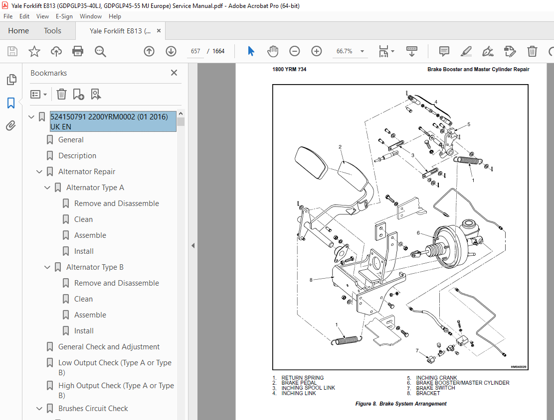
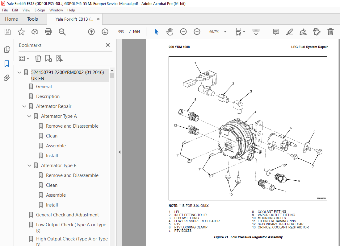
TABLE OF CONTENTS:
Yale Forklift E813 (GDPGLP35-40LJ, GDPGLP45-55 MJ Europe) Service Manual – PDF DOWNLOAD
524150791 2200YRM0002 (01 2016) UK EN 1
General 5
Description 6
Alternator Repair 8
Alternator Type A 8
Remove and Disassemble 8
Clean 10
Assemble 10
Install 11
Alternator Type B 14
Remove and Disassemble 14
Clean 14
Assemble 15
Install 16
General Check and Adjustment 16
Low Output Check (Type A or Type B) 17
High Output Check (Type A or Type B) 20
Brushes Circuit Check 21
Delco Alternators 21
Motorola Alternators 21
Diodes Check 22
Diode Bridge Check 22
Delco and Leece-Neville Alternators 22
Motorola Alternators 22
Rotor Field Winding Check 23
Stator Windings Check 24
Voltage Regulator Check 24
Troubleshooting 24
524150797 8000YRM0231 (02 2023) US EN 29
General 35
Threaded Fasteners 35
Nomenclature, Threads 35
Strength Identification 36
Cotter (Split) Pins 37
Fastener Torque Tables 42
Conversion Table 44
524150797 8000YRM0231 (03 2020) UK EN 51
General 55
Threaded Fasteners 55
Nomenclature, Threads 55
Strength Identification 56
Cotter (Split) Pins 57
Fastener Torque Tables 62
Conversion Table 64
524153601 1300YRM0800 (03 2004) UK EN 71
toc 71
Hydrostatic Transmission 71
Safety Precautions Maintenance and Repair 72
General 75
Component Descriptions 75
Power Unit General Arrangement 75
Hydrostatic Pump Mounting 76
Perkins 1004-42 and 1104C-44(RE) Diesel Engines 76
GM 4 3L LPG Engine 76
Hydrostatic Control Components 76
Hydrostatic System Operation 79
Hydrostatic Pump 79
Drive Axle 80
Transmission Control Module (TCM) 81
Perkins 1004-42 Diesel Engine Trucks 81
Perkins 1104C-44(RE) Diesel and GM 4 3L LPG Engine Trucks 82
Transmission Control Inputs 82
Key Switch 82
Forward/Reverse Switches, Perkins 1004-42 Diesel Engine Trucks 82
Forward/Reverse Switches, Perkins 1104C-44(RE) Diesel and GM 4 3 82
Parking Brake Switches 85
Engine Speed Sensor 85
Wheel Speed Sensors, Perkins 1104C-44(RE) Diesel and GM 4 3L LPG 85
Brake Pressure Sensor 85
Charge Pressure Sensor 85
Transmission Oil Temperature Sensor 85
Throttle Pedal Switch, Perkins 1004-42 Diesel Engine Trucks 85
Throttle Pedal Switch, Perkins 1104C-44(RE) Diesel and GM 4 3L L 88
Throttle Pedal Position Sensor, Perkins 1004-42 Diesel Engine Tr 88
Throttle Pedal Position Sensor, Perkins 1104C-44(RE) Diesel and 88
Transmission Control Outputs 88
Forward/Reverse Solenoid Enable, Perkins 1004-42 Diesel Engine T 88
Forward/Reverse Solenoid Enable, Perkins 1104C-44(RE) Diesel and 88
Forward/Reverse Solenoids, Perkins 1104C-44(RE) Diesel and GM 4 90
Engine Start Enable 90
Fuel Cutoff Relay 90
Retard Valve 90
Pilot Solenoid Valve, Perkins 1004-42 Diesel Engine Trucks 90
Pilot Solenoid Valve Enable, Perkins 1104C-44(RE) Diesel and GM 90
Transmission Fault Warning Light 90
Transmission Overspeed Warning Light 92
Oil Temperature Warning Light 92
Throttle-Up Inputs 92
Lift Lever Switch, Perkins 1004-42 Diesel Engine Trucks 92
Lift Lever Position Sensor, Perkins 1004-42 Diesel Engine Trucks 93
Lift Lever Switch, Perkins 1104C-44(RE) and GM 4 3L LPG Engine T 93
Lift Lever Position Sensor, Perkins 1104C-44(RE) and GM 4 3L LPG 93
Tilt/Auxiliary Lever Switches, Perkins 1004-42 Diesel Engine Tru 93
Tilt/Auxiliary Lever Switches, Perkins 1104C-44(RE) Diesel and G 93
Engine Throttle Position Sensor, Perkins 1004-42 Diesel Engine T 93
Throttle-Up Outputs, Perkins 1004-42 Diesel Engine Trucks 93
Throttle-Up Motor 93
Throttle Servo Motor – Perkins 1104C-44(RE) Diesel and GM 4 3L L 94
Transmission Control Module (TCM) Operation 95
How the TCM Begins Operation 95
TCM Operation on a Running Lift Truck 95
Lift Trucks With Perkins 1004-42 Diesel Engine 95
Lift Trucks With Perkins 1104C-44(RE) Diesel and GM 4 3L LPG Eng 95
Event and Fault Detection 95
Diagnostic Connector 96
Hydrostatic Transmission Features 96
Travel Control 96
Lift Trucks With The Perkins 1004-42 Diesel Engine 96
Lift Trucks With the Perkins 1104C-44(RE) Diesel and GM 4 3L LPG 96
Antistall 97
Dynamic Braking 97
Brake Inching 97
Overspeed Control 97
Hydraulic Retard 98
Wheel Anti-spin 98
Temperature Compensation 98
Low Charge Pressure Compensation 99
Quick-Roll 100
Throttle-Up (Option) 100
Perkins 1004-42 Diesel Engine Lift Trucks Only 100
Hydraulic Circuit 100
Loop Circuit 100
Charge Circuit 103
Pilot Supply Circuit 103
Pilot Control Circuit 103
Retard Circuit 103
Cooling Oil Supply Circuit 104
Cooling Circuit 104
tables 71
Table 1 Electronic Transmission Control System – Perkins 1004-4 78
Table 2 Electronic Transmission Control System – Perkins 1104C- 78
524153606 1300YRM0801 (03 2004) UK EN 107
toc 107
Hydrostatic Transmission 107
Safety Precautions Maintenance and Repair 108
General 113
TransLink™ User Interface Software 113
Connecting PC to TCM 113
Transmission Fluid 114
Startup and Calibration 116
Startup Procedure Following Service or Repairs 116
Throttle System Calibration 117
Perkins 1004-42 Diesel Engine 117
Perkins 1104C-44(RE) Diesel Engine and GM 4 3L LPG Engine 118
Throttle System Calibration Checks 118
Perkins 1104C-44(RE) Diesel Engine and GM 4 3L LPG Engine Lift T 118
Hydrostatic Pump Repair 118
Remove 118
Install 122
Charge Pump Repair 122
Remove 122
Inspect 123
Install 123
Pump Control Valve Repair 125
Remove 125
Inspect 125
Install 125
Replace Pilot Solenoid 125
Replace Directional Solenoid Pair 125
Clean or Replace Pilot Supply Filter Disk 125
Replace Loop Relief Cartridges 126
Replace Filter Cartridge 126
Replace Filter Head 127
Drive Axle Repair 127
Remove and Disassemble 127
Inspect 130
Assemble and Install 130
Wheel Speed Sensors, Replace 131
Lift Trucks With Perkins 1104C-44(RE) Diesel Engine and GM 4 3L 131
Axle Valve Repair 131
Remove 131
Inspect 131
Install 131
Replace Pressure Reducing Valve 131
Replace Shuttle Valve 132
Replace Charge Supply Regulator 132
Replace Retard Valve 132
Replace Temperature Sensor 132
Transmission Control Module (TCM) Replacement 133
Throttle Pedal/ Foot Directional Control Pedal Repair 133
Remove Standard Throttle Pedal 133
Install Standard Throttle Pedal 133
Lift Trucks With Perkins 1004-42 Diesel Engine 133
Lift Trucks With Perkins 1104C-44(RE) Diesel Engine and GM 4 3L 133
Remove and Disassemble Foot Directional Control Pedal 134
Assemble and Install Foot Directional Control Pedal 134
Replace Throttle Pedal Position Sensor 137
Replace Throttle Pedal Switch 137
Throttle-Up Assembly Replace – Perkins 1004-42 Diesel Engine 138
Remove 138
Inspect 138
Install 138
Replace Throttle Motor 139
Replace Engine Throttle Position Sensor 139
Throttle Servo Motor Replace – Perkins 1104C-44(RE) Diesel and G 139
Remove 139
Perkins 1104C-44(RE) Diesel Engine 139
GM 4 3L LPG Engine 139
Inspect 141
Install 141
Perkins 1104C-44(RE) Diesel Engine 141
GM 4 3L LPG Engine 141
Throttle-Up Switch Assembly Repair 143
Remove 143
Install 143
Replace Lift Lever Position Sensor 143
Replace Throttle-Up Switches 143
Hydrostatic Drive Checks and Adjustments 144
Swashplate Positioning Cylinder 144
Truck Travel Speed Limit Adjustment 145
Perkins 1004-42 Diesel Engine 145
Perkins 1104C-44(RE) Diesel Engine and GM 4 3L LPG Engine 145
Charge Pressure 145
Pilot Supply Pressure 146
Pilot Pressure 146
POR Pressure 146
Loop Pressure 146
Throttle Pedal/ Foot Directional Control Pedal Checks and Adjust 147
Throttle Cable 147
Perkins 1004-42 Diesel Engine Trucks 147
Pedal Stop 147
Standard Throttle Pedal 147
Perkins 1004-42 Diesel Engine Trucks 147
Perkins 1104C-44(RE) Diesel and GM 4 3L LPG Engine Trucks 147
Foot Directional Control Pedal 147
Perkins 1004-42 Diesel Engine Trucks 147
Perkins 1104C-44(RE) Diesel and GM 4 3L LPG Engine Trucks 147
Foot Directional Control Pedal Operation 148
Throttle Pedal Position Sensor 148
Throttle Pedal Switch 148
Foot Directional Control Pedal Switch 149
Throttle-Up Assembly Checks and Adjustments 150
Engine Throttle Position Sensor 150
Throttle-Up Motor 151
Throttle Servo Motor Checks and Adjustments 151
Throttle Servo Motor Position Sensor 151
Throttle Servo Motor 152
Throttle-Up Switch Assembly Checks and Adjustments 153
Throttle-Up Switches 153
Lift Lever Position Sensor 153
Sensor Checks 154
Charge Pressure Sensor 154
Brake Pressure Sensor 154
Oil Temperature Sensor 155
Engine Speed Sensor 155
Left Speed Sensor 156
Right Speed Sensor 157
Event Codes 157
Perkins 1004-42 Diesel Engine Trucks 157
Event Code Descriptions – Perkins 1004-42 Diesel Engine Trucks 158
Perkins 1104C-44(RE) Diesel Engine and GM 4 3L LPG Trucks 164
Event Code Descriptions – Perkins 1104C-44(RE) Diesel and GM 4 3 165
Troubleshooting 173
Perkins 1004-42 diesel engine trucks only 177
Perkins 1004-42 diesel engine trucks only 178
Perkins 1104C-44(RE) diesel and GM 4 3L LPG engine trucks 179
Perkins 1104C-44(RE) diesel and GM 4 3L LPG engine trucks 179
tables 107
Table 1 Charge and Brake Sensor Outputs 155
Table 2 Oil Temperature Sensor Outputs 155
Table 3 Engine Speed Sensor Outputs 156
Table 4 Wheel Speed Sensor Outputs – Perkins 1104C-44(RE) Diese 156
524153897 0600YRM0590 (04 2014) UK EN 183
524153904 1600YRM0732 (10 2003) UK EN 235
toc 235
Steering Control Unit 235
Safety Precautions Maintenance and Repair 236
General 239
Description 239
Operation 239
Steering Wheel and Column Assembly Repair 241
Remove and Disassemble 241
Assemble and Install 241
Steering Control Unit 244
Disassemble 244
Clean 246
Assemble 247
System Air Removal 250
Troubleshooting 250
524153909 1900YRM0743 (06 2005) UK EN 255
toc 255
Hydraulic System 255
Safety Precautions Maintenance and Repair 256
General 259
Description 259
Operation 261
Hydraulic Pump GLP/GDP 3 5-5 5LJ/MJ (GP/GLP/GDP70-120LJ/MJ) 261
Hydraulic Pump GC070-120LJ/MJ 261
Main Control Valve 261
Steering Control Unit 262
Specifications 262
Hydraulic System Capacity (Powershift) 262
Hydraulic System Capacity (Hydrostatic) 262
Hydraulic Tank Capacity (Powershift and Hydrostatic) 263
Hydraulic Tank Capacity 263
Relief Pressures @ 2200 RPM, 50 to 80 C ( 120 to 180 F) 263
Hydraulic Pump Flow to Valve 263
Steering Priority Flow 263
Troubleshooting 263
Lift, Lower and Tilt Circuit 264
Steering Circuit 265
524153910 2000YRM0754 (12 2003) UK EN 269
toc 269
Main Control Valve 269
Safety Precautions Maintenance and Repair 270
General 273
Description 273
Operation 273
Lift Section 273
Tilt and Auxiliary Sections 277
Reattaching the Clevis End of the Tilt Spool 278
Relief Valve 278
Main Control Valve Repair 278
Remove and Disassemble 278
Clean and Inspect 280
Assemble 282
Install 282
Pressure Relief Valve Check and Adjustment 283
Main Relief Valve (Lift) 283
Steering Relief Valve 283
Secondary Relief Valve (Tilt and Auxiliary) 286
Specifications 287
Troubleshooting 287
524153913 2200YRM0755 (10 2003) UK EN 293
toc 293
Starter 293
Safety Precautions Maintenance and Repair 294
General 297
Description 297
Yoke Assembly 298
Armature Assembly 298
Clutch Assembly 298
Magnetic Switch Assembly 298
Operation 298
Starter Repair 299
Remove 299
Disassemble 300
Clean 303
Assemble 304
Install 307
General Checks and Adjustments 307
Armature Tests 308
Armature Short Circuit Test 308
Armature Winding Ground Test 308
Commutator Run-Out Test 308
Yoke Test 309
Brush and Brush Holder Check 309
Brush Holder Insulation Test 309
Clutch Test 309
Magnetic Switch Test 310
Pull-In Test 310
Hold-In Test 310
Return Test 310
Performance Tests 311
No-Load Test 311
Troubleshooting 311
524153915 2200YRM0756 (02 2007) UK EN 317
toc 317
Instrument Panel Indicators and Senders 317
Safety Precautions Maintenance and Repair 318
General 321
Description 321
Instruments and Senders 321
Password Function 327
Supervisor Password Function 327
Entering Operator Passwords 327
Deleting Operator Passwords 328
Retrieve the Most Recent Operator Password Used to Enable the Tr 328
Display All Operator Passwords Programmed Into the System 328
Enable and Disable Operator Passwords Function 328
Allow Supervisor Password to Enable the Truck to Start 328
Operator Passwords Function 328
Component Replacement – General Information 329
Sender Replacement 329
Fuel Level Sender 329
Pressure and Temperature Sender 330
Seat Sensor, Operator Presence System (OPS) 331
Remove 331
Install 331
Operator Presence System Module Replacement 331
Remove 331
Install 333
Display Panel Replacement 334
Specifications 336
Troubleshooting 337
Troubleshooting For Operator Presence System GP/GLP/GDP70-120LJ/ 338
Troubleshooting For Operator Presence System GC70-120LJ/MJ (C818 340
tables 317
Table 1 Instrument Panel Description 322
Table 2 Sender Description 326
Table 3 Meter and Sender Specifications 336
Table 4 Troubleshooting Procedure for the Operator Presence Mod 338
Table 5 Troubleshooting Procedure for the Operator Presence Mod 340
524153919 4000YRM0741 (03 2005) UK EN 345
toc 345
Lift Cylinders 345
Safety Precautions Maintenance and Repair 346
Safety Procedures When Working Near Mast 349
General 351
Description 351
Lowering Control Valve (Velocity Fuse) 351
Lift Cylinder Repair 354
Remove 354
Disassemble 355
Assemble 355
Install 355
Lift System Leak Check 356
Troubleshooting 357
524153920 4000YRM0736 (07 2010) UK EN 361
toc 361
Masts 361
Safety Precautions Maintenance and Repair 362
General 365
Description and Operation 365
Carriages 365
Two-Stage Mast With Limited Free-Lift 365
Two-Stage Mast With Full Free-Lift 366
Three-Stage Mast With Full Free-Lift 367
Safety Procedures When Working Near Mast 369
Fork Replacement 371
Remove 372
Install 372
Carriage Repair 373
Remove 373
Sideshift Carriage Repair 375
Remove 375
Disassemble 375
Assemble 375
Install 375
Two-Stage Mast With Limited Free-Lift Repair 377
Remove, GLP/GDP3 5-5 5LJ/MJ (GP/GLP/GDP070-120LJ/MJ) Model Lift 377
Remove, GC070-120LJ/MJ, ERC070-120HG (A839), and ERC35-55HG (ERC 379
Disassemble 382
Clean and Inspect 382
Assemble 383
Install, GLP/GDP3 5-5 5LJ/MJ (GP/GLP/GDP070-120LJ/MJ) Lift Truck 384
Install, GC070-120LJ/MJ, ERC070-120HG (A839), and ERC35-55HG (ER 386
Two-Stage Mast With Full Free-Lift Repair 388
Remove 388
Disassemble 388
Clean and Inspect 390
Assemble 390
Install 390
Three-Stage Mast With Full Free-Lift Repair 392
Remove 392
Disassemble 392
Clean and Inspect 396
Assemble 396
Install 397
Mast Operation Check 403
Lift and Tilt System Leak Check 404
Lift System 404
Tilt System 405
Tilt Cylinder Stroke and Backward Tilt Angle Adjustment 406
Lift Chain Adjustments 408
Mast Adjustments 410
Carriage Adjustment 412
Troubleshooting 413
tables 361
Table 1 Tilt Cylinder Leak Check Specifications, GC070-120LJ/MJ 405
Table 2 Hook-Type Carriage Chain Adjustment 408
Table 3 Pin-Type Carriage Chain Adjustment 409
524173800 0100YRM0726 (02 2007) UK EN 419
toc 419
Frame 419
Safety Precautions Maintenance and Repair 420
General 423
Description 423
Counterweight Repair 423
Remove 423
Install 424
Hood Repair 424
Remove 424
Install 424
Overhead Guard Repair 426
Remove 426
Inspect 426
Install 426
LED Backup and Brake Lights, Replace 426
Remove 426
Install 426
Operator Restraint System Repair 427
Automatic Locking Retractor (ALR) 427
Emergency Locking Retractor (ELR) 428
Radiator Repair 429
Remove 429
Install 429
Exhaust System Repair 431
Muffler 431
Remove 431
Install 431
LPG/Gas Engine Exhaust Pipe – Lift Trucks Without Low Emissions 434
Remove 434
Install 434
EPA Compliant LPG/Gas Engine Exhaust System 434
Remove 434
Install 436
Diesel Engine Exhaust Pipe 436
Remove 436
Install 438
Engine Repair 438
Remove 438
Install 440
Throttle Pedal Adjustment 442
Perkins 1104C-44(RE) Diesel Engine 442
Lift Trucks With an Accelerator Pedal 442
Lift Trucks With a Foot Directional Control Pedal 443
Fuel and Hydraulic Tanks Repair 445
Inspect 445
Small Leaks, Repair 445
Large Leaks, Repair 445
Clean 445
Steam Method 445
Chemical Solution Method 445
Other Preparation Methods for Repair 446
Safety Labels 446
tables 419
Table 1 Weight of Counterweights 423
524173801 0100YRM0778 (06 2004) UK EN 451
toc 451
Operators Cab 451
Safety Precautions Maintenance and Repair 452
General 455
Cab Repair 456
Remove 456
Install 457
Switch Panel 457
Window Wipers Replacement 458
Front Wiper Assembly 458
Rear Wiper Assembly 458
Door Handle Assembly 460
Fuse Panel 461
Heater Assembly 461
Remove 461
Install 461
Window Replacement 463
Options 465
Rear Strobe Lights 465
Heavy-Duty Air Cleaner 465
Label Replacement 466
Electrical Schematics 466
tables 451
Table 1 Material Specifications for Cab Windows 463
524173802 0700YRM0740 (02 2004) UK EN 471
toc 471
Cooling System 471
Safety Precautions Maintenance and Repair 472
General 475
Description 475
Radiator 475
Radiator Cap 475
Thermostat 475
Water Pump 476
Fan and Fan Shroud 476
Drive Shaft 476
Cooling System Checks 476
Exhaust Leaks into Cooling System 476
Radiator Repair 476
Checks 476
Clean 476
Cooling System 478
Drain 478
Fill 478
Water Pump Repair 478
Checks 478
Thermostat Repair 479
Checks 479
Fan Assembly Repair 479
Remove 479
Inspect 479
Install 479
Fan Belt Repair 482
Remove 482
Install 482
Drive Shaft Repair 482
Remove 482
Install 482
Troubleshooting 482
524173803 0900YRM0745 (09 2003) UK EN 487
toc 487
LPG Fuel System 487
Safety Precautions Maintenance and Repair 488
General 491
Description and Operation 491
Fuel Tank 491
Fuel Filter and Fuel Valve Unit 491
LPG Convertor Vaporizer (IMPCO) 491
LPG Controller (Dana EPIC/Teleflex-GFI) 495
Filter Section 495
Lock-Off Section 495
Converter Section – Primary Regulation (Stage 1) 495
Converter Section – Secondary Regulation (Stage 2) 495
Carburetor 496
Governor 499
Two-Way Valves, Open-Loop System 499
Closed-Loop Fuel Control 499
O E Tune Valve, Closed-Loop Fuel System 500
Oxygen Sensor, Closed-Loop Fuel System 500
LPG Tank Repair 500
Remove 500
Install 500
Hydrostatic Relief Valve Repair 501
Remove and Install 501
Filter Unit Repair 502
Fuel Filter Element, Replace 502
Diaphragm and Fuel Valve, Replace 502
Hoses Replacement 502
LPG Convertor Vaporizer (IMPCO) Repair 504
Remove 504
Disassemble 504
Clean 504
Inspect 504
Assemble 506
Install 510
LPG Controller (Dana EPIC/Teleflex-GFI) Repairs 510
Remove 510
Disassemble 510
Converter Section 510
Filter Section 512
Lock-Off Section 512
Clean 514
Inspect 514
LPG Controller Assembly 514
Filter Section 514
Lock-Off Section 514
Converter Section 514
Carburetor Repair 516
Remove 516
Disassemble 516
Clean 516
Assemble 517
Install 517
Governor Assembly Repair 518
Governor Motor Repair 520
Remove 520
Install 520
Filter Unit Check 520
Vaporizer Check 521
Pressure Reducer Valve 521
Vapor Valve 521
Carburetor Adjustment 521
Idle Mixture 521
Idle Speed 521
Throttle Linkage Adjustment 521
LPG Controller Adjustments (Dana EPIC/Teleflex-GFI) 522
Filter and Lock-Off Sections Leak Check 522
Lock-Off Section Functional Check 523
Controller Pressure Test 523
Adjustment of Secondary Lever 524
Final Adjustment Check 524
Troubleshooting 525
524173804 1300YRM0727 (06 2004) UK EN 535
toc 535
Two-Speed Powershift Transmission 535
Safety Precautions Maintenance and Repair 536
General 539
Mechanical Description 539
Torque Converter 540
Transmission Pump 540
Shaft Assemblies 540
Input (Reverse) Shaft 540
Counter (Forward) Clutch Shafts 540
Clutch Assemblies 540
Output Gear and Pinion 541
Electronic Control Unit 541
Hydraulic Operation 542
Torque Converter 542
Seal Rings 543
Control Valve 543
Clutch Pressure Regulator 543
Inching Spool Assembly 543
Direction Spool 545
Modulator Circuit 545
Torque Converter Regulator 545
Foot Directional Control Pedal 546
Foot Directional Control Pedal Start Circuit 546
Direction Control Lever 547
Oil Flow Diagrams 547
Neutral 548
Modulator Operation 549
Forward-Low 551
Forward-Low-Inching 551
Reverse 557
524173805 1300YRM0728 (08 2006) UK EN 565
toc 565
Two-Speed Powershift Transmission 565
Safety Precautions Maintenance and Repair 566
General 569
Transmission Repair 569
Remove 569
Install 569
Clutch Packs Repair 572
Remove and Disassemble 572
Clutch Assemblies, Disassemble 575
Inspect 577
Assemble and Install 578
Clutch Assemblies, Assemble and Install 578
Differential Repair 586
Remove and Disassemble 586
Inspect 587
Original Parts, Assemble and Install 587
New Parts, Assemble and Install 587
Adjustments With Original Shim Pack 588
Adjustments Without Original Shim Pack 589
Differential and Ring Gear Assembly, Assemble 591
Control Valve Repair 596
Remove and Disassemble 596
Inspect 598
Assemble and Install 598
Foot Directional Control Pedal Repair 599
Remove and Disassemble 599
Assemble and Install 599
Direction Control Lever 602
Remove and Disassemble 602
Assemble and Install 602
Stall Test 603
Inching/Brake Pedal Adjustment 604
Foot Directional Control Pedal Neutral Start Switch Adjustment 606
Foot Directional Control Pedal Neutral Start Switch Test 607
Test 1 607
Test 2 607
Electronic Control Unit Check 608
Oil Pressure Check 609
Transmission Pump Relief Valve, Test Port 1, Check 610
Input (Reverse) Clutch Pressure, Test Port 2, Check 610
Counter (Forward) Clutch Pressure, Test Ports 3 and 4, Check 610
Torque Converter Regulator, Test Port 5, Check 610
Lubrication Circuit Oil Pressure, Test Port 6, Check 610
Modulator Pressure, Test Port 7, Check 610
2-Speed Transmission Will Not Shift 611
Troubleshooting 612
Troubleshooting – Pressure Tests 615
tables 565
Table 1 Pinion Variation Numbers Examples 588
Table 2 Ring and Pinion Tooth Contact Adjustment 594
Table 3 Stall Speeds (New Engines) 603
Table 4 Electronic Control Unit Connector 608
Table 5 Transmission Pressure Port Check 609
524173806 1400YRM0731 (09 2003) UK EN 619
toc 619
Drive Axle 619
Safety Precautions Maintenance and Repair 620
General 623
Description 623
Drive Axle Repair 623
Remove and Disassemble 623
Clean and Inspect 625
Assemble and Install 625
Troubleshooting 627
524173807 1600YRM0733 (09 2003) UK EN 631
toc 631
Steering Axle 631
Safety Precautions Maintenance and Repair 632
General 635
Description 635
Steering Axle Assembly Repair 636
Remove 636
Install 636
Wheels and Hub Repair 637
Remove and Disassemble 637
Clean 637
Inspect 637
Assemble and Install 637
Spindles and Bearings Repair 638
Remove 638
Clean 638
Inspect 638
Assemble and Install 638
Tie Rods Repair 639
Remove 639
Clean 639
Inspect 639
Install 639
Steering Cylinder Repair 639
Remove and Disassemble 639
Clean and Inspect 639
Assemble and Install 640
Troubleshooting 641
524173808 1800YRM0734 (05 2005) UK EN 645
toc 645
Brake System 645
Safety Precautions Maintenance and Repair 646
General 649
Description and Operation 649
Brake Booster and Master Cylinder 649
Service Brake Assembly 649
Parking Brake 649
Brake Shoe Assemblies Repair 650
Remove and Disassemble 650
Clean 652
Inspect 652
Assemble and Install 653
Brake Booster and Master Cylinder Repair 656
Remove 656
Disassemble 656
Clean and Inspect 656
Assemble 656
Install 656
Brake Booster Filter, Replace 656
Parking Brake Repair 659
Remove and Disassemble 659
Assemble and Install 659
Brake System Air Removal 659
Brake Pedal Adjustment 659
Parking Brake Adjustment 660
Parking Brake Not Applied Switch Test 660
Parking Brake Switch Test ( Foot Directional Control Pedal Only) 661
Brake Shoes Adjustment 661
Troubleshooting 662
524173809 1900YRM0753 (09 2003) UK EN 667
toc 667
Hydraulic Gear Pump 667
Safety Precautions Maintenance and Repair 668
General 671
Description 671
Operation 671
Hydraulic Gear Pump Repair 672
Remove 672
Disassemble 672
Clean 674
Inspect 674
Assemble 675
Install 675
Pump Output Check 676
Method No 1 676
Method No 2 677
Hydraulic System Air Check 678
Troubleshooting 678
524173810 2100YRM0735 (11 2004) UK EN 683
toc 683
Tilt Cylinders 683
Safety Precautions Maintenance and Repair 684
General 687
Description 687
Tilt Cylinder Repair 687
Remove 687
Disassemble 688
Clean 689
Inspect 689
Assemble 689
Install 689
Tilt Cylinder Leak Check 690
Tilt Cylinder Stroke and Mast Tilt Angle Adjustment 690
Troubleshooting 690
524173811 2200YRM0744 (09 2003) UK EN 695
toc 695
Carbureted Engine Management System (CEMS) 695
Safety Precautions Maintenance and Repair 696
Description 699
Ignition Control System 700
Setting Timing Reference 700
Idle Speed Control System 700
Curb Idle Setting Procedure 700
Governor Control System 701
Closed-Loop Fuel System 702
Closed-Loop Fuel Control 702
Entering Closed-Loop Control 702
Normal Closed-Loop Operation 702
Closed-Loop Diagnostics 702
O E Tune Valve Action at Engine Shutdown 702
Diagnostic System 703
Closed-Loop Diagnostic Troubleshooting 704
Diagnostic Troubleshooting 704
tables 695
Table 1 Diagnostic Codes 703
Table 2 Diagnostic Troubleshooting 704
524173814 8000YRM0737 (03 2011) UK EN 711
toc 711
Periodic Maintenance 711
Safety Precautions Maintenance and Repair 712
General 717
Serial Number Data 717
How to Move Disabled Lift Truck 717
How to Tow Lift Truck 717
How to Put Lift Truck on Blocks 718
How to Raise Drive Tires 718
How to Raise Steering Tires 718
Maintenance Schedule 719
Maintenance Procedures Every 8 Hours or Daily 731
How to Make Checks With Engine Stopped 731
Engine Oil 732
Hydraulic System Oil 732
Cooling System 733
Heavy Duty Precleaner 733
Fuel System 733
Battery 734
Tires and Wheels 734
Forks 735
Adjust 735
Hook Fork, Remove 736
Hook Fork, Install 736
Forks, Mast, and Lift Chains, Inspect 737
Operator Restraint System 737
Automatic Locking Retractor (ALR) 737
Emergency Locking Retractor (ELR) 737
Safety Labels 739
How to Make Checks With Engine Running 739
Gauges, Lights, Horn, and Fuses 739
Engine Oil Pressure 740
Cooling System 742
Powershift Transmission Oil Level Check 742
Hydrostatic Transmission Oil Level Check 743
Control Levers and Pedals 743
Lift System Operation 743
Inching/Brake Pedal 743
Service Brakes 744
Parking Brake 744
Steering System 744
Maintenance Procedures Every 250 Hours or 6 Weeks 745
Engine Oil and Filter, GM V-6 EPA Compliant Engine (Americas Onl 745
Air Filter, GM V-6 EPA Compliant Engine 745
Maintenance Procedures Every 500 Hours or 2 Months 746
Lift Chains Lubrication 746
Air Filter 746
Hydraulic Pump Drive Shaft 746
Engine Oil and Filter, Diesel and GM V-6 (European Only) 746
Drive Belts 747
Fan Drive Belts 747
Perkins Diesel Engine 747
Alternator Drive Belt 747
GM 4 3L Engine 748
Serpentine Drive Belt 748
Hydraulic Tank Breather, Clean and Check 749
Hydrostatic Transmission Filter 749
Filter Cartridge, Replace 749
Filter Head, Replace 749
Brake Fluid 750
Lift Chains Wear Check 750
Forks, Wear and Damage Check 751
Mast, Lubrication 751
Control Levers and Pedals, Lubrication 752
Steering Axle, Lubrication 752
Fuel System, Checks and Adjustments 752
LPG Carburetor 752
Fuel Injection (Perkins Engine) 752
GM V-6 Engine 752
Cooling System, Clean Debris from Radiator Core 752
Maintenance Procedures Every 1000 Hours or 6 Months 752
PCV Valve, GM V-6 752
Crankcase Breather, GM-V6 752
Spark Plug Replacement 752
Remove 752
Install 753
Valve Clearance, Check and Adjust 753
Water Separator, Diesel Engine 753
Fuel Filter, Replace (Diesel Engine) 754
Fuel System Air Removal, Perkins (1004 42 Diesel Engine) 754
Differential and Drive Axle 756
Cooling System, GM V-6 EPA Compliant Engine 756
LPG Fuel Filter GM V-6 EPA Compliant Engine, Replace 756
Inspect Engine Electrical System, Connectors, and FCVS Connectio 757
Maintenance Procedures Every 2000 Hours or Yearly 757
Differential Thrust Screw 757
Hydraulic System 758
Hydraulic Oil and Filter, Replace 758
Powershift Transmission Oil and Filter, Replace 758
Hydrostatic Transmission Oil and Filter, Replace 759
Cooling System 759
Wheel Bearings 759
Steering Wheels, Lubrication 759
Drive Wheels, Lubrication 760
PCV Valve, GM V-6 760
Service Brakes 760
Brake Booster Filter, Replace 760
LPG Filter, Replace (Pre-2004) 761
Gasoline Fuel Filter, Replace 761
Operator Restraint System 761
Oxygen Sensor (Pre 2004) 762
Oxygen Sensor GM V-6 EPA Compliant Engine 762
Air Filter Element, GM V-6 EPA Compliant Engine 762
Inspect Low Pressure Regulator (LPR) for Oil Buildup and Leaks 762
Check Throttle Shaft for Sticking 763
Inspect Exhaust Manifold and Piping for Leaks 763
Test LPG/GAS Regulator Pressure 763
Safety Procedures When Working Near Mast 764
Lift Chain Adjustments 766
Fuel Injectors Repair 767
Lift and Tilt System Leak Check 768
Lift Cylinders, Leak Check 768
Tilt Cylinders, Leak Check 768
Welding Repairs 769
Overhead Guard Changes 769
Wheel and Tire Replacement 770
Remove Wheels From Lift Truck 770
Remove Wheel From Tire 771
Remove Tire From Two-Piece Wheel 772
Remove Tire From Three- and Four-Piece Wheel 774
Install Wheel in Tire 775
Install Tire on Three- or Four-Piece Wheel 776
Install Tire in Two-Piece Wheel 777
Add Air to Tires 778
Wheels, Install 778
Dual Drive Wheels Installation 779
Solid Rubber Tire Repair 779
Wheel, Tire Remove 780
Wheel, Tire Install 781
SIT Tire, Change for H3 50-5 50XM (European Trucks Only) 783
Remove SIT Solid Tire From Wheel 784
Install SIT Solid Tire on Wheel 785
Adhesives and Sealants 786
Hydraulic Oil, Lubricant, and Coolant Specifications 786
tables 711
Table 1 Maintenance Schedule 722
Table 2 Hook-Type Carriage Chain Adjustment 766
Table 3 Pin-Type Carriage Chain Adjustment 767
524173815 8000YRM0738 (05 2004) UK EN 789
toc 789
Capacities and Specifications 789
Safety Precautions Maintenance and Repair 790
Lift Truck Weights 793
Electrical System 793
Stall Speeds 793
Capacities 794
Tire Pressure 794
Engine Specifications 795
Transmission Oil Pressures 796
Hydraulic System 797
Mast Speeds 798
Torque Specifications 798
Brake System 798
Differential 798
Drive Axle 799
Engine, GM V-6 4 3 Liter 799
Engine, Perkins 1004-42 800
Frame 800
Lift Cylinders 800
Main Control Valve 800
Masts 800
Powershift Transmission 801
Steering System 801
Tilt Cylinders 801
Hydrostatic Components 801
tables 789
Table 1 Single-Speed 796
Table 2 Two-Speed 796
Table 3 Hydrostatic Transmission 797
524173816 8000YRM0757 (11 2008) UK EN 805
toc 805
Diagrams 805
Safety Precautions Maintenance and Repair 806
524201517 0600YRM1070 (06 2007) UK EN 847
toc 847
Perkins Diesel Engines 847
Safety Precautions Maintenance and Repair 848
General 855
General Safety Rules 855
Description 856
Engine Serial Number Codes 858
Engine Data 858
Engine Removal and Installation 859
Cylinder Head Assembly Repair 860
Engine Breather 860
Remove 860
Install 860
Valve Cover 861
Remove 861
Install 861
Rocker Arm Assembly 862
Remove 862
Disassemble 862
Inspect 863
Assemble 863
Install 863
Valve Clearance Adjustments 864
Valve Springs 864
Cylinder Head Assembly 865
Remove 865
Inspect 866
Install 867
Valves and Valve Springs 869
Remove 869
Inspect 870
Install 870
Valve Guides 870
Inspect 870
Remove 871
Install 871
Valve Seats 872
Inspect 872
Repair 872
New Valve Seats, Install 873
Piston and Connecting Rod Assemblies Repair 874
General 874
Rod Bearings 874
Remove 874
Install 875
Piston and Connecting Rod Assembly 876
Service Note 876
Remove 876
Disassemble 876
Inspect 876
How to Select Correct Replacements 878
Assemble 878
Install 879
Piston Cooling Jets 881
Remove 881
Install 881
Crankshaft Assembly Repair 882
General 882
Crankshaft Pulley 882
Remove 882
Inspect 882
Install 882
Rear Oil Seal 883
Remove 883
Install 883
Crankshaft Flange Wear Sleeve 885
Remove 885
Install 885
Main Bearings 886
Remove 886
Inspect 886
Install 886
Thrust Washers 887
Crankshaft Axle Movement, Check 887
Remove 888
Install 888
Crankshaft 889
Remove 889
Inspect 889
Install 889
Crankshaft Timing Ring 891
Remove 891
Install 891
Flywheel 892
Remove 892
Ring Gear, Replace 892
Install 892
Flywheel Housing 893
Remove 893
Install 893
Timing Case and Timing Gears Repair 894
General 894
Timing Case Cover 894
Remove 894
Install 894
Front Oil Seal 895
Remove, With Timing Case Installed 895
Install, With Timing Case Installed 895
Remove, With Timing Case Removed 896
Install, With Timing Case Removed 896
Crankshaft Pulley Wear Sleeve, Install 897
Fuel Pump Gear 897
Remove 897
Install 899
Idler Gear and Hub 900
Remove 900
Disassemble 900
Standard Idler Gear and Hub Assembly 900
Heavy Duty Idler Gear and Hub Assembly 901
Assemble 901
Standard Idler Gear and Hub Assembly 901
Heavy Duty Idler Gear and Hub Assembly 901
Install 902
Camshaft Gear 903
Remove 903
Install 903
Crankshaft Gear 903
Remove 903
Install 903
Timing Case 904
Remove 904
Install 905
Power Take-Off (PTO) Adaptor 906
Remove 906
Disassemble 906
Assemble 907
Install 907
Camshaft and Tappets 907
Remove 907
Install 908
Cylinder Block Assembly Repair 908
General 908
Cylinder Block 908
Disassemble 908
Inspect 909
Assemble 909
Cylinder Bore 909
Inspect 909
Cylinder Liner Condition Check 909
Engine Timing 910
General 910
How to Set Number One Piston to TDC on Compression Stroke 910
Fuel Injection Pump Timing, Check 911
Fuel Injection Pump Timing, Adjust 912
Lubrication System Repair 914
General 914
Oil Filter, Replace 914
Oil Filter Head 915
Remove 915
Install 915
Oil Sump 915
Remove 915
Install 916
Oil Pump 917
Remove 917
Inspect 917
Install 918
Oil Strainer and Suction Pipe 918
Remove 918
Install 918
Relief Valve 919
Remove 919
Install 919
Dipstick Tube 919
Remove and Install 919
Fuel System Repair 920
General 920
Cold Start Advance Unit (KSB) 920
Typical Fuel System 922
Fuel Filter 923
Remove 923
Install 923
Fuel Injectors 924
Remove 924
Install 925
Fuel System Air Removal 926
Bosch EVPE Fuel Injection Pump 926
General 926
Remove 927
Install 928
Cooling System Repair 928
General 928
Thermostat 930
Remove 930
Install 930
Test 930
Coolant Pump 930
Remove 930
Disassemble 931
Assemble 932
Install 933
Fan 934
Remove and Install 934
Fan Drive 934
Remove 934
Install 934
Oil Cooler 934
Remove 934
Disassemble and Assemble 935
Install 935
Coolant Bypass Hose 935
Removal 935
Install 935
Electrical Equipment Repair 936
Drive Belt 936
Check 936
Adjust 936
Remove 936
Install 936
Alternator 937
Remove 937
Install 937
Fault Diagnosis 937
Normal Operation: 937
If the Warning Lamp is Not Illuminated When the Ignition Switch 938
If the Warning Light Continues to be Illuminated When the Altern 938
Starter Motor 939
Remove 939
Install 939
Test 939
Starting Aid 939
Remove 939
Install 940
Check 940
Power Supply Continuity 940
Operation 940
Pressure Sensor 941
Remove 941
Install 942
Temperature Sensor 942
Remove 942
Install 943
Engine Specifications 943
Cylinder Head Assembly 943
Piston and Connecting Rods 946
Crankshaft Assembly 948
Crankshaft Overhaul 948
Timing Case and Drive Assembly 950
Engine Block Assembly 951
Lubrication System 952
Fuel System 952
Cooling System 953
Flywheel and Housing 954
Electrical Equipment 954
Torque Specifications 954
Special Torque Specifications 955
Cylinder Head Assembly 955
Piston and Connecting Rod Assemblies 955
Crankshaft Assembly 955
Timing Case and Drive Assembly 955
Cylinder block 955
Fuel System 955
Lubrication System 955
Cooling System 956
Flywheel and Housing 956
Electrical Equipment 956
Special Tools 956
Troubleshooting 960
tables 847
Table 1 Cylinder Head 943
Table 2 Valve Guides 944
Table 3 Inlet Valves 944
Table 4 Exhaust Valves 945
Table 5 Valve Springs 946
Table 6 Tappets 946
Table 7 Rocker Arm Shaft 946
Table 8 Rocker Arms and Bushings 946
Table 9 Pistons 946
Table 10 Piston Rings 946
Table 11 Piston Pins 947
Table 12 Connecting Rods 947
Table 13 Small End Bushings 947
Table 14 Connecting Rod Bearings 948
Table 15 Piston Cooling Jets 948
Table 16 Crankshaft Overhaul Specifications 949
Table 17 Maximum Variation (Run-out) 950
Table 18 Camshaft 950
Table 19 Camshaft Thrust Washer 950
Table 20 Camshaft Gear 950
Table 21 Gear for Fuel Pump 950
Table 22 Crankshaft Gear 950
Table 23 Idler Gear and Hub 951
Table 24 Timing Gear Backlash Values 951
Table 25 Cylinder Block 951
Table 26 Oil Pump 952
Table 27 Idler Gear for Oil Pump 952
Table 28 Relief Valve 952
Table 29 Oil Filter 952
Table 30 Bosch Fuel Injection Pump 952
Table 31 Fuel Injector Settings 952
Table 32 Fuel Pump 953
Table 33 Fuel Filter 953
Table 34 Coolant Pump 953
Table 35 Thermostat 953
Table 36 Fan Drive Housing 953
Table 37 Limits for Flywheel Run Out and Alignment (Total Indic 954
Table 38 Alternator 954
Table 39 Starter Motor 954
Table 40 Starting Aids 954
Table 41 List of Possible Causes 961
524208004 0900YRM1088 (05 2006) UK EN 965
toc 965
Electronic Controlled LPG/Gasoline Fuel System 965
Safety Precautions Maintenance and Repair 966
General 971
Fuel System Warnings and Cautions 971
Glossary 972
Description and Operation of LPG Fuel System 976
Propane Fuel System 976
LPG Fuel Tank 978
Service Line 978
Fuel Filter 978
Low Pressure Lock-Off (LPL) 978
Low Pressure Regulator (LPR) 979
Air Fuel Mixer 979
Throttle Control Device 980
Drive By Cable 980
Three-Way Catalytic (TWC) Muffler 981
Electronic Control Module (ECM) 981
Heated Exhaust Gas Oxygen (HEGO) Sensor 982
Description and Operation of Gasoline Fuel System 984
Gasoline Fuel System Throttle Body Injection (TBI), 3 0L Engine 984
Gasoline Multi-Point Fuel Injection (MPFI) System, 4 3L Only 984
Gasoline Fuel Storage Tank 984
Gasoline Fuel Pump 984
Fuel Filter 984
Fuel Pressure Regulator, 3 0L Only 987
Fuel Rail and Pressure Regulator, 4 3L Only 988
Fuel Injector 988
Throttle Control Device 988
Drive By Cable 988
Three-Way Catalytic Muffler 989
Electronic Control Module (ECM) 989
Heated Exhaust Gas Oxygen (HEGO) Sensor 991
LPG Fuel System Repair 991
Propane Fuel System Pressure Relief 991
Propane Fuel System Leak Test 991
Propane Fuel Filter Replacement 992
Remove 992
Install 992
Low Pressure Lock-Off (LPL) Replacement 992
Remove 992
Install 992
Pressure Trim Valve (PTV) Replacement 994
Remove 994
Install 994
Low Pressure Regulator 994
Remove 994
Install 994
Fuel Trim Valve (FTV) Solenoid Replacement 995
Remove 995
Install 995
Temperature Manifold Absolute Pressure (TMAP) 995
Remove 995
Install 995
Throttle Body Replacement 997
Remove 997
Install 997
Mixer Replacement 999
Remove 999
Install 999
Coolant Hose Replacement 999
Remove 999
Install 1000
Vapor Hose Replacement 1000
Remove 1000
Install 1000
Balance Line Hose Replacement 1000
Remove 1000
Install 1000
PTV Hose Replacement 1000
Remove 1000
Install 1000
FTV Hose Replacement 1001
Remove 1001
Install 1001
Throttle Position Sensor (TPS) Replacement 1001
Foot Pedal Position (FPP) Sensor Replacement 1003
Electronic Control Module (ECM) Replacement 1006
Remove 1006
Install 1006
Heated Exhaust Gas Oxygen (HEGO) Sensor Replacement 1006
Remove 1006
Install 1007
Three-Way Catalytic Muffler (TWC) Replacement 1007
Remove 1007
Install 1007
Restricted Exhaust System Diagnosis 1007
Exhaust System Description 1007
Tools Required 1007
Diagnostic Tool 1007
Check at Heated Exhaust Gas Oxygen Sensor (HEGO) 1007
Gasoline Fuel System Repair 1008
Gasoline MPFI and TBI Fuel System Pressure Relief 1008
Gasoline Fuel System Leak Test 1009
Throttle Body Injector (TBI) Assembly Replacement, 3 0L Only 1009
Remove 1009
Install 1009
Throttle Body Assembly Replacement, 3 0L Only 1011
Remove 1011
Install 1011
Throttle Body Assembly Replacement, 4 3L Only 1012
Remove 1012
Install 1012
Fuel Rail Replacement, Gasoline 4 3L Only 1013
Remove 1013
Install 1013
Injector Replacement, Gasoline 4 3L Only 1013
Remove 1013
Install 1013
Injector Replacement, Gasoline 3 0L Only 1015
Remove 1015
Install 1015
Temperature Manifold Absolute Pressure (TMAP) Replacement 1015
Remove 1015
Install 1015
Throttle Position Sensor (TPS) Replacement 1015
Foot Pedal Position (FPP) Sensor Replacement 1018
Electronic Control Module (ECM) Replacement 1021
Remove 1021
Install 1021
Heated Exhaust Gas Oxygen (HEGO) Sensor Replacement 1022
Remove 1022
Install 1022
Three-Way Catalytic Muffler (TWC) Replacement 1022
Remove 1022
Install 1022
Restricted Exhaust System Diagnosis 1022
Exhaust System Description 1022
Tools Required 1022
Diagnostic Tool 1022
Check at Heated Exhaust Gas Oxygen Sensor (HEGO) 1023
LPG System Diagnosis 1023
Fuel System Description 1023
Diagnostic Aids 1024
Tools Required 1024
Duty Cycle Monitoring Tool 1024
Diagnostic Tool 1024
Pressure Gauges 1024
Test Description 1024
Gasoline System Diagnosis 1032
Fuel System Description, 3 0L Only 1032
Fuel System Description, 4 3L Only 1032
Diagnostic Aids 1033
Tools Required 1033
Diagnostic Tool 1033
Test Description 1033
LPG Symptom Diagnosis 1040
Gasoline Symptom Diagnosis 1054
Wire Harness Repair 1065
On Vehicle Service Wiring Harness Repair 1065
Connectors and Terminals 1065
Twisted/Shielded Cable Repair 1066
Twisted Leads Repair 1067
Micro-Pack 1068
Metri-Pack 1068
Remove 1068
Weather-Pack 1070
Weather-Pack Terminal Repair 1071
tables 965
Table 1 TPS Replacement Procedure 1001
Table 2 FPP Replacement Procedure 1004
Table 3 TPS Replacement Procedure 1016
Table 4 FPP Replacement Procedure 1019
Table 5 LPG Fuel System Diagnosis 1024
Table 6 Fuel Control Diagnosis 1028
Table 7 Gasoline Fuel System Diagnosis, 3 0L Only 1034
Table 8 Gasoline Fuel System Diagnosis, 4 3L Only 1037
Table 9 Preliminary Checks 1040
Table 10 Intermittent 1041
Table 11 No Start 1042
Table 12 Hard Start 1044
Table 13 Cuts Out or Misses 1045
Table 14 Hesitation, Sag, or Stumble 1046
Table 15 Backfire 1047
Table 16 Lack of Power, Sluggishness, or Sponginess 1048
Table 17 Poor Fuel Economy 1049
Table 18 Rough, Unstable, Incorrect Idle, or Stalling 1051
Table 19 Surges or Chuggles 1053
Table 20 Preliminary Checks 1054
Table 21 Intermittent 1055
Table 22 No Start 1056
Table 23 Hard Start 1057
Table 24 Cuts Out or Misses 1058
Table 25 Hesitation, Sag, or Stumble 1059
Table 26 Backfire 1060
Table 27 Lack of Power, Sluggishness, or Sponginess 1061
Table 28 Poor Fuel Economy 1062
Table 29 Rough, Unstable, Incorrect Idle, or Stalling 1063
Table 30 Surges or Chuggles 1064
524208009 2200YRM1090 (04 2005) UK EN 1075
toc 1075
Electronic Control Module (ECM) Diagnostic Troubleshooting 1075
Safety Precautions Maintenance and Repair 1076
General 1085
Description of ECM Based Diagnostics 1085
Definition of Terms 1085
Diagnostics Overview of the Spectrum Fuel System 1085
Malfunction Indicator Lamp (MIL) 1085
Spectrum Diagnostic Trouble Codes (DTC) 1086
Using a Laptop Computer to Diagnose the Spectrum System 1086
Installing the Spectrum Diagnostic Software 1086
Connecting a Laptop Computer to the Spectrum System 1086
Diagnostic Communication Error 1087
Diagnostic Trouble Codes 1087
Checking Diagnostic Trouble Codes 1088
Clearing Diagnostic Trouble Codes 1088
DATA Stream 1088
Reading Sensor and Actuator Values 1088
Graphing and Data Logging 1089
Ignition System Test 1090
Disabling Ignition Outputs 1090
Injector Test 1091
Disabling Injectors 1091
Throttle Test 1092
Using a Diagnostic Jumper to Diagnose the ECI System 1093
On-Board Diagnostics System Check/Malfunction Indicator Lamp 1094
Circuit Description 1094
Preliminary and Intermittent Checks 1097
GM 3 0L Wiring Schematics and Connectors 1099
GM 3 0L Diagnostic Trouble Codes 1113
DTC 111 – IAT High Voltage Motorola® TMAP 1113
Circuit Description 1113
Conditions for Setting the DTC 1113
DTC 112 – IAT Low Voltage Motorola® TMAP 1116
Circuit Description 1116
Conditions for Setting the DTC 1116
DTC 113 – IAT Higher Than Expected 1 Motorola® TMAP 1119
Circuit Description 1119
Conditions for Setting the DTC 1119
Diagnostic Aids 1119
DTC 114 – IAT Higher Than Expected 2 Motorola® TMAP 1120
Circuit Description 1120
Conditions for Setting the DTC 1120
Diagnostic Aids 1120
DTC 115 – Oil Pressure Low 1121
Circuit Description 1121
Conditions for Setting the DTC 1121
DTC 121 – ECT Voltage High 1124
Circuit Description 1124
Conditions for Setting the DTC 1125
DTC 122 – ECT Voltage Low 1128
Circuit Description 1128
Conditions for Setting the DTC 1128
DTC 123 – ECT Higher Than Expected 1 1130
Circuit Description 1130
Conditions for Setting the DTC 1130
DTC 124 – ECT Higher Than Expected 2 1132
Circuit Description 1132
Conditions for Setting the DTC 1132
DTC 131 – MAP High Pressure Motorola® TMAP 1134
Circuit Description 1134
Conditions for Setting the DTC 1134
Diagnostic Aids 1134
DTC 132 – MAP Low Voltage Motorola® TMAP 1136
Circuit Description 1136
Conditions for Setting the DTC 1136
DTC 134 – BP High Pressure Motorola® TMAP 1140
Circuit Description 1140
Conditions for Setting the DTC 1140
DTC 135 – BP Low Pressure Motorola® TMAP 1142
Circuit Description 1142
Conditions for Setting the DTC 1142
DTC 142 – Crank Sync Noise 1146
Circuit Description 1146
Conditions for setting the DTC 1146
DTC 143 – Never Crank Synced At Start 1149
Circuit Description 1149
Conditions for Setting the DTC 1149
DTC 144 – Camshaft Sensor Loss 1152
Circuit Description 1152
Conditions for Setting the DTC 1152
DTC 145 – Camshaft Sensor Noise 1155
Circuit Description 1155
Conditions for Setting the DTC 1155
DTC 211 – Closed Loop Multiplier High (LPG) 1158
Circuit Description 1158
Conditions for Setting the DTC 1158
Diagnostic Aids 1158
DTC 212 – HO 2 S Open/Inactive 1160
Circuit Description 1160
Conditions for Setting the DTC 1160
DTC 221 – Closed Loop Multiplier High (Gasoline) 1164
Circuit Description 1164
Conditions for Setting the DTC 1164
Diagnostic Aids 1165
DTC 222 – Closed Loop Multiplier Low (Gasoline) 1166
Circuit Description 1166
Conditions for Setting the DTC 1166
Diagnostic Aids 1166
DTC 224 – Closed Loop Multiplier Low (LPG) 1168
Circuit Description 1168
Conditions for Setting the DTC 1168
Diagnostic Aids 1169
DTC 241 – Adaptive Lean Fault (High Limit-Gasoline) 1170
Circuit Description 1170
Conditions for Setting the DTC 1170
Diagnostic Aids 1171
DTC 242 – Adaptive Rich Fault (Low Limit-Gasoline) 1174
Circuit Description 1174
Conditions for Setting the DTC 1174
Diagnostic Aids 1174
DTC 243 – Adaptive Learn High (LPG) 1176
Circuit Description 1176
Conditions for Setting the DTC 1176
Diagnostic Aids 1176
DTC 244 – Adaptive Learn Low (LPG) 1180
Circuit Description 1180
Conditions for Setting the DTC 1180
Diagnostic Aids 1180
DTC 261 – System Voltage High 1182
Circuit Description 1182
Conditions for Setting the DTC 1182
DTC 262 – System Voltage Low 1184
Circuit Description 1184
Conditions for Setting the DTC 1184
DTC 411 – Injector Driver 1 Open 1187
Circuit Description 1187
Conditions for Setting the DTC 1187
DTC 412 – Injector Driver 1 Shorted 1190
Circuit Description 1190
Conditions for Setting the DTC 1190
DTC 511 – COP Failure 1193
Circuit Description 1193
Conditions for Setting the DTC 1193
DTC 512 – Invalid Interrupt 1195
Circuit Description 1195
Conditions for Setting the DTC 1195
DTC 513 – A/D Loss 1197
Circuit Description 1197
Conditions for Setting the DTC 1197
DTC 514 – RTI 1 Loss 1199
Circuit Description 1199
Conditions for Setting the DTC 1199
DTC 515 – Flash Checksum Invalid 1201
Circuit Description 1201
Conditions for Setting the DTC 1201
DTC 516 – Ram Failure 1203
Circuit Description 1203
Conditions for Setting the DTC 1203
DTC 531 – External 5V Ref Lower Than Expected 1205
Circuit Description 1205
Conditions for Setting the DTC 1205
DTC 532 – External 5V Ref Higher Than Expected 1208
Circuit Description 1208
Conditions for Setting the DTC 1208
DTC 555 – RTI 2 Loss 1210
Circuit Description 1210
Conditions for Setting the DTC 1210
DTC 556 – RTI 3 Loss 1212
Circuit Description 1212
Conditions for Setting the DTC 1212
DTC 611 – FPP High Voltage 1214
Circuit Description 1214
Conditions for Setting the DTC 1214
DTC 612 – FPP Low Voltage 1217
Circuit Description 1217
Conditions for Setting the DTC 1217
DTC 631 – TPS1 Signal Voltage High 1221
Circuit Description 1221
Conditions for Setting the DTC 1221
DTC 632 – TPS1 Signal Voltage Low 1224
Circuit Description 1224
Conditions for Setting the DTC 1224
DTC 638 – Throttle Unable To Close 1226
Circuit Description 1226
Conditions for Setting the DTC 1226
Diagnostic Aids 1226
DTC 651 – Maximum Govern Speed Override 1230
Circuit Description 1230
Conditions for Setting the DTC 1230
Diagnostic Aids 1230
DTC 652 – Fuel Rev Limit 1232
Circuit Description 1232
Conditions for Setting the DTC 1232
Diagnostic Aids 1232
DTC 653 – Spark Rev Limit 1235
Circuit Description 1235
Conditions for Setting the DTC 1235
Diagnostic Aids 1235
GM 4 3L Wiring Schematics and Connectors 1238
GM 4 3L Diagnostic Trouble Codes 1255
DTC 111 – IAT High Voltage Bosch® TMAP 1255
Circuit Description 1255
Conditions for Setting the DTC 1255
DTC 111 – IAT High Voltage Motorola® TMAP 1258
Circuit Description 1258
Conditions for Setting the DTC 1258
DTC 112 – IAT Low Voltage Bosch® TMap 1260
Circuit Description 1260
Conditions for Setting the DTC 1260
DTC 112 – IAT Low Voltage Motorola® TMAP 1263
Circuit Description 1263
Conditions for Setting the DTC 1263
DTC 113 – IAT Higher Than Expected 1 Bosch® TMAP 1266
Circuit Description 1266
Conditions for Setting the DTC 1266
Diagnostic Aids 1266
DTC 113 – IAT Higher Than Expected 1 Motorola® TMAP 1267
Circuit Description 1267
Conditions for Setting the DTC 1267
Diagnostic Aids 1267
DTC 114 – IAT Higher Than Expected 2 Bosch® TMAP€ 1268
Circuit Description 1268
Conditions for Setting the DTC 1268
Diagnostic Aids 1268
DTC 114 – IAT Higher Than Expected 2 Motorola® TMAP 1269
Circuit Description 1269
Conditions for Setting the DTC 1269
Diagnostic Aids 1269
DTC 115 – Oil Pressure Low 1270
Circuit Description 1270
Conditions for Setting the DTC 1270
DTC 121 – ECT Voltage High 1273
Circuit Description 1273
Conditions for Setting the DTC 1274
DTC 122 – ECT Voltage Low 1276
Circuit Description 1276
Conditions for Setting the DTC 1276
DTC 123 – ECT Higher Than Expected 1 1279
Circuit Description 1279
Conditions for Setting the DTC 1279
DTC 124 – ECT Higher Than Expected 2 1281
Circuit Description 1281
Conditions for Setting the DTC 1281
DTC 131 – MAP High Pressure Bosch® TMAP 1282
Circuit Description 1282
Conditions for Setting the DTC 1282
Diagnostic Aids 1282
DTC 131 – MAP High Pressure Motorola® TMAP 1286
Circuit Description 1286
Conditions for Setting the DTC 1286
Diagnostic Aids 1286
DTC 132 – MAP Low Voltage Bosch® TMAP 1289
Circuit Description 1289
Conditions for Setting the DTC 1289
DTC 132 – MAP Low Voltage Motorola® TMAP 1292
Circuit Description 1292
Conditions for Setting the DTC 1292
DTC 134 – BP High Pressure Bosch® TMAP 1296
Circuit Description 1296
Conditions for Setting the DTC 1296
DTC 134 – BP High Pressure Motorola® TMAP 1298
Circuit Description 1298
Conditions for Setting the DTC 1298
DTC 135 – BP Low Pressure Bosch® TMAP 1300
Circuit Description 1300
Conditions for Setting the DTC 1300
DTC 135 – BP Low Pressure Motorola® TMAP 1304
Circuit Description 1304
Conditions for Setting the DTC 1304
DTC 142 – Crank Sync Noise 1308
Circuit Description 1308
Conditions for setting the DTC 1308
DTC 143 – Never Crank Synced At Start 1311
Circuit Description 1311
Conditions for Setting the DTC 1311
DTC 144 – Camshaft Sensor Loss 1314
Circuit Description 1314
Conditions for Setting the DTC 1314
DTC 145 – Camshaft Sensor Noise 1317
Circuit Description 1317
Conditions for Setting the DTC 1317
DTC 211 – Closed Loop Multiplier High (LPG) 1320
Circuit Description 1320
Conditions for Setting the DTC 1320
Diagnostic Aids 1320
DTC 212 – HO 2 S Open/Inactive 1322
Circuit Description 1322
Conditions for Setting the DTC 1322
DTC 221 – Closed Loop Multiplier High (Gasoline) 1326
Circuit Description 1326
Conditions for Setting the DTC 1326
Diagnostic Aids 1326
DTC 222 – Closed Loop Multiplier Low (Gasoline) 1328
Circuit Description 1328
Conditions for Setting the DTC 1328
Diagnostic Aids 1329
DTC 224 – Closed Loop Multiplier Low (LPG) 1330
Circuit Description 1330
Conditions for Setting the DTC 1330
Diagnostic Aids 1331
DTC 241 – Adaptive Lean Fault (High Limit-Gasoline) 1332
Circuit Description 1332
Conditions for Setting the DTC 1332
Diagnostic Aids 1333
DTC 242 – Adaptive Rich Fault (Low Limit-Gasoline) 1336
Circuit Description 1336
Conditions for Setting the DTC 1336
Diagnostic Aids 1337
DTC 243 – Adaptive Learn High (LPG) 1339
Circuit Description 1339
Conditions for Setting the DTC 1339
Diagnostic Aids 1340
DTC 244 – Adaptive Learn Low (LPG) 1342
Circuit Description 1342
Conditions for Setting the DTC 1342
Diagnostic Aids 1343
DTC 261 – System Voltage High 1344
Circuit Description 1344
Conditions for Setting the DTC 1344
DTC 262 – System Voltage Low 1346
Circuit Description 1346
Conditions for Setting the DTC 1346
DTC 511 – COP Failure 1349
Circuit Description 1349
Conditions for Setting the DTC 1349
DTC 512 – Invalid Interrupt 1351
Circuit Description 1351
Conditions for Setting the DTC 1351
DTC 513 – A/D Loss 1353
Circuit Description 1353
Conditions for Setting the DTC 1353
DTC 514 – RTI 1 Loss 1355
Circuit Description 1355
Conditions for Setting the DTC 1355
DTC 515 – Flash Checksum Invalid 1357
Circuit Description 1357
Conditions for Setting the DTC 1357
DTC 516 – Ram Failure 1359
Circuit Description 1359
Conditions for Setting the DTC 1359
DTC 531 – External 5V Ref Lower Than Expected 1361
Circuit Description 1361
Conditions for Setting the DTC 1361
DTC 532 – External 5V Ref Higher Than Expected 1364
Circuit Description 1364
Conditions for Setting the DTC 1364
DTC 555 – RTI 2 Loss 1366
Circuit Description 1366
Conditions for Setting the DTC 1366
DTC 556 – RTI 3 Loss 1368
Circuit Description 1368
Conditions for Setting the DTC 1368
DTC 611 – FPP High Voltage 1370
Circuit Description 1370
Conditions for Setting the DTC 1370
DTC 612 – FPP Low Voltage 1374
Circuit Description 1374
Conditions for Setting the DTC 1374
DTC 631 – TPS1 Signal Voltage High 1378
Circuit Description 1378
Conditions for Setting the DTC 1378
DTC 632 – TPS1 Signal Voltage Low 1381
Circuit Description 1381
Conditions for Setting the DTC 1381
DTC 638 – Throttle Unable To Close 1384
Circuit Description 1384
Conditions for Setting the DTC 1384
Diagnostic Aids 1385
DTC 651 – Maximum Govern Speed Override 1387
Circuit Description 1387
Conditions for Setting the DTC 1387
Diagnostic Aids 1387
DTC 652 – Fuel Rev Limit 1390
Circuit Description 1390
Conditions for Setting the DTC 1390
Diagnostic Aids 1390
DTC 653 – Spark Rev Limit 1392
Circuit Description 1392
Conditions for Setting the DTC 1392
Diagnostic Aids 1392
Wire Harness Repair 1395
On Vehicle Service Wiring Harness Repair 1395
Connectors and Terminals 1395
Twisted/Shielded Cable Repair 1396
Twisted Leads Repair 1397
Micro-Pack 1398
Metri-Pack 1398
Remove 1398
Weather-Pack 1400
Weather-Pack Terminal Repair 1400
tables 1075
Table 1 OBD System Check 1095
Table 2 Preliminary Checks 1097
Table 3 Intermittent Checks 1098
Table 4 Communication Port C002 1099
Table 5 Coil Connector C003 1099
Table 6 Fuel System Interface C004 1099
Table 7 Oil Pressure Connector C005 1100
Table 8 Distributor Connector C006 1100
Table 9 Magnetic Pickup Connector C007 1100
Table 10 Heated Oxygen Sensor C008 1100
Table 11 Throttle Position Sensor Connector C009 1101
Table 12 Foot Pedal Position Connector C010 1101
Table 13 Governor Motor Connector C011 1101
Table 14 TMAP Connector C012 1101
Table 15 Starter Solenoid C013 1102
Table 16 Engine Coolant Temperature C014 1102
Table 17 Battery Connector C015 1102
Table 18 Alternator Connection C016 1102
Table 19 Battery Connector C017 1102
Table 20 Alternator Connector C018 1103
Table 21 Instrument Panel Connector C019 1103
Table 22 Instrument Panel Connector C020 1103
Table 23 Instrument Panel Connector C021 1104
Table 24 Fuel Trim Valve Connector C022 1104
Table 25 Fuel Lockoff Connector C023 1104
Table 26 Pressure Trim Valve Connector C024 1105
Table 27 Throttle Body Injector Connector C025 1105
Table 28 Relay and Fuse Center 1105
Table 29 DTC 111 – IAT Voltage High (Motorola® TMAP) 1114
Table 30 DTC 112 – IAT Low Voltage (Motorola® TMAP) 1117
Table 31 DTC 115 – Oil Pressure Low 1122
Table 32 Temperature Resistance 1124
Table 33 DTC 121 – ECT VOLTAGE HIGH 1125
Table 34 DTC 122 – ECT Voltage Low 1129
Table 35 DTC 123 – ECT Higher Than Expected 1 1131
Table 36 DTC 124 – ECT Higher Than Expected 2 1133
Table 37 DTC 131 – MAP HIGH PRESSURE (Motorola® TMAP) 1135
Table 38 DTC 132 – MAP Low Voltage (Motorola® TMAP) 1137
Table 39 DTC 134 – BP High Pressure (Motorola® TMAP) 1141
Table 40 DTC 135 – BP Low Pressure (Motorola® TMAP) 1142
Table 41 DTC 142 – Crank Sync Noise 1146
Table 42 DTC 143 – Never Crank Synced At Start 1149
Table 43 DTC 144 – Camshaft Sensor Loss 1152
Table 44 DTC 145 – Camshaft Sensor Noise 1155
Table 45 DTC 211 – Closed Loop Multiplier High (LPG) 1159
Table 46 DTC 212 – HO 2 S Open/Inactive 1161
Table 47 DTC 221 – Closed Loop Multiplier High (Gasoline) 1165
Table 48 DTC 222 – Closed Loop Multiplier Low (Gasoline) 1168
Table 49 DTC 224 – Closed Loop Multiplier Low (LPG) 1170
Table 50 DTC 241 – Adaptive Lean Fault (High Limit-Gasoline) 1172
Table 51 DTC 242 – Adaptive Rich Fault (Low Limit-Gasoline) 1175
Table 52 DTC 243 – Adaptive Learn High (LPG) 1178
Table 53 DTC 244 – Adaptive Learn Low (LPG) 1181
Table 54 DTC 261 – System Voltage High 1183
Table 55 DTC 262 – System Voltage Low 1185
Table 56 DTC 411 – Injector Driver 1 Open 1188
Table 57 DTC 412 – Injector Driver 1 Shorted 1191
Table 58 DTC 511 – COP Failure 1194
Table 59 DTC 512 – Invalid Interrupt 1196
Table 60 DTC 513 – A/D Loss 1198
Table 61 DTC 514 – RTI 1 Loss 1200
Table 62 DTC 515 – Flash Checksum Invalid 1202
Table 63 DTC 516 – Ram Failure 1204
Table 64 DTC 531 – External 5V Ref Lower Than Expected 1206
Table 65 DTC 532 – External 5 V Ref Higher Than Expected 1208
Table 66 DTC 555 – RTI 2 Loss 1211
Table 67 DTC 556 – RTI 3 Loss 1213
Table 68 DTC 611 – FPP High Voltage 1214
Table 69 DTC 612 – FPP Low Voltage 1218
Table 70 DTC 631 – TPS1 Signal Voltage High 1222
Table 71 DTC 632 – TPS1 Signal Voltage Low 1225
Table 72 DTC 638 – Throttle Unable To Close 1227
Table 73 DTC 651 – Maximum Govern Speed Override 1231
Table 74 DTC 652 – Fuel Rev Limit 1233
Table 75 DTC 653 – Spark Rev Limit 1236
Table 76 Communication Port C002 1238
Table 77 Injector Connector C003 1238
Table 78 Injector Connector C004 1238
Table 79 Oil Pressure Connector C005 1239
Table 80 Throttle Position Sensor 1 Connector C006 1239
Table 81 Foot Pedal Position Connector C006A 1239
Table 82 Coil Connector C007 1239
Table 83 Module Connector C008 1240
Table 84 Crank Sensor Connector C009 1240
Table 85 EGO Sensor Connector C010 1240
Table 86 Cam Connector C011 1240
Table 87 Throttle Connector C012 1241
Table 88 Bosch TMAP Connector C013 (Gasoline Fuel System Only) 1241
Table 89 Motorola TMAP Connector C013 (LPG Fuel System Only) 1241
Table 90 Starter Solenoid Connector C014 1241
Table 91 ECT Connector C015 1242
Table 92 Starter Relay C016 1242
Table 93 Power Relay C017 1242
Table 94 Fuel Pump Relay C018 1242
Table 95 Battery Connector C019 1242
Table 96 Alternator Connector C020 1242
Table 97 Alternator Connector C021 1243
Table 98 Instrument Panel Connector C022 1243
Table 99 Instrument Panel Connector C023 1243
Table 100 Instrument Panel Connector C024 1244
Table 101 Fuel Trim Valve Connector C025 1244
Table 102 Fuel Lockoff Connector C026 1244
Table 103 Pressure Trim Valve Connector C027 1245
Table 104 Injector 1 Connector C028 1245
Table 105 Injector 2 Connector C029 1245
Table 106 Injector 3 Connector C030 1245
Table 107 Injector 4 Connector C031 1246
Table 108 Injector 5 Connector C032 1246
Table 109 Injector 6 Connector C033 1246
Table 110 Relay and Fuse Center 1247
Table 111 DTC 111 – IAT Voltage High (Bosch® TMAP) 1256
Table 112 DTC 111 – IAT Voltage High (Motorola® TMAP) 1259
Table 113 DTC 112 – IAT Low Voltage (Bosch® TMAP) 1261
Table 114 DTC 112 – IAT Low Voltage (Motorola® TMAP) 1264
Table 115 DTC 115 – Oil Pressure Low 1271
Table 116 Temperature Resistance 1273
Table 117 DTC 121 – ECT VOLTAGE HIGH 1274
Table 118 DTC 122 – ECT Voltage Low 1277
Table 119 DTC 123 – ECT Higher Than Expected 1 1280
Table 120 DTC 124 – ECT Higher Than Expected 2 1282
Table 121 DTC 131 – MAP High Pressure (Bosch® TMAP) 1283
Table 122 DTC 131 – MAP HIGH PRESSURE (Motorola® TMAP) 1287
Table 123 DTC 132 – MAP Low Voltage (Bosch® TMAP) 1290
Table 124 DTC 132 – MAP Low Voltage (Motorola® TMAP) 1293
Table 125 DTC 134 – BP High Pressure (Bosch® TMAP) 1297
Table 126 DTC 134 – BP High Pressure (Motorola® TMAP) 1299
Table 127 DTC 135 – BP Low Pressure (Bosch® TMAP) 1300
Table 128 DTC 135 – BP Low Pressure (Motorola® TMAP) 1304
Table 129 DTC 142 – Crank Sync Noise 1308
Table 130 DTC 143 – Never Crank Synced At Start 1311
Table 131 DTC 144 – Camshaft Sensor Loss 1314
Table 132 DTC 145 – Camshaft Sensor Noise 1317
Table 133 DTC 211 – Closed Loop Multiplier High (LPG) 1321
Table 134 DTC 212 – HO 2 S Open/Inactive 1323
Table 135 DTC 221 – Closed Loop Multiplier High (Gasoline) 1327
Table 136 DTC 222 – Closed Loop Multiplier Low (Gasoline) 1330
Table 137 DTC 224 – Closed Loop Multiplier Low (LPG) 1332
Table 138 DTC 241 – Adaptive Lean Fault (High Limit-Gasoline) 1334
Table 139 DTC 242 – Adaptive Rich Fault (Low Limit-Gasoline) 1337
Table 140 DTC 243 – Adaptive Learn High (LPG) 1340
Table 141 DTC 244 – Adaptive Learn Low (LPG) 1343
Table 142 DTC 261 – System Voltage High 1345
Table 143 DTC 262 – System Voltage Low 1347
Table 144 DTC 511 – COP Failure 1350
Table 145 DTC 512 – Invalid Interrupt 1352
Table 146 DTC 513 – A/D Loss 1354
Table 147 DTC 514 – RTI 1 Loss 1356
Table 148 DTC 515 – Flash Checksum Invalid 1358
Table 149 DTC 516 – Ram Failure 1360
Table 150 DTC 531 – External 5V Ref Lower Than Expected 1362
Table 151 DTC 532 – External 5 V Ref Higher Than Expected 1364
Table 152 DTC 555 – RTI 2 Loss 1367
Table 153 DTC 556 – RTI 3 Loss 1369
Table 154 DTC 611 – FPP High Voltage 1371
Table 155 DTC 612 – FPP Low Voltage 1375
Table 156 DTC 631 – TPS1 Signal Voltage High 1379
Table 157 DTC 632 – TPS1 Signal Voltage Low 1382
Table 158 DTC 638 – Throttle Unable To Close 1385
Table 159 DTC 651 – Maximum Govern Speed Override 1388
Table 160 DTC 652 – Fuel Rev Limit 1391
Table 161 DTC 653 – Spark Rev Limit 1393
524208014 2200YRM1097 (03 2020) UK EN 1405
Series Code / Model Designation Reference Table 1409
Description 1410
Distributor Ignition (DI) System 1410
Crankshaft Position (CKP) Sensor 1410
Camshaft Position (CMP) Sensor 1410
Ignition Coil and Ignition Control Module (ICM) 1410
Secondary Ignition Components 1410
Spark Plugs and Wires 1411
Spark Plug Wire Inspection 1411
Spark Plug Wire Replacement 1411
Remove 1411
Install 1412
Spark Plug Inspection 1412
Usage 1412
Inspection 1412
Visual Inspection 1414
Spark Plug Replacement 1414
Remove 1414
Install 1414
Distributor Repair 1415
Inspect 1415
Overhaul 1415
Disassemble 1415
Assemble 1418
Replace 1419
Remove 1419
Install Procedure 1 1421
Install Procedure 2 1422
Ignition Coil Replacement 1423
Remove 1423
Install 1423
Ignition Control Module Replacement 1424
Remove 1424
Install 1424
Starter Replacement 1425
Remove 1425
Install 1428
Sensors and Switches 1429
Gas and LPG Trucks 1429
Crankshaft Position (CKP) Sensor 1429
Remove 1429
Install 1429
Camshaft Position (CMP) Sensor 1430
Remove 1430
Install 1432
Oil Pressure Sensor 1432
Remove 1432
Install 1433
Manifold Absolute Pressure (MAP)/Manifold Air Temperature (MAT) Sensor 1434
Remove 1434
Install 1434
Engine Coolant Temperature (ECT) Sensor 1435
Remove 1435
Install 1436
Air Flow Restriction Switch 1436
Remove 1436
Install 1437
Specifications and Special Tools 1438
524282949 0900YRM1217 (07 2006) UK EN 1443
toc 1443
Electronic Controlled LPG Fuel System 1443
Safety Precautions Maintenance and Repair 1444
General 1447
Fuel System Warnings and Cautions 1447
Glossary 1448
Description and Operation of LPG Fuel System 1452
Propane Fuel System 1452
LPG Fuel Tank 1454
Service Line 1454
Fuel Filter 1454
Low Pressure Lock-Off (LPL) 1455
Low Pressure Regulator (LPR) 1455
Air Fuel Mixer 1455
Throttle Control Device 1456
Drive By Cable 1456
Three-Way Catalytic (TWC) Muffler, Optional 1457
Electronic Control Module (ECM) 1457
Heated Exhaust Gas Oxygen (HEGO) Sensor 1460
LPG Fuel System Repair 1460
Propane Fuel System Pressure Relief 1460
Propane Fuel System Leak Test 1460
Propane Fuel Filter Replacement 1460
Remove 1460
Install 1461
Low Pressure Lock-Off (LPL) Replacement 1461
Remove 1461
Install 1461
Pressure Trim Valve (PTV) Replacement 1461
Remove 1461
Install 1462
Low Pressure Regulator 1463
Remove 1463
Install 1463
Fuel Trim Valve (FTV) Solenoid Replacement 1465
Remove 1465
Install 1465
Temperature Manifold Absolute Pressure (TMAP) 1465
Remove 1465
Install 1465
Throttle Body Replacement 1465
Remove 1465
Install 1466
Mixer Replacement 1466
Remove 1466
Install 1466
Coolant Hose Replacement 1467
Remove 1467
Install 1467
Vapor Hose Replacement 1467
Remove 1467
Install 1467
Balance Line Hose Replacement 1467
Remove 1467
Install 1467
PTV Hose Replacement 1467
Remove 1467
Install 1468
FTV Hose Replacement 1468
Remove 1468
Install 1468
Throttle Position Sensor (TPS) Replacement 1468
Foot Pedal Position (FPP) Sensor Replacement 1470
Electronic Control Module (ECM) Replacement 1472
Remove 1472
Install 1472
Heated Exhaust Gas Oxygen (HEGO) Sensor Replacement 1473
Remove 1473
Install 1473
Three-Way Catalytic Muffler (TWC) Replacement 1473
Remove 1473
Install 1473
Restricted Exhaust System Diagnosis 1473
Exhaust System Description 1473
Tools Required 1473
Diagnostic Tool 1473
Check at Heated Exhaust Gas Oxygen Sensor (HEGO) 1474
LPG System Diagnosis 1474
Fuel System Description 1474
Diagnostic Aids 1475
Tools Required 1475
Duty Cycle Monitoring Tool 1475
Diagnostic Tool 1475
Pressure Gauges 1475
Test Description 1475
LPG Symptom Diagnosis 1483
Wire Harness Repair 1497
On Vehicle Service Wiring Harness Repair 1497
Connectors and Terminals 1497
Twisted/Shielded Cable Repair 1498
Twisted Leads Repair 1499
Micro-Pack 1499
Metri-Pack 1500
Remove 1500
Weather-Pack 1501
Weather-Pack Terminal Repair 1502
tables 1443
Table 1 TPS Replacement Procedure 1468
Table 2 FPP Replacement Procedure 1471
Table 3 LPG Fuel System Diagnosis 1475
Table 4 Fuel Control Diagnosis 1479
Table 5 Preliminary Checks 1483
Table 6 Intermittent 1484
Table 7 No Start 1485
Table 8 Hard Start 1487
Table 9 Cuts Out or Misses 1488
Table 10 Hesitation, Sag, or Stumble 1489
Table 11 Backfire 1490
Table 12 Lack of Power, Sluggishness, or Sponginess 1491
Table 13 Poor Fuel Economy 1492
Table 14 Rough, Unstable, Incorrect Idle, or Stalling 1494
Table 15 Surges or Chuggles 1496
524283094 2200YRM1219 (07 2006) UK EN 1507
toc 1507
Electronic Control Module (ECM) Diagnostic Troubleshooting 1507
Safety Precautions Maintenance and Repair 1508
General 1513
Description of ECM Based Diagnostics 1513
Definition of Terms 1513
Diagnostics Overview of the Spectrum Fuel System 1513
Malfunction Indicator Lamp (MIL) 1514
Spectrum Diagnostic Trouble Codes (DTC) 1514
Using a Laptop Computer to Diagnose the Spectrum System 1514
Installing the Spectrum Diagnostic Software 1515
Connecting a Laptop Computer to the Spectrum System 1515
Diagnostic Communication Error 1515
Diagnostic Trouble Codes 1516
Checking Diagnostic Trouble Codes 1516
Clearing Diagnostic Trouble Codes 1516
DATA Stream 1517
Reading Sensor and Actuator Values 1517
Graphing and Data Logging 1518
Ignition System Test 1519
Disabling Ignition Outputs 1519
Injector Test 1520
Disabling Injectors 1520
Throttle Test 1521
Using a Diagnostic Jumper to Diagnose the ECI System 1522
On-Board Diagnostics System Check/Malfunction Indicator Lamp 1522
Circuit Description 1522
Preliminary and Intermittent Checks 1525
GM 4 3L Wiring Schematics and Connectors 1527
GM 4 3L Diagnostic Trouble Codes 1542
DTC 111 – IAT High Voltage Motorola® TMAP 1542
Circuit Description 1542
Conditions for Setting the DTC 1543
DTC 112 – IAT Low Voltage Motorola® TMAP 1546
Circuit Description 1546
Conditions for Setting the DTC 1546
DTC 113 – IAT Higher Than Expected 1 Motorola® TMAP 1548
Circuit Description 1548
Conditions for Setting the DTC 1549
Diagnostic Aids 1549
DTC 114 – IAT Higher Than Expected 2 Motorola® TMAP 1550
Circuit Description 1550
Conditions for Setting the DTC 1550
Diagnostic Aids 1550
DTC 115 – Oil Pressure Low 1551
Circuit Description 1551
Conditions for Setting the DTC 1551
DTC 121 – ECT Voltage High 1554
Circuit Description 1554
Conditions for Setting the DTC 1555
DTC 122 – ECT Voltage Low 1558
Circuit Description 1558
Conditions for Setting the DTC 1558
DTC 123 – ECT Higher Than Expected 1 1561
Circuit Description 1561
Conditions for Setting the DTC 1561
DTC 124 – ECT Higher Than Expected 2 1563
Circuit Description 1563
Conditions for Setting the DTC 1563
DTC 131 – MAP High Pressure Motorola® TMAP 1564
Circuit Description 1564
Conditions for Setting the DTC 1565
Diagnostic Aids 1565
DTC 132 – MAP Low Voltage Motorola® TMAP 1568
Circuit Description 1568
Conditions for Setting the DTC 1568
DTC 134 – BP High Pressure Motorola® TMAP 1572
Circuit Description 1572
Conditions for Setting the DTC 1572
DTC 135 – BP Low Pressure Motorola® TMAP 1574
Circuit Description 1574
Conditions for Setting the DTC 1574
DTC 142 – Crank Sync Noise 1578
Circuit Description 1578
Conditions for setting the DTC 1578
DTC 143 – Never Crank Synced At Start 1581
Circuit Description 1581
Conditions for Setting the DTC 1581
DTC 144 – Camshaft Sensor Loss 1584
Circuit Description 1584
Conditions for Setting the DTC 1584
DTC 145 – Camshaft Sensor Noise 1587
Circuit Description 1587
Conditions for Setting the DTC 1587
DTC 211 – Closed Loop Multiplier High 1590
Circuit Description 1590
Conditions for Setting the DTC 1590
Diagnostic Aids 1590
DTC 212 – HO 2 S Open/Inactive 1593
Circuit Description 1593
Conditions for Setting the DTC 1593
DTC 224 – Closed Loop Multiplier Low 1596
Circuit Description 1596
Conditions for Setting the DTC 1596
Diagnostic Aids 1596
DTC 243 – Adaptive Learn High 1598
Circuit Description 1598
Conditions for Setting the DTC 1598
Diagnostic Aids 1598
DTC 244 – Adaptive Learn Low 1601
Circuit Description 1601
Conditions for Setting the DTC 1601
Diagnostic Aids 1601
DTC 261 – System Voltage High 1604
Circuit Description 1604
Conditions for Setting the DTC 1604
DTC 262 – System Voltage Low 1606
Circuit Description 1606
Conditions for Setting the DTC 1606
DTC 511 – COP Failure 1609
Circuit Description 1609
Conditions for Setting the DTC 1609
DTC 512 – Invalid Interrupt 1611
Circuit Description 1611
Conditions for Setting the DTC 1611
DTC 513 – A/D Loss 1613
Circuit Description 1613
Conditions for Setting the DTC 1613
DTC 514 – RTI 1 Loss 1615
Circuit Description 1615
Conditions for Setting the DTC 1615
DTC 515 – Flash Checksum Invalid 1617
Circuit Description 1617
Conditions for Setting the DTC 1617
DTC 516 – Ram Failure 1619
Circuit Description 1619
Conditions for Setting the DTC 1619
DTC 531 – External 5V Ref Lower Than Expected 1621
Circuit Description 1621
Conditions for Setting the DTC 1621
DTC 532 – External 5V Ref Higher Than Expected 1624
Circuit Description 1624
Conditions for Setting the DTC 1624
DTC 555 – RTI 2 Loss 1626
Circuit Description 1626
Conditions for Setting the DTC 1626
DTC 556 – RTI 3 Loss 1628
Circuit Description 1628
Conditions for Setting the DTC 1628
DTC 611 – FPP High Voltage 1630
Circuit Description 1630
Conditions for Setting the DTC 1630
DTC 612 – FPP Low Voltage 1634
Circuit Description 1634
Conditions for Setting the DTC 1634
DTC 631 – TPS1 Signal Voltage High 1638
Circuit Description 1638
Conditions for Setting the DTC 1638
DTC 632 – TPS1 Signal Voltage Low 1641
Circuit Description 1641
Conditions for Setting the DTC 1641
DTC 638 – Throttle Unable To Close 1644
Circuit Description 1644
Conditions for Setting the DTC 1644
Diagnostic Aids 1644
DTC 651 – Maximum Govern Speed Override 1647
Circuit Description 1647
Conditions for Setting the DTC 1647
Diagnostic Aids 1647
DTC 652 – Fuel Rev Limit 1650
Circuit Description 1650
Conditions for Setting the DTC 1650
Diagnostic Aids 1650
DTC 653 – Spark Rev Limit 1653
Circuit Description 1653
Conditions for Setting the DTC 1653
Diagnostic Aids 1653
Wire Harness Repair 1656
On Vehicle Service Wiring Harness Repair 1656
Connectors and Terminals 1656
Twisted/Shielded Cable Repair 1657
Twisted Leads Repair 1658
Micro-Pack 1658
Metri-Pack 1659
Remove 1659
Weather-Pack 1660
Weather-Pack Terminal Repair 1661
tables 1507
Table 1 OBD System Check 1523
Table 2 Preliminary Checks 1525
Table 3 Intermittent Checks 1526
Table 4 Communication Port C002 1533
Table 5 Injector Connector C003 1533
Table 6 Injector Connector C004 1533
Table 7 Oil Pressure Connector C005 1534
Table 8 Throttle Position Sensor 1 Connector C006 1534
Table 9 Foot Pedal Position Connector C006A 1534
Table 10 Coil Connector C007 1534
Table 11 Module Connector C008 1535
Table 12 Crank Sensor Connector C009 1535
Table 13 EGO Sensor Connector C010 1535
Table 14 Cam Connector C011 1535
Table 15 Throttle Connector C012 1536
Table 16 Motorola TMAP Connector C013 1536
Table 17 Starter Solenoid Connector C014 1536
Table 18 ECT Connector C015 1536
Table 19 Starter Relay C016 1536
Table 20 Power Relay C017 1536
Table 21 Fuel Pump Relay C018 1537
Table 22 Battery Connector C019 1537
Table 23 Alternator Connector C020 1537
Table 24 Alternator Connector C021 1537
Table 25 Instrument Panel Connector C022 1538
Table 26 Instrument Panel Connector C023 1538
Table 27 Instrument Panel Connector C024 1539
Table 28 Fuel Trim Valve Connector C025 1539
Table 29 Fuel Lockoff Connector C026 1539
Table 30 Pressure Trim Valve Connector C027 1540
Table 31 Injector 1 Connector C028 1540
Table 32 Injector 2 Connector C029 1540
Table 33 Injector 3 Connector C030 1540
Table 34 Injector 4 Connector C031 1541
Table 35 Injector 5 Connector C032 1541
Table 36 Injector 6 Connector C033 1541
Table 37 Relay and Fuse Center 1542
Table 38 DTC 111 – IAT Voltage High (Motorola® TMAP) 1543
Table 39 DTC 112 – IAT Low Voltage (Motorola® TMAP) 1547
Table 40 DTC 115 – Oil Pressure Low 1551
Table 41 Temperature Resistance 1554
Table 42 DTC 121 – ECT VOLTAGE HIGH 1555
Table 43 DTC 122 – ECT Voltage Low 1559
Table 44 DTC 123 – ECT Higher Than Expected 1 1562
Table 45 DTC 124 – ECT Higher Than Expected 2 1564
Table 46 DTC 131 – MAP HIGH PRESSURE (Motorola® TMAP) 1565
Table 47 DTC 132 – MAP Low Voltage (Motorola® TMAP) 1569
Table 48 DTC 134 – BP High Pressure (Motorola® TMAP) 1573
Table 49 DTC 135 – BP Low Pressure (Motorola® TMAP) 1574
Table 50 DTC 142 – Crank Sync Noise 1578
Table 51 DTC 143 – Never Crank Synced At Start 1581
Table 52 DTC 144 – Camshaft Sensor Loss 1584
Table 53 DTC 145 – Camshaft Sensor Noise 1587
Table 54 DTC 211 – Closed Loop Multiplier High 1591
Table 55 DTC 212 – HO 2 S Open/Inactive 1594
Table 56 DTC 224 – Closed Loop Multiplier Low 1597
Table 57 DTC 243 – Adaptive Learn High 1599
Table 58 DTC 244 – Adaptive Learn Low 1602
Table 59 DTC 261 – System Voltage High 1605
Table 60 DTC 262 – System Voltage Low 1607
Table 61 DTC 511 – COP Failure 1609
Table 62 DTC 512 – Invalid Interrupt 1612
Table 63 DTC 513 – A/D Loss 1614
Table 64 DTC 514 – RTI 1 Loss 1616
Table 65 DTC 515 – Flash Checksum Invalid 1618
Table 66 DTC 516 – Ram Failure 1619
Table 67 DTC 531 – External 5V Ref Lower Than Expected 1621
Table 68 DTC 532 – External 5 V Ref Higher Than Expected 1624
Table 69 DTC 555 – RTI 2 Loss 1627
Table 70 DTC 556 – RTI 3 Loss 1629
Table 71 DTC 611 – FPP High Voltage 1631
Table 72 DTC 612 – FPP Low Voltage 1635
Table 73 DTC 631 – TPS1 Signal Voltage High 1638
Table 74 DTC 632 – TPS1 Signal Voltage Low 1641
Table 75 DTC 638 – Throttle Unable To Close 1645
Table 76 DTC 651 – Maximum Govern Speed Override 1648
Table 77 DTC 652 – Fuel Rev Limit 1651
Table 78 DTC 653 – Spark Rev Limit 1654
More products