$41.95
Yale Forklift E875 GLPGDPGTP( 40N, 50N, 60N, 70N) Service Manual PDF
Yale Forklift E875 (GLPGDPGTP40N, GLPGDPGTP50N, GLPGDPGTP60N, GLPGDPGTP70N) Service Manual – PDF DOWNLOAD
FILE DETAILS:
Yale Forklift E875 (GLPGDPGTP40N, GLPGDPGTP50N, GLPGDPGTP60N, GLPGDPGTP70N) Service Manual – PDF DOWNLOAD
Language : English
Pages : 1622
Downloadable : Yes
File Type : PDF
IMAGES PREVIEW OF THE MANUAL:
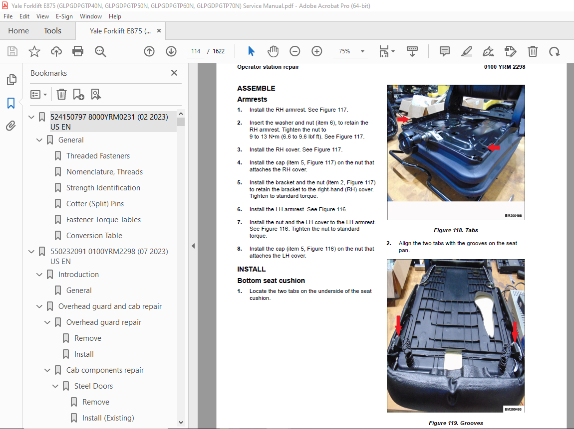
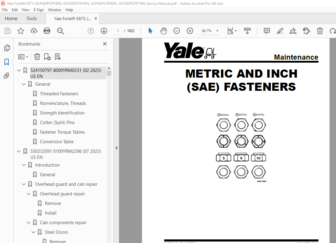
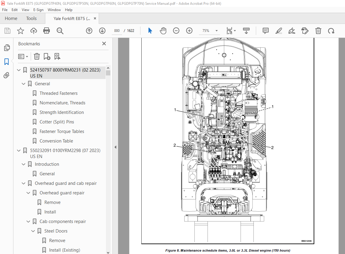
TABLE OF CONTENTS:
Yale Forklift E875 (GLPGDPGTP40N, GLPGDPGTP50N, GLPGDPGTP60N, GLPGDPGTP70N) Service Manual – PDF DOWNLOAD
524150797 8000YRM0231 (02 2023) US EN 1
General 7
Threaded Fasteners 7
Nomenclature, Threads 7
Strength Identification 8
Cotter (Split) Pins 9
Fastener Torque Tables 14
Conversion Table 16
550232091 0100YRM2298 (07 2023) US EN 23
Introduction 31
General 31
Overhead guard and cab repair 32
Overhead guard repair 32
Remove 32
Install 36
Cab components repair 37
Steel Doors 37
Remove 38
Install (Existing) 39
Install (New) 39
PVC Doors 41
Remove 42
Install 45
Screens 46
Front Screen and Wiper 46
Remove 46
Install 49
Top Screen and Wiper 51
Top Screen Remove 52
Top Screen Install 53
Top Wiper Remove 54
Top Wiper Install 56
Rear Screen and Wiper 57
Remove 58
Install 61
Washer Fluid Tank and Supply Lines 62
Remove (Washer Fluid Tank) 63
Install (Washer Fluid Tank) 64
Remove (Supply Lines) 64
Install (Supply Lines) 64
Operator Fan 65
Remove 65
Install 65
Front Grab Handle 65
Remove 65
Install 66
Rear Drive Handle with Horn Button 66
Remove 66
Install 66
12 Volt Power Supply with 2 USB Charging Ports 67
Remove (12 Volt Power Supply) 67
Install (12 Volt Power Supply) 67
Remove (USB Charging Ports) 67
Install (USB Charging Ports) 68
Dome Light 68
Remove 68
Install 68
Noise abatement (sound liners) 69
Hood liners 69
Remove 69
Install 69
Overhead guard liners 69
Remove 69
Install 69
Dash panel liners 70
Remove 70
Install 70
Heater and air conditioner repair 71
Heater repair 71
Heater 72
Remove 72
Install 73
Air conditioner repair 73
Air Conditioning 73
Safety Precautions 74
General Statements for Repairs 74
Residual Pressure 74
Refrigeration Circuit 74
Air Conditioner (A/C) Repair 74
Remove Condenser 76
Install Condenser 77
Remove A/C Compressor 78
Install A/C Compressor 78
Remove Tubes and Expansion Block Valve 79
Install Tubes and Expansion Block Valve 80
Operator station repair 81
Seat repair-Full Suspension 81
Remove 81
Disassemble 82
Armrests 82
Seats 82
Suspension (Seat pan) 84
Assemble 84
Suspension (Seat pan) 84
Seats 84
Armrests 85
Install 86
Seat repair-Non suspension seat 86
Remove 86
Disassemble 87
Operator Presence Sensor 87
Armrests 88
Seat rails 88
Assemble 88
Seat rails 88
Armrests 89
Operator Presence Sensor 89
Install 89
Seat repair-Air suspension 90
Remove 90
Disassemble 91
Armrests 91
Seat cushions 91
Backrest 93
Level adjustment handle 94
Bellows 95
Suspension (Seat pan) 97
Storage box 97
Backrest adjustment 98
Seat switch cable harness 99
Shock absorber 101
Seat plate 101
Static belt 102
Compressor 103
Air spring 104
Swinging structure 105
Assemble 106
Swinging structure 106
Air spring 106
Compressor 106
Seat plate 106
Static belt 106
Shock absorber 107
Seat switch cable harness 107
Backrest adjustment 107
Handles 108
Storage box 108
Bellows 108
Suspension (Seat pan) 108
Backrest 108
Seat cushions 108
Armrests 110
Install 110
Seat repair-value vinyl 111
Remove 111
Bottom seat cushion 112
Disassemble 113
Armrests 113
Assemble 114
Armrests 114
Install 114
Bottom seat cushion 114
Operator restraint system repair 116
Description 116
Seat belt-operational checkout 116
Emergency Locking Retractor (ELR) 116
Remove 116
Install 117
Pedals and linkage repair 117
Brake pedal 117
Remove 117
Install 120
Adjust 121
Throttle pedal (manual) 121
Remove 121
Install 123
Throttle pedal (electronic) 123
Remove 123
Install 124
Foot Directional Control pedal 125
Remove 125
Install 126
Dual pedal 126
Remove 126
Install 127
Park brake 127
Lift trucks with a with a Monotrol®Foot Directional Control pedal: 127
Adjust 127
Releasing the cable adjustment 128
Remove 128
Install 129
Accessories and options 131
Accessory options 131
Monitor holder 131
Tablet holder 131
Phone holder 131
Cup holder 132
Scanner holder 132
Tape dispenser 133
Stretch film roller 133
Accessory bar-fixed 133
Remove 133
Install 134
Accessory bar-swing out (rectangle OHG) 134
Remove 134
Install 135
Accessory bar-swing out (figure 8 OHG) 135
Remove 135
Install 135
Operator fan 136
Remove 136
Install 136
Sun shade 137
Remove 137
Install 137
550232092 0600YRM2299 (05 2023) US EN 139
Introduction 149
General 149
Engine identification 149
Major engine component identification 149
Location of labels 151
Diesel engine labels 151
LPG engine 152
Diesel engine repair 154
Diesel engine specifications 154
Cylinder head specifications 154
Camshaft and timing gear train specifications 156
Crankshaft and piston specifications 157
Cylinder block specifications 159
Special torque chart 160
Diesel cylinder head repair 162
Disassembly of Cylinder Head 162
Remove 168
Glow plugs 168
Valve cover 168
Rocker arm assembly 168
Cylinder head 169
Intake and exhaust valves 170
Valve guides 171
Clean and Inspect 171
Cylinder head components 172
Push rods 172
Push rod bend 172
Rocker arm assembly 172
Rocker arm shaft hole diameter 172
Valve guides 173
Cylinder head 173
Cylinder head distortion 173
Intake and exhaust valves 173
Valve stem diameter 173
Valve stem straightness 173
Valve recession 174
Valve face and valve seat 174
Valve springs 175
Assemble and Install 175
Valve Guides 175
Valves and valve springs 176
Cylinder head 177
Rocker arm assembly 177
Glow plugs 178
Valve cover 178
Engine assembly 178
Diesel timing gear case repair 179
Timing gear case cover 179
Remove 179
Inspect 180
Install 181
Timing gear case 181
Checks 181
Check timing gear backlash 181
Measuring idler gear-to-crankshaft gear backlash 181
Measuring idler gear-to-camshaft gear backlash 182
Remove 182
Install 184
Diesel camshaft and cylinder block repair 187
Remove engine components 188
Disassemble 188
Pistons and connecting rods 188
Remove 190
Crankshaft 190
Inspect 193
Crankshaft oil seals 193
Cylinder Block 194
Honing and Boring 196
Pistons 197
Connecting Rod 199
Tappets 199
Crankshaft 200
Camshaft 201
Camshaft bushing and bores 202
Idler gear and shaft 202
Assemble 203
Camshaft 203
Crankshaft 203
Pistons and Connecting Rods 205
Install 207
Diesel lubrication system repair 208
Check engine lubricating oil pressure 209
Remove 209
Oil pump components 209
Clean and inspect 211
Outer rotor outside clearance 211
Outer rotor to inner rotor tip clearance 211
Outer rotor side clearance 212
Rotor shaft clearance 212
Install 212
Oil pump service information 213
Diesel fuel system repair 214
Fuel system components 214
Remove 214
Injector 214
Common rail 216
Supply pump 217
Install 218
Supply pump 218
Common rail 218
Injector 219
Diesel flywheel repair 220
Remove 220
Install 220
Diesel electrical system repair 221
Starter 221
Remove 221
Disassemble 222
Install 222
Alternator 224
Remove 224
Install 224
Engine Control Unit 225
Remove 225
Install 225
Diesel exhaust and after treatment repair 226
Diesel Particulate Filter (DPF) System 226
Remove 226
DPF assembly 226
Soot filter 228
Inspect 229
Install 230
Soot filter 230
DPF assembly 231
Exhaust Gas Recirculation (EGR) system 232
EGR system configuration 232
Disassemble 232
EGR cooler 232
EGR valve and lead valve 233
Clean 234
EGR cooler 234
EGR pipe and other connecting elbows 234
EGR lead valve 234
Install 235
EGR valve and lead valve 235
EGR Cooler 235
Intake throttle 236
Precautions for handling the intake throttle 236
Exhaust throttle 236
Diesel engine checks, adjustments, and calibrations 237
Valve Clearance Adjustments 237
Alternator checks 238
Test stater coil continuity 238
Test stater coil short to ground 238
Test alternator regulated output 238
Exhaust and aftertreatment 239
EGR valve (check, clean, and test) 239
EGR active control 239
Precautions for cleaning 240
Cleaning the EGR valve 240
Exit the EGR active control 240
Intake throttle 240
Special tools for diesel engines 241
LPG engine repair 245
LPG engine specifications 245
Cylinder head specifications 245
Camshaft and timing gear train specifications 247
Crankshaft and piston specifications 248
Cylinder block specifications 250
Fuel specifications 250
Oil pump service information 251
Special torque chart 253
LPG cylinder head repair 255
Disassemble cylinder head 256
Remove 260
Valve cover 260
Rocker arm 260
Dissassemble rocker arm 260
Cylinder head 261
Intake and exhaust valves 262
Valve guides 262
Clean and Inspect 263
Cylinder head components 263
Push rods 263
Push rod bend 264
Rocker arm assembly 264
Rocker arm shaft hole diameter 264
Valve guides 264
Cylinder head 265
Cylinder head distortion 265
Intake and exhuast valves 265
Valve stem diameter 265
Valve stem straightness 265
Valve recession 265
Valve face and valve seat 266
Valve springs 267
Assemble 267
Valve guides 267
Valves and valve springs 268
Cylinder head 269
Rocker arm assembly 270
Install 271
LPG timing gear case repair 273
Remove 273
Timing gear case cover 273
Timing gear case 274
Idler shaft gear 274
Camshaft and camshaft gear 274
Timing gear case 276
Inspect 276
Install 276
LPG camshaft and cylinder block repair 278
Remove the engine components 279
Disassemble 279
Pistons and connecting rods 279
Remove 281
Crankshaft 281
Inspect 284
Crankshaft oil seals 284
Cylinder block 285
Honing and Boring 285
Pistons 286
Connecting Rod 288
Tappets 288
Crankshaft 289
Camshaft 290
Camshaft bushing and bores 291
Idler gear and shaft 291
Assemble 292
Pistons and Connecting Rods 292
Install 294
Crankshaft 294
Pistons 295
Install the engine components 296
LPG lubrication system repair 297
Check engine lubricating oil pressure 297
Remove 298
Oil pan 298
Oil pump 299
Clean and inspect 299
Outer rotor outside clearance 299
Outer rotor to inner rotor tip clearance 299
Outer rotor side clearance 300
Rotor shaft clearance 300
Assemble 301
Install 301
Oil pump 301
Oil pan 301
Oil pump service information 301
LPG fuel system repair 302
Fuel system components 302
Remove 302
Install 304
LPG flywheel repair 304
Remove 304
Inspect 305
Install 305
LPG electrical system repair 306
Starter 306
Remove 306
Install 306
Alternator 307
Remove 307
Install 307
Engine Control Unit 308
Remove 308
Install 308
LPG exhaust and aftertreatment repair 309
Remove 309
Inspect 311
Install 312
LPG engine checks, adjustments, and calibrations 313
Timing gear checks 313
Check timing gear backlash 313
Measuring idler gear-to-crankshaft gear backlash 313
Measuring idler gear-to-camshaft gear backlash 313
Valve Clearance Adjustments 314
Special tools for LPG engines 316
Bi-fuel engine repair 320
Bi-fuel engine specs 320
Bi-fuel cylinder head repair 320
Bi-fuel timing gear case repair 320
Bi-fuel camshaft and cylinder block repair 320
Bi-fuel lubrication system repair 320
Bi-fuel fuel system repair 320
Bi-fuel flywheel repair 320
Bi-fuel electrical system repair 320
Bi-fuel exhaust and aftertreatment repair 320
Bi-fuel engine checks, adjustments, and calibrations 320
Special tools for bi-fuel engines 320
550232093 0700YRM2300 (05 2023) US EN 323
Introduction 329
General 329
Cooling system repair 330
Fan repair 330
Remove 330
Inspect 332
Install 332
Fan repair (with hydraulic fan drive) 333
Remove 333
Inspect 337
Install 338
Water pump repair 339
Remove 339
Disassemble 342
Install 342
Radiator repair 343
Remove 343
Install 347
Radiator repair (with hydraulic fan drive) 348
Remove 348
Install 351
Cooling system flushing 352
Cooling system checks, adjustments, and calibrations 355
Hose check 355
Flow restriction check 355
Check for water flow restrictions in the radiator 355
Exhaust leak check 355
Thermostat and cooling system sensors check 355
Inspect 355
Temperature switch 355
Water temperature sensor 356
Thermostat 357
Radiator cap 357
550232095 1900YRM2302 (09 2023) US EN 359
Introduction 369
General 369
Hydraulic system repair 370
Hydraulic pump repair 370
Remove 370
Disassemble 376
Variable Displacement Pump 376
Hydraulic Gear Pump 378
Clean 380
Inspect 380
Assemble 380
Variable Displacement Pump 380
Hydraulic Gear Pump 380
Install 380
Variable Displacement Pump Checks and Adjustments 381
Pump Margin Pressure 381
Hydraulic control valve repair 382
Manual Control Valve 382
Remove 382
Disassemble 385
Clean and Inspect 385
Assemble 386
Install 386
Inlet Valve Section 386
Disassemble 386
Clean 387
Inspect 387
Assemble 387
Fan Drive Control Valve Section 388
Disassemble 388
Clean 389
Inspect 389
Assemble 389
Lift Control Valve Section 389
Disassemble 389
Clean 390
Inspect 390
Assemble 391
Tilt/Auxiliary Control Valve Sections 391
Disassemble 391
Clean 393
Inspect 393
Assemble 394
Outlet Valve Section 394
Disassemble 394
Clean 394
Inspect 395
Assemble 395
Accumulator 395
Remove 395
Install 396
Electronic Control Valve 396
Remove 396
Disassemble 398
Clean and Inspect 399
Assemble 399
Install 399
Inlet Valve Section 399
Disassemble 399
Clean 400
Inspect 400
Assemble 401
Fan Drive Control Valve Section 401
Disassemble 401
Clean 402
Inspect 402
Assemble 403
Lift Control Valve Section 403
Disassemble 403
Clean 404
Inspect 404
Assemble 405
Tilt/Auxiliary Control Valve Sections 405
Disassemble 405
Clean 406
Inspect 406
Assemble 407
Outlet Valve Section 407
Disassemble 407
Clean 407
Inspect 408
Assemble 408
Pressure Relief Valve Check and Adjustment 408
Primary Relief Valve 408
Secondary Relief Valve 409
Hydraulic supply and return repair 410
Hydraulic Supply and Return Hoses 410
Remove 410
Install 413
Mast Hoses 414
Remove 414
Install 418
Hydraulic Tank 418
Inspect 418
Clean 419
Steam Method of Cleaning 419
Chemical Solution Method of Cleaning 419
Additional Preparations for Repair 420
Small Leaks, Repair 420
Large Leaks, Repair 420
Preparations for use After Repair 420
Hydraulic oil cooler 420
Hydraulic Oil Cooler 420
Remove 420
Disassemble 421
Assemble 423
Install 423
Hydraulic calibrations 423
E-Hydraulic controls options 424
Calibration procedures 425
Service password entry 425
Hydraulic valve calibration warmup 426
Lift valve threshold 426
Lower valve threshold 426
Tilt valve threshold (Forward) 427
Tilt valve threshold (Back) 427
Auxiliary 1 Direction A valve output threshold 428
Auxiliary 1 Direction B valve output threshold 428
Auxiliary 2 Direction A valve output threshold 429
Auxiliary 2 Direction B valve output threshold 429
Steer system hydraulics repair 431
Steering pump repair 431
Remove 431
Disassemble 433
Clean 435
Inspect 435
Assemble 435
Install 435
Brake system hydraulics repair 436
Dry brake hydraulics repair 436
Wet brake hydraulics repair 436
Remove 436
Install 438
Cylinder repair 440
Tilt cylinder repair 440
Remove 440
Disassemble 441
Clean 442
Inspect 442
Assemble 443
Install 444
Tilt Cylinders, Adjust 444
Tilt Cylinders With Tilt Limit Spacers 444
Tilt Cylinders Without Tilt Limit Spacers 445
Tilt Cylinder Leak Check 446
Lift cylinder repair 446
Two-Stage Limited-Free-Lift (LFL) 446
Remove 446
Disassemble 447
Clean 448
Inspect 449
Assemble 449
Install 449
Two-Stage Full-Free-Lift (FFL) 450
Remove 450
Disassemble 451
Left-Hand Cylinder 451
Right-Hand Cylinder 452
Clean 453
Inspect 453
Assemble 454
Left-Hand Cylinder 454
Right-Hand Cylinder 455
Install 455
System Air Bleed Procedure 455
Three-Stage Full-Free-Lift (FFL) 456
Remove 456
Disassemble 457
Clean 458
Inspect 458
Assemble 459
Install 460
Four-Stage Full-Free-Lift (FFL) 460
Remove 460
Disassemble 461
Left-Hand main lift cylinder 461
Right-Hand main lift cylinder 462
Clean 463
Inspect 463
Assemble 464
Install 465
Free-Lift cylinder 465
Remove 465
Disassemble 466
Clean 467
Inspect 467
Assemble 468
Install 469
Seal Kit Installation 469
External Installation (Seal and Backup Ring) 469
Internal Installation (Piston Rod Assembly) 470
Lift cylinder leak check 470
Integral sideshift cylinder repair 470
General 470
Remove 470
Clean 472
Inspect 472
Assemble 472
Install 473
Integral Side-Shift Cylinder Gland Leak Checks 473
Hydraulics cleanliness 474
Flushing hydraulics after repair 474
Hydraulic System Flushing Techniques 474
Double Oil and Filter Change 474
Mechanical Cleaning 474
Cleaning of Components 474
Fluid conditioning and system flushing 475
Operation of the Filter Caddy 475
Filter Caddy operation 475
Fluid Conditioning Procedure 476
Filter Caddy Start-Up 476
System Flushing Procedure 477
Component Cleaning Procedure 477
Reservoir Cleaning Procedure 477
Cylinder Cleaning Procedure 477
Hose and Tube Cleaning Procedure 478
Valve Cleaning Procedure 478
Front-End Attachment Cleaning Procedure 479
System Flushing Procedure 479
Filter Caddy Start-Up 480
System Start-Up and Flushing 480
Reservoir Fluid Cleaning Times 481
Dealing With Different Fluid Types 481
Cleaning Procedure After Switching Fluids (Cross Contamination Flushing) 481
Filter Caddy Maintenance 482
Servicing the Strainer 482
DC Motor 482
Hydraulic oil sampling 482
Hydraulic Oil Sampling Method 482
Objective 482
General Guidelines 482
Synopsis 483
Hydraulic Oil Analysis Report Guidelines 484
Sampling Conditions 485
Equipment 485
Sampling Procedure 485
Hydraulic Oil Sampling 485
Sample Labeling 486
Results Documentation 486
550232096 4000YRM2303 (06 2023) US EN 489
Introduction 497
General 497
Safety Procedures When Working Near Mast 497
Fork and carriage repair 499
Fork removal and replacement 499
Integral Sideshift Carriage 499
Remove 499
Install 500
Checks 500
Carriage repair, 2-stage limited free lift 502
Standard Carriage 502
Remove 502
Clean and Inspect 503
Install 504
Integral Sideshift Carriage 505
Remove 505
Disassemble 508
Clean and Inspect 508
Assemble 509
Install 509
Auxiliary extension tubes (standard carriage) 510
Remove 510
Install 510
Auxiliary extension tubes (ISS carriage) 510
Remove 510
Install 510
Carriage repair, 2-stage full free lift 511
Standard Carriage 511
Remove 511
Clean and Inspect 512
Install 512
Integral Sideshift Carriage 513
Remove 513
Disassemble 516
Clean and Inspect 516
Assemble 517
Install 517
Auxiliary extension tubes (standard carriage) 518
Remove 518
Install 518
Auxiliary Extension Tubes (ISS Carriage) 518
Remove 518
Install 518
Carriage repair, 3-stage full free lift 519
Standard Carriage 519
Remove 519
Clean and Inspect 520
Install 520
Integral Sideshift Carriage 521
Remove 521
Disassemble 523
Clean and Inspect 524
Assemble 525
Install 525
Auxiliary extension tubes (standard carriage) 526
Remove 526
Install 526
Auxiliary extension tubes (ISS carriage) 526
Remove 526
Install 526
Carriage repair, 4-Stage Full Free Lift 527
Standard Carriage 527
Remove 527
Clean and Inspect 528
Install 529
Integral Sideshift Carriage 529
Remove 529
Disassemble 532
Clean and Inspect 532
Assemble 532
Install 533
Auxiliary Extension Tubes (Standard Carriage) 534
Remove 534
Install 534
Auxiliary Extension Tubes (ISS Carriage) 534
Remove 534
Install 535
Fork positioner 535
Mast repair 536
2-stage limited free lift (LFL) mast repair 536
Repair mast with serial number G507/G562 536
Remove 536
Disassemble 539
Clean and Inspect 544
Assemble 546
Install 547
2-stage full free lift (FFL) mast repair 549
Repair mast with serial number F509/F564 549
Remove 549
Disassemble 552
Clean and Inspect 554
Assemble 557
Install 558
3-stage full free lift (FFL) mast repair 559
Repair mast with serial number G508/G563 559
Remove 559
Disassemble 562
Clean and Inspect 566
Assemble 568
Install 569
4-Stage full free lift (FFL) Mast Repair 571
Repair Mast With Serial Number E515/B954 571
Remove 571
Disassemble 574
Clean and Inspect 580
Assemble 583
Install 584
Header Hose Repair 587
Header Hoses, 2-stage limited free lift (LFL) 587
Remove 587
Installation 587
Adjustment 589
Header Hoses, 2-stage full free lift (FFL) 589
Remove 589
Installation 590
Adjustment 594
Header Hoses, 3-stage full free lift (FFL) 595
Remove 595
Installation 595
Adjustment 599
Header Hose, 4-Stage Full Free Lift (FFL) 600
Remove 600
Install 601
Header Hose Tension Measurement Instructions 610
Adjustment 612
Adjustment Procedures 613
Carriage Adjustments 613
Lift Chains Adjustment 613
Lift Chains 613
Lift Trucks Equipped with Forks 614
Lift Trucks Equipped with Hook-Type Carriage and Attachment Without Forks 614
Mast Adjustments 614
Mast 614
Load Roller, Adjust 614
Mast Side Kicking, Adjust 617
Bolzoni attachment installation 618
Paper roll clamp installation 618
Bale clamp installation 618
Rotator installation 618
550232097 2200YRM2304 (07 2023) US EN 621
Introduction 635
General 635
Electrical system repair 636
Wire harness repair 636
Molex MX150 Series Connectors 636
MX150 Locations 641
Molex MX150 Series Terminals 641
Inspecting Wiring Terminals and Connectors 641
Removing Terminated Wires from Plug Connector 642
Removing Terminated Wires from Receptacle Connector 643
Installing Terminated Wires into Plug or Receptacle Connector 644
Wire Terminals 644
Unused Cavity Circuit Plug 644
Stripping Wire for Molex MX150 Series Terminals 644
Poor Wire Stripping Examples 645
Crimping Molex MX150 Series Terminals 646
Sensors, relays, and other electrical components repair 647
Sensors, Relays, and Other Electrical Components Repair 647
Accelerator Pedal Position Sensor 647
Remove 647
Install 648
Engine and Fuel Sensors and Switches, Yanmar Diesel Engine 648
Air Filter Restriction Switch 648
Remove 648
Install 648
Oil Pressure Sensor 648
Remove 648
Install 648
Engine Speed Sensor 648
Remove 648
Install 649
Engine Coolant Temperature (ECT) Sensor 649
Remove 649
Install 649
Throttle Position Sensor (TPS) 651
Remove 651
Install 652
Fuel/Water Separator Sensor 652
Remove 652
Install 652
Glow Plug Relay 653
Remove 653
Install 655
Engine Block Heater (2 1L Engine) 655
Remove 655
Install 655
Engine Block Heater (2 2L Engine) 656
Remove 656
Install 656
Exhaust Gas Sensors 656
Heated O2 Sensor 656
Remove 656
Install 657
Exhaust EGT Sensor 658
Remove 658
Install 658
Dynamic Stability System (DSS) 658
Mast Height Sensor (Discrete) 658
Remove 658
Install 659
Mast Height Sensor (Continuous) 659
Remove 659
Install 660
Mast Tilt Sensor 660
Remove 660
Install 661
Speed Sensor 661
Steer Axle Position Sensor 661
Remove 661
Install 662
Fuel Quality Sensor (FQS) – LPG/Dual Fuel Engines 662
Remove 662
Install 663
Synchronous Steering Column Sensor 663
Remove 663
Install 664
Service Brake Pedal Position Sensor – Single Pedal 664
Remove 664
Install 664
Brake Fluid Level Sensor 665
Remove 665
Install 665
Parking Brake Position Sensor 666
Remove 666
Install 666
Service Brake (Hydraulic) Pressure Transducer 666
Remove 666
Install 667
Service Brake (E-Brake) Position Sensor 667
Remove 667
Install 667
Monotrol Sensor 667
Remove 667
Install 668
Low Coolant Level Sensor 668
Remove 668
Install 669
Fuel Level Sensor, Gas and Diesel Engines Only 669
Remove 669
Install 669
Operator Presence Sensor 670
Remove 670
Install 670
Transmission Sensors 670
Speed Sensor 670
Remove 670
Install 671
Pressure Sensor 671
Remove 671
Install 671
Temperature Sensor 671
Remove 671
Install 671
Impact Sensor 671
Remove 671
Install 672
Load Weight Sensor 672
Remove 672
Install 672
Ambient Light Sensor 672
Remove 672
Install 674
Proximity Sensor 674
Remove 674
Install 674
Object Detection Sensors (Side) 675
Remove 675
Install 675
Object Detection Sensor (Rear) 675
Remove 675
Install 676
LPG Tank Interlock 676
Remove 676
Install 676
Smart Antenna 677
Remove 677
Install 677
Power distribution module (PDM) repair 677
Power Distribution Module 677
Remove 677
Install 678
Replacing PDM components (fuses and relays) 679
Battery service 682
Battery Remove and Install 682
Remove 682
Install 683
Battery Disconnect Switch (Optional) 683
Remove 684
Install 684
Light repair 684
Light Repair 684
LED Mast Lights 684
Remove 684
Install 685
LED Strobe Light 685
Remove 685
Install 685
Fork Laser Level Line 686
Remove 686
Install 686
Red or Blue Front Spot Light 686
Remove 686
Install 687
Red or Blue Rear Spot Light 687
Remove 687
Install 687
Front Work Lights 687
Remove 688
Install 688
Rear Work Light 688
Remove 688
Install 688
Rear Work Light with Red Line 689
Pedestrian Awareness Lights (PAL), Perimeter 689
Remove (Right Side) 689
Install (Right Side) 689
Remove (Rear) 689
Install (Rear) 690
Front LED Work Light with Marker Light 690
Remove 690
Install 691
Tail Light with Stop, Brake, Reverse, Hazard, and Turn Lights 691
Remove 691
Install 692
Controller removal and replacement 692
Controller Remove and Replace 692
VSM 692
Remove 692
Install 693
O-Box (E-Hydraulic) Controller 693
Remove 693
Install 694
Hydro Static Transmission (HST) controller 694
Remove 694
Install 695
I-Box (Accessory 1) 695
Remove 695
Install 695
I-Box (Accessory 2) 696
Remove 696
Install 696
Telemetry Wireless Asset Management System 696
Level 1 – Wireless Monitoring (WIFI Group) 696
Remove Telemetry Module 697
Install Telemetry Module 699
Remove Antenna 699
Install Antenna 700
Level 2 – Wireless Access 700
Telemetry Module 701
Antenna 701
RF-ID Reader 701
Remove 702
Install 702
Level 3 – Wireless Verification 702
Telemetry Module 703
Antenna 703
RF-ID Reader 703
Display Panel (Checklist) 703
Software 705
Loading and updating VSM software and truck Configuration Data Files (CDF)s with HYG Field Prog software 705
Installing the Field Prog software 705
Minimum system requirements 705
Open the Field Prog Tool 706
Using the Field Prog tool 707
Error behavior 711
CAN-based operations 712
Display programming 712
Programming the Display via USB 713
Setup 714
Run the Field Prog tool 714
Language 714
Loading and updating display and application software 715
Loading and Updating Display and Application Software 715
Minimum System Requirements 715
Configure Communications Settings 717
Installing Axcess Software 719
Using the Axcess Software 720
Programming the VSM 721
Begin Programming 722
Programming the Display via USB 722
Setup 723
Run the Tool 723
Transfer 724
Programming other controllers 724
Transmission Valve Calibration 725
Language 726
User interface (display) 726
User interface display 726
Navigation Key 726
Startup sequence 727
Side View Operator Screens 731
Switched Inputs and Preset Heights 732
Home screen 734
Loggin in 736
Log In or Out 736
Main Menu 737
View the Fault List 737
Fault List 737
Fault Filter 738
View hardware and software versions 739
Calibrations 739
Alarms 740
Diagnostics 741
Settings 744
Hydraulics 744
H1 Lift/Lower 744
H2 Tilt 745
H3 Third Hyd Function 745
H4 Fourth Hyd Function 745
H5 Fifth Hyd Function 745
H8 Pump 745
Drive 745
D1 Engine 745
D8 Traction 745
Sensors/Presets 745
Impact 746
Mast presets 746
Telemetry 746
Operators 746
Password Enabled 746
Add New 746
Existing User 746
Maintenance 747
M 1 Reminder 747
M 2 Checklist 747
Truck Setup 747
T1 Display 747
T2 Lights 747
T3 Time Out 747
T4 Alarms 747
T5 Alarms 748
T6 Inputs 748
Powertrain Protection System with Engine Shutdown 748
Powertrain Empty Seat Engine Shutdown 748
Display Icons 749
Service Display Menu Structure 771
Calibrations 796
Transmission warm-up 796
Hydraulic valve calibration warm-up 796
Calibrations 796
DSS calibrations 796
Return To Set Tilt Calibration 796
Synchronous Steering Calibration 797
Lift valve calibration 799
Lift valve threshold calibration 799
Lower valve calibration 801
Lower valve threshold calibration 801
Tilt back valve calibration 802
Tilt back valve output threshold calibration 802
Tilt forward valve calibration 803
Tilt forward valve output threshold calibration 803
Auxiliary valve direction A calibration 804
Auxiliary 1 or 2 direction A valve output threshold calibration 804
Auxiliary valve direction B calibration 806
Auxiliary 1 or 2 direction B valve output threshold calibration 806
Transmission calibration (Basic) 807
Prepare 807
Calibrations procedures 807
Transmission calibration (Advanced) 808
Calibrations procedures 808
Operator controls repair 813
Steering column repair 813
Description 813
Steering column assembly, remove 814
Battery disconnect 814
Remove operator controls from steering column 814
Remove covers, tilt only steering column 814
Remove covers, tilt and telescope steering column 815
Remove steering pump 816
Remove steering column assembly from truck 816
Steering column, disassemble 816
Tilt only 816
Tilt and telescope 816
Steering column, assemble 818
Tilt only 818
Tilt and telescope 818
Steering column assembly, install 818
Install steering column assembly in truck 818
Install steering pump 818
Install covers, tilt only steering column 818
Install covers, tilt and telescope steering column 818
Install operator controls on steering column 819
Connect battery 819
Display repair 819
Display remove and install 819
Remove 819
Install 820
Pinout descriptions for the 2 8-inch display 820
Pinout descriptions for the 5-inch display 821
Pinout descriptions for the 7-inch display 823
Operator buttons and switches repair 825
Park brake rocker switch 825
Remove 825
Install 825
Dash panel control module 825
Remove 825
Install 826
Cab Panel Control Module 826
Remove 826
Install 827
Mini-Lever Module 827
Remove 828
Install 828
Armrest assembly 828
Remove 828
Install 831
Rear drive handle with horn button 831
Remove 831
Install 832
Steering wheel horn switch 832
Remove 832
Install 833
Direction control lever (steering column) 833
Remove 833
Install 834
Turn signal lever 834
Remove 834
Install 836
Wiper control lever 836
Remove 836
Install 837
Battery disconnect switch 837
Remove 837
Install 838
Truck start switch 838
Keyed switch 838
Remove 838
Install 839
Keyless switch with Knob 839
Push button switch 840
Remove 840
Install 840
Push button with remote key switch 841
Remove 841
Install 841
Dome light switch 841
Remove 841
Install 842
E-hydraulic controls repair 842
E-hydraulic controls – TEST 842
Mini-levers 842
Full stroke test 842
Function returns to neutral test 842
Push (override) button 842
General 843
Mini-levers, remove and install 843
Armrest assembly 844
Remove 844
Install 846
Horn button 846
Remove 846
Install 846
Direction control switch 846
Remove 846
Install 847
Push (override) button 847
Remove 847
Install 848
Joystick controls repair 848
Joystick controls – TEST 848
Joystick levers 848
Full stroke test 848
Function returns to neutral test 849
General 850
Armrest assembly 850
Remove 850
Install 852
Joystick control levers 852
Remove 852
Install 852
Horn button 853
Remove 853
Install 853
Direction Control Switch 853
Remove 853
Install 854
550232099 8000YRM2305 (09 2023) US EN 857
Introduction 865
General 865
Truck handling and transport 866
How to move a disabled lift truck 866
How to Tow Lift Truck 866
How to put a lift truck on blocks 867
How to Raise Drive Tires 867
How to Raise Steering Tires 867
How to clean a lift truck 868
Putting a lift truck into storage 869
How to Put Internal Combustion Engine (ICE) Lift Trucks in Storage 869
Short-Term Storage 869
Long-Term Storage 870
While the Lift Truck is in Storage 870
How to Put Batteries in Storage 870
Preparing a stored lift truck for use 871
Putting a Stored Lift Truck Back Into Service 871
Wheels and tires 871
Periodic maintenance (PM) schedule 872
Daily periodic maintenance (PM) task schedule 872
First 150 hours periodic maintenance (PM) schedule 878
Every 500 hour periodic maintenance (PM) schedule 882
Every 1000 hour periodic maintenance (PM) schedule 888
Every 2000 hour periodic maintenance (PM) schedule 893
Every 3000 hour periodic maintenance (PM) schedule 898
Every 4000 hour periodic maintenance (PM) schedule 901
Every 5000 hour periodic maintenance (PM) schedule 905
Every 6000 hour periodic maintenance (PM) schedule 909
Periodic maintenance (PM) procedures 911
Daily periodic maintenance (PM) task procedures 911
How to make checks with engine stopped 911
Tires and wheels 911
Safety labels 911
Mast, carriage, lift chains, header hoses, attachment 912
Visual Inspection of Mast, Mast Hardware, and Tilt Cylinder Hardware 912
Operator restraint system 913
Seat belt-operational checkout 913
Emergency Locking Retractor (ELR) 913
Seat adjustments 913
Non-Suspension Seat 913
Full-Suspension Seat 913
Air-Suspension Seat 913
Hood and seat latches 915
Engine compartment 915
Fuel, oil, and coolant leaks, check 915
Hydraulic hoses 915
Coolant hoses 915
Steering column gas cylinder 915
Transmission (Powershift) 916
Hydraulic system oil 916
Engine oil 916
Air filter 918
Forks 919
Inspect 919
Fuel Filter/Water Separator 921
How to make checks with engine running 921
Indicator lights, horn, fuses, and relays 922
Service brakes 923
Brake fluid level 923
Operation, check 923
Park brake, Dry Brake Axle 923
Park Brake, Wet Brake Axle 924
Engine oil pressure 924
Cooling system 925
Lift system, operate 926
Check lift height sensor 926
First 150 hours periodic maintenance (PM) procedures 926
Yanmar engine oil and oil filter, Yanmar 2 1L, 3 0L, 3 3L Diesel and Yanmar 2 2L LPG 926
Transmission oil level (Powershift) 929
Transmission oil filter (Powershift) 929
Dry brake axle differential and drive axle oil 930
Wet brake axle differential (center section) and wheel end oil 930
Drive shaft inspection 932
Tilt cylinder mounting hardware inspection 933
Every 500 hour periodic maintenance (PM) procedures 934
Hydraulic tank breather 934
Inspect 934
Battery 934
Yanmar LPG engine oil and oil filter 935
Yanmar diesel engine oil and oil filter 936
Clean debris from radiator core and oil cooler 938
Transmission oil level (Powershift) 939
Mast Lubrication 940
Mast pivot pins and bushings 941
Tilt Cylinder Adjustments 942
Header Hose Checks 943
Lift Chain Lubrication 944
Tilt Cylinder Lubrication 944
Master brake cylinder rod end pin lubrication 945
Manual control levers lubrication 945
Steer axle tie rod lubrication 945
Differential and drive axle oil 946
Park brake 947
Brake pedal linkage 947
Tilt cylinder mounting hardware inspection 947
Every 1000 hour periodic maintenance (PM) procedures 948
Yanmar 2 2L LPG engine oil and oil filter 948
Pedals 949
Manual hydraulic control levers 950
Levers and linkage 950
Hood 951
Hinges 951
Hood latch 951
Integral sideshift carriage, check bearings 952
Check bearings 952
Check lower mounting hooks 952
Lift Chain Lubrication 953
Measure chain wear 953
LPG vaporizer and fuel filter 955
LPG vaporizer 955
LPG fuel filter element replace 957
Remove 957
Install 957
Engine electrical system 958
Check connectors 958
Fuel filter/water separator 958
Intake and exhaust throttle valves, Yanmar 3 0L and 3 3L engines 958
Valve clearance adjustments, Yanmar 3 0L and 3 3L engines 958
Steer axle king pin lubrication 960
Dry brake axle differential and drive axle oil 960
Wet brake axle differential (center section) oil 961
Park brake inspection 962
LPG tank bracket latch lubrication 962
LPG tank bracket release 963
Drive shaft inspection 963
Every 2000 hour periodic maintenance (PM) procedures 964
Hydraulic Filter 964
Hydraulic tank breather 966
Inspect 966
Air cleaner 966
Transmission oil drain and fill (Powershift) 967
Transmission oil filter (Powershift) 967
Integral Sideshift Carriage 968
Remove bearings 968
Brake fluid change (master cylinder) 969
Service brakes (dry brake drive axle) 969
Check thickness 969
Dry brake axle differential and drive axle oil 970
Wet brake axle differential (center section) and wheel end oil 970
EGR cooler 971
EGR pipe and other connecting elbows 972
Dry brake drive axle wheel bearing 972
Steer axle wheel bearing 972
Every 3000 hour periodic maintenance (PM) procedures 972
Intake and exhaust throttle valves, Yanmar 2 1L Diesel and 2 2L LPG Engines 972
Valve Clearance Adjustments, Yanmar 2 1L Diesel and 2 2L LPG Engines 972
Every 4000 hour periodic maintenance (PM) procedures 974
Cooling system 974
Coolant drain and flush 974
Coolant fill 975
Hydraulic Oil, Replace 976
Spark plugs, Yanmar 2 2L LPG engine 976
Every 5000 hour periodic maintenance (PM) procedures 976
V-belt (drive belt) 976
Auto tensioner 977
Every 6000 hour periodic maintenance (PM) procedures 978
DPF, Yanmar 2 1L diesel engine 978
PCV valve 978
550232100 8000YRM2306 (09 2023) US EN 981
Introduction 987
General 987
Covers, floorplates, and counterweight 988
Covers repair 988
Hood 988
Remove 988
Install 989
Steering column covers 990
Remove 990
Install 991
Kick panels 991
Remove 991
Install 993
Floormats and floorplates 993
Remove 993
Install 994
Dash covers 994
Remove 994
Install 995
Heating, Ventilation and Air Conditioning (HVAC) unit covers 995
Remove 995
Install 997
Counterweight repair 997
Counterweight Repair 997
Remove 997
Install 1001
LPG tank bracket repair 1002
LPG Tank Bracket Repair 1002
Fixed Bracket 1002
Remove 1002
Install 1003
Swing-Out Bracket 1003
Remove 1003
Install 1004
Swing-Out and Drop-Down Bracket 1005
Remove 1005
Install 1005
Frame repair 1007
Frame module repair 1007
Fuel tank repair 1007
Inspect 1007
Clean 1007
Steam method of cleaning 1008
Chemical solution method of cleaning 1008
Additional preparations for repair 1009
Small leaks, repair 1009
Large leaks, repair 1009
Preparations for use after repair 1009
Hydraulic oil tank repair 1009
Inspect 1009
Clean 1010
Steam method of cleaning 1010
Chemical solution method of cleaning 1011
Additional preparations for repair 1011
Small leaks, repair 1011
Large leaks, repair 1011
Preparations for use after repair 1011
Frame checks and adjustments 1011
Paint and labels 1012
General painting concerns 1012
Label replacement 1012
Tires and wheels 1017
Wheel and tire overview 1017
Snap-on wheel removal and replacement 1017
Snap-On-Tire, Change 1017
Remove Snap-On-Tire, Solid Tire From Wheel 1018
Install Snap-On-Tire, Solid Tire on Wheel 1019
Pneumatic tire removal and replacement (with tube) 1020
Remove wheels from lift truck 1020
Remove tire from wheel 1020
Remove Tire From Two-Piece Wheel 1021
Remove Tire From Three and Four-Piece Wheels 1022
Install wheel in tire 1023
Install Three-Piece or Four-Piece Wheel in Tire 1023
Add air to pneumatic tires with tube 1025
Install the wheels 1026
Pneumatic tire removal and replacement (without tube) 1027
Remove wheels from lift truck 1027
Remove Tire From Wheel 1027
Install Tire on Wheel 1029
Add Air to Pneumatic Tubeless Tire 1031
Wheels, Install 1032
Solid pneumatic tire repair and replacement 1032
Solid Rubber Tires on Pneumatic Wheels, Change 1032
Remove Tire From Wheel 1032
Install Tire on Wheel 1033
Optional features 1036
Debris screen 1036
Remove 1036
Install 1036
String cutter 1036
Remove 1036
Install 1037
550232101 8000YRM2307 (06 2023) US EN 1039
Introduction 1045
General 1045
Electrical schematics and diagrams 1046
Electrical schematics 1046
Hydraulic schematics 1084
Hydraulic Schematics – Transmission 1084
Hydraulic schematics – manual hydraulics with Powershift transmission 1089
Hydraulic schematics – e-hydraulics with Powershift transmission 1091
Hydraulic schematics – manual hydraulics with Hydrostatic transmission 1093
Hydraulic schematics – e-hydraulics with Hydrostatic transmission 1093
550232102 8000YRM2308 (08 2023) US EN 1095
Introduction 1109
General 1109
Frame 1110
Frame modular design description 1110
Frame attaching hardware description 1111
Hydraulics 1113
Hydraulic supply and return description 1113
Hydraulic Supply and Return 1113
Hydraulic pump description 1116
Hydraulic Pump 1116
Control valve description 1119
Control Valve 1119
Manual Control Valve 1119
Electro-Hydraulic Control Valve 1120
Manual Valve Main Components 1122
Control Valve Schematic 1122
Valve Section Breakdowns 1123
Inlet/Steer Section – Neutral/Steering Idle 1123
Inlet Section – Steering 1124
Lift Section – Neutral 1124
Lift Section – Neutral 1124
Lift Section – Lower 1125
Lift Section – Lower 1125
Lift Section – Raise 1126
Lift Section – Raise 1126
Tilt Section – Neutral 1127
Tilt Section – Spool IN 1127
Tilt Section – Spool OUT 1128
AUX 1 Section – Neutral 1128
AUX 1 Section – Spool IN 1129
AUX 1 Section – Spool OUT 1129
AUX 2 Section – Neutral 1130
AUX 2 Section – Spool IN 1130
AUX 2 Section – Spool OUT 1131
Unloader in Neutral – FDP 1131
Unloader in Function – FDP 1132
Anti-Stall Functionality 1132
Steering control unit description 1133
Steering Control Unit (SCU) 1133
Operation 1134
Brake system description 1137
Brake System Description 1137
Dry Brakes 1137
Master Cylinder 1139
Brake Position Sensor 1140
Wet Brakes 1140
Park Brake 1142
MONOTROL® Directional Control 1143
Inch Brake/Service Brake Pedal 1143
Electrical system 1145
Controller description 1145
Controller Description 1145
VSM 1145
OBox (Output Box) 1150
IBox (Input Box) 1152
Display (User Interface) 1155
Smart Antenna 1160
Impact Sensor 1162
Dash and Cab Switch Bank (Control Module) 1163
Mini-Lever Module (MLM) 1164
Hydro Static Transmission (HST) Controller 1166
Main Power Distribution Module (PDM) 1167
Power distribution module (PDM) description 1169
Power Distribution Module (PDM) 1169
Fuse and Relay Descriptions 1172
PDM Pin Out 1173
PDM Electrical Schematic 1175
Sensors description 1177
Sensors 1177
Operator Compartment 1177
Operator Presence Sensor (OPS) 1177
Steering Wheel Sensor 1178
Ambient Light Sensor 1178
Proximity Sensor 1179
Object Detection Sensors (Side) 1181
Objection Detection Sensor (Rear) 1181
Brake Pressure Sensor 1182
Service Brake Pedal Position Sensor 1183
E-Brake Position Sensor 1183
Park Brake Position Sensor 1184
Brake Fluid Level Sensor 1185
Accelerator Pedal Position (APP) Sensor 1185
Load Weight Sensor 1186
Frame 1186
Impact Sensor 1187
Steer Axle Position Sensor 1187
Mast 1188
Mast Lift Height Sensor (Discrete) 1188
Mast Height Sensor (Continuous) 1189
Mast Tilt Sensor 1189
Transmission Sensors 1190
Transmission Output Shaft Sensor (TOSS) 1190
Pressure Sensor 1191
Temperature Sensor 1191
Fuel 1192
Fuel Water Separator Sensor 1192
Fuel Level Sensor (Gas and Diesel Engines) 1192
LPG Tank Bracket Sensor 1193
Fuel Quality Sensor (FQS) – LPG and Dual Fuel Engines 1194
Engine 1195
Air Filter Restriction Sensor 1197
Throttle Position Sensor (TPS) 1197
Oil Pressure Sensor 1197
Engine Coolant Temperature (ECT) Sensor 1197
Engine Speed Sensor 1198
Low Coolant Level Sensor 1198
Exhaust System 1199
Heated Oxygen Sensor 1199
Exhaust Gas Temperature (EGT) Sensor 1199
EGR Temperature Sensor 1199
EGR Pressure Sensor 1199
Controller area network (CAN) description 1200
Controller Area Network (CAN) 1200
Operation 1200
Standard CAN 1201
Identifier Fields 1201
Message Types 1202
Multiple CANs 1202
CAN1 (Vehicle Bus) 1202
CAN2 (DriveTrain Bus) 1203
CAN3 (Front End) 1203
CAN4 (Service) 1204
CAN Failure 1204
Display description 1204
Display Description 1204
2 8-Inch Display 1204
5- or 7-Inch Display 1205
Electrical Specifications 1206
Wake Up 1206
Wake Up Output 1206
Memory Support 1206
Display Viewing 1207
Ambient Light Sensor 1207
Video Inputs 1207
Controller CAN Communications 1207
5-Button Keypad 1207
Male Connector Polarities 1208
2 8-Inch Display 1208
5-Inch Display 1210
7-Inch Display 1212
Battery description 1214
Battery Overview 1214
Battery Types 1215
Conventional 1215
Maintenance-Free 1215
Battery Charging 1215
Fast Charging 1216
Slow Charging 1216
Battery Disconnect Switch (Optional) 1216
Battery Charge Dongle (Optional) 1217
Lights description 1218
Lights 1218
Pedestrian Awareness Lights 1218
Orange Strobe Light 1218
Red or Blue Spot Lights 1219
Red LED Pedestrian Awareness Perimeter Lights 1220
Work Lights 1221
Front or Rear or Both 1221
Mast Mounted 1222
Brake, Tail, Reverse, Turn Signals, Hazard 1223
Brake Lights (Red) 1224
Tail Lights (Red) 1224
Turn Signals (Amber) 1224
Hazard 1224
Reverse Lights (White) 1224
Fork Laser Level Light (Line) 1224
Interior Reading Light (Cab Only) 1225
Software description 1225
Software Description 1226
Configuration Data File (CDF) 1226
Display Application (Program) 1226
Vehicle System Manager (VSM) Application (Program) 1226
Service Tools 1226
PC Service Tool (PCST) 1226
System Requirements 1227
Main Screen 1227
Field Prog Programming Tool 1228
Yanmar Smart Assist Direct (SAD) Tool (Engine) 1230
System Requirements 1230
ECU Replacement or Update 1231
Telemetry system description 1232
General 1232
Telemetry Module 1236
Basic Operations 1237
ID Card / ID Reader 1237
Interlock Relay 1238
Buzzer 1238
Wakeup 1238
Checklist 1238
Dynamic Stability System (DSS) 1238
Components of the DSS 1239
Vehicle System Manager (VSM) 1239
Lift Height Sensor 1239
Hydraulic Load Sensor 1239
Tilt Angle Sensor 1240
Tilt Override Button 1240
Speed Sensor 1240
Steer Angle Sensor 1240
DSS Subsystems 1240
Lateral Stability System 1240
High-Lift Traction Control 1240
High-Lift Tilt Control 1240
Corner Control 1241
DSS indicators and events 1241
Visual indicators 1242
Audible indicator 1243
Telemetry 1243
Operator’s cab 1244
Overhead guard description 1244
Overhead Guard 1244
Cab components description 1246
Cab Components 1246
Doors 1246
Steel Doors 1247
PVC Doors 1247
Screens 1249
Front Screen 1249
Top (Roof) Screen 1249
Rear Screen 1249
Wipers 1250
Front Screen and Wiper 1250
Top Screen and Wiper 1251
Rear Screen and Wiper 1252
Washer Fluid Tank and Supply Lines 1253
Heating and Cooling 1254
HVAC Controls 1260
Front and Rear Work Lights 1261
Strobe Light 1261
Operator Fan 1261
Front Grab Handle 1261
Rear Drive Handle with Horn Button 1262
12 Volt Power Supply with 2 USB Charging Ports 1262
12 Volt Auxiliary Wire Harness 1263
Reading (Dome) Light 1264
Seat description 1264
Seat Description 1264
Non-Suspension 1265
Semi-Suspension 1265
Full Suspension 1266
Air Ride Full Suspension 1266
Serviceable Parts 1266
Seat Belts 1266
Operator Presence Sensor (OPS) 1266
Operator controls description 1268
Operator Controls Description 1269
LCD Display (User Interface) 1269
Radio Frequency IDentification (RFID) Card Reader 1269
Steering Wheel and Horn 1270
Manual Hydraulic Levers 1270
Mini-Lever Module (MLM) Hydraulic Levers 1271
Joystick Hydraulic Controls 1271
Wiper Lever 1272
Turn Signal Lever 1273
Direction (FNR) Lever 1274
Dash and Cab Control Modules 1274
Manual Park Brake and Release 1275
Park Brake Rocker Switch (Optional) 1276
Accelerator Pedal 1276
Foot Direction Control (FDC) 1276
Dual Pedal Direction Control 1277
Keyed Ignition Switch 1277
Keyless Ignition Switch 1278
Pushbutton Ignition Switch 1278
Operator Seat 1279
Dome Light and Rocker Switch 1279
Rear Drive Handle with Horn Button 1280
Driver’s Fan and Fire Extinguisher 1280
Drivetrain 1281
Diesel engine description 1281
General Engine Information 1281
Combustion Theory 1281
Engine Block 1282
Camshaft and Timing Set 1284
Cylinder Head 1285
Valve Train 1287
Manifolds 1287
Intake 1287
Exhaust 1287
Air Cleaner/Filter 1288
Diesel Fuel System 1288
Electronic Fuel Injection (EFI) 1289
Positive Crankcase Ventilation (PCV) 1289
Battery Construction 1290
Conventional Standard Battery 1290
Maintenance-Free Battery 1291
Battery Charging 1291
Battery Fast Charging 1291
Battery Slow Charging 1292
Starting System Principles of Operation 1292
Starting System Components – Ignition Switch 1292
Starting System Components – Starter Solenoid 1292
Starting System Components – Flywheel and Ring Gear 1293
Starting System Components – Starter and Motor Drive 1293
Charging System – General 1295
Charging System – Regulator 1295
Charging System – Theory 1295
Exhaust Aftertreatment 1296
Description and Operation 1296
Diesel Particulate Filter (DPF) – Yanmar 1296
Yanmar Diesel Engine 1298
Yanmar Diesel Fuel System 1299
Fuel Water Separator 1300
Supply Pump 1301
Common Rail 1301
Injector 1301
Crankshaft Rotation Sensor and Gear Speed Sensor 1301
ECU 1301
Engine Mechanical 1302
Engine Cooling 1303
Engine Oil 1305
Engine Main Electronic Control Components 1306
Engine Control Unit (ECU) 1307
Fuel Feed Pump 1307
Fuel Pump (Supply Pump) 1307
Common Rail 1308
Fuel Injector 1308
Exhaust Gas Recirculation (EGR) valve 1308
Diesel Particulate Filter (DPF) 1309
Intake Throttle 1309
Exhaust Throttle (Optional) 1309
Accelerator Pedal Position (APP) Sensor 1310
Engine Coolant Temperature Sensor 1310
Crankshaft Rotation Sensor 1310
Gear Speed Sensor 1310
New Air Temperature Sensor 1311
Exhaust Gas Recirculation (EGR) Temperature Sensor 1311
EGR (EGR) Pressure Sensor 1311
Intake Air Temperature Sensor 1312
Engine Coolant Thermostat 1312
DPF Inside/Inlet Temperature Sensors 1313
DPF Differential Pressure Sensor 1313
Fuel Rail Pressure Sensor 1314
Engine ECU Management Controls 1314
Cold Start Assist 1314
Droop Control 1314
Isochronous Control 1314
Low-Idle Speed Up 1315
Turbocharger Protection (at low temperature) 1315
High-Idle Speed Reduction at Low Temperature (optional) 1315
Auto Idle Speed Reduction (optional) 1315
DPF Regeneration Control 1315
Self-Regeneration 1315
Assisted Regeneration 1315
Reset Regeneration 1315
Manual (Stationary) Regeneration 1315
Diagnostic Tool Tests and Adjustments 1315
EGR Active Control 1315
Exhaust Gas Throttle Active Control 1315
Intake Air Throttle Active Control 1315
LPG engine description 1315
Engine coolant system 1315
Engine oil 1316
Fuel system 1317
Vaporizer 1320
Balancing line 1320
Fuel rail 1320
Injector 1320
Crankshaft speed sensor and cam speed sensor 1320
Gas temperature pressure sensor 1320
ECU 1320
Engine trouble caused by improper fuel 1320
Fuel properties and engine performance 1320
Bi-fuel engine description 1321
CNG engine description 1321
Powershift transmission description 1321
Powershift Transmission 1321
Mechanical Overview 1321
Engine 1321
Torque Converter 1321
Stator 1322
Turbine 1322
Transmission 1323
Single-Speed 1325
Clutch Packs 1326
Forward Operation 1328
Reverse Operation 1328
Transmission Hydraulic Schematic 1328
Transmission Oil Flow 1332
Control Valve Oil Flow 1332
Control Valve 1333
Torque Converter Regulator 1335
Electrical System Architecture 1335
Transmission Input Shaft Speed (TISS) 1337
Transmission Output Shaft Speed (TOSS) 1338
Transmission Oil Temperature Sensor 1339
Accelerator Pedal Position (APP) Sensor 1339
Electrical Control Schematic 1340
Transmission Operational Modes 1342
Powered Off Mode 1342
Neutral Interlock Mode 1342
Normal Mode 1342
Fault Mode 1342
Pack Braking Mode 1342
Inching Mode 1342
Transmission Output Gear Yoke and Driveshaft 1342
Transmission, Driveshaft, and Drive Axle 1343
Hydrostatic transmission description 1344
Wet brake axle description 1344
Dry brake axle description 1344
Dry Brake Axle 1344
Synchronous steer axle description 1349
Synchronous Steering 1349
Operation 1350
Components 1350
Steering Wheel Sensor 1350
Steer Axle Position Sensor 1350
Calibration 1351
Synchronous Steering Hydraulic Schematic 1351
Non-synchronous steer axle description 1352
Non-Synchronous Steer Axle 1352
Steer Axle Components 1353
Top Bushing Blocks 1354
Center Pivot Mount Bushings 1354
Steer Axle Mounting Brackets 1354
Steering Cylinder 1354
Tie Rods 1354
Spindle Assembly 1355
Wheel Hub 1355
Powertrain Protection System 1355
Cooling 1357
Fan description 1357
Fan (Radiator Cooling) 1357
Crankshaft Belt Drive Fan 1357
Hydraulic Belt Drive Fan 1357
Cooling system description 1358
Cooling System 1358
Radiator 1359
Radiator Cap 1360
Cooling Fan 1360
Thermostat 1360
Coolant Pump 1361
Coolant Recovery Reservoir 1361
Coolant 1362
Radiator description 1362
Radiator 1362
Radiator Cap 1363
Charge Air Cooler (CAC) 1363
Radiator Screen (Optional) 1363
Front end 1364
Fork description 1364
Fork Description 1364
Fork Inspections and Service 1365
Fork Classification 1365
Fork Terminology 1366
Fork Tip Options 1368
Fork Bevel Options 1369
Fork Taper Options 1369
Fork Identification 1370
Miscellaneous Forks 1370
Standard Carriage and Forks 1370
Carriage description 1371
Carriage Description 1371
Carriage Classification 1371
Standard Carriage 1372
Load Backrest (LBR) Extension 1373
Integral Sideshift (ISS) Carriage 1375
Integral Sideshift Carriage with Fork Positioner (ISSFP) 1376
Mast description 1377
Mast Overview 1377
2-stage limited free lift (LFL) mast description 1378
2-stage LFL mast description 1378
Basic Operation 1380
Two Stage Limited Free-Lift 1381
Mast Hydraulic Components 1386
Two Stage LFL Header Hose 1386
Main Lift Cylinders 1388
Mast Hose Manifold 1389
Velocity Fuse 1389
Hoses and Hose Assemblies 1389
Hose Fittings 1389
Mast Mechanical Components 1390
Lift Chain 1390
Chain Anchors 1390
Chain Sheaves 1391
Load Rollers 1391
Wear Strips 1392
Mast Mounting Bushings 1392
2-stage full free lift (FFL) mast description 1392
2-stage FFL mast description 1392
Basic Operation 1394
Two Stage Full Free-Lift 1395
Mast Hydraulic Components 1401
Two Stage FFL Header Hose 1401
Free-Lift and Main Lift Cylinders 1403
Mast Hose Manifold 1404
Velocity Fuse 1405
Hoses and Hose Assemblies 1405
Hose Fittings 1405
Mast Mechanical Components 1405
Lift Chain 1405
Chain Anchors 1406
Chain Sheaves 1407
Load Rollers 1407
Wear Strips 1408
Mast Mounting Bushings 1408
3-stage full free lift (FFL) mast description 1409
3-Stage FFL mast description 1409
Basic Operation 1411
Three Stage Full Free-Lift 1412
Mast Hydraulic Components 1420
Three Stage FFL Header Hose 1420
Free-Lift and Main Lift Cylinders 1422
Mast Hose Manifold 1423
Velocity Fuse 1424
Hoses and Hose Assemblies 1424
Hose Fittings 1424
Mast Mechanical Components 1424
Lift Chain 1424
Chain Anchors 1425
Chain Sheaves 1426
Load Rollers 1426
Wear Strips 1427
Mast Mounting Bushings 1427
4-stage full free lift (FFL) mast description 1428
Paper roll clamp description 1428
Bale clamp description 1428
Rotator description 1428
550232103 8000YRM2309 (06 2023) US EN 1431
Introduction 1437
General 1437
Truck vital measurements 1438
Weight specifications 1438
Lift truck lifting capacity 1438
Counterweight weights 1438
Speed specifications 1438
Engine speeds 1438
Mast lower speeds 1439
Carriage lifting speeds with metric rated load at governed RPM and 55°C oil temperature (+/- 5%) 1439
Front end equipment max drift speeds* 1439
Dimension specifications 1440
Tire sizes 1440
Mast tilt specifications 1441
Pressure specifications 1441
Hydraulic system pressure specifications 1441
Coolant system pressure specifications 1441
Steering system pressure specifications 1441
Tire pressure specifications 1442
Transmission oil specifications 1442
Engine operation specifications 1443
Engine operation specifications 1443
Fluid specifications and capacities 1444
Fuel specifications and capacities 1444
Fuel tank capacity 1444
Lubricant specifications and capacities 1445
Engine oil 1445
Hydraulic tank oil 1445
Transmission oil 1446
Brake fluid 1446
Dry brake axle 1446
Wet brake axle 1446
Coolant specifications and capacities 1447
Cooling capacity 1447
Torque specifications 1448
Frame torque specifications 1448
Energy, electrical, and controls systems torque specifications 1448
Front end torque specifications 1448
Carriage 1448
Mast 2 stage FFL 1449
Mast 3 Stage FFL 1449
Mast 2 stage LFL 1449
Hydraulic torque specifications 1449
Operator station torque specifications 1450
Rectangle overhead guard 1450
Figure 8 overhead guard 1450
Drivetrain torque specifications 1451
Engine – Yanmar 2 1L Diesel 1451
Engine – Yanmar 2 2L LPG 1452
Transmission 1453
Drive axle (Dry Brake) 1453
Drive axle (Wet Brake) 1454
Brakes 1454
Park brake 1454
Steering axle 1454
550232104 8000YRM2310 (06 2023) US EN 1457
Error code reference charts 1463
Vehicle system manager (VSM) error code reference chart 1463
Engine error code reference chart 1477
Transmission error code reference chart 1565
Drive axle error code reference chart 1576
Front end error code reference chart 1582
Operator station error code reference chart 1597
Power supply error code reference chart 1605
Calibration error code reference chart 1615
Steering error code reference chart 1617
Hydraulic fan drive error code reference chart 1619
More products