$40.95
Yale Forklift F807 (ERP030_035_040TH) Service Manual – PDF DOWNLOAD
Yale Forklift F807 (ERP030_035_040TH) Service Manual – PDF DOWNLOAD
FILE DETAILS:
Yale Forklift F807 (ERP030_035_040TH) Service Manual – PDF DOWNLOAD
Language : English
Pages : 1014
Downloadable : Yes
File Type : PDF
IMAGES PREVIEW OF THE MANUAL:
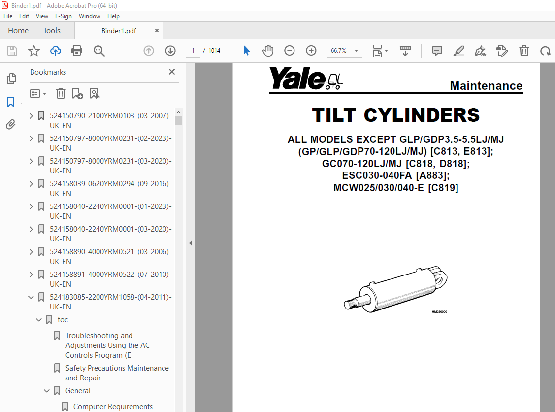
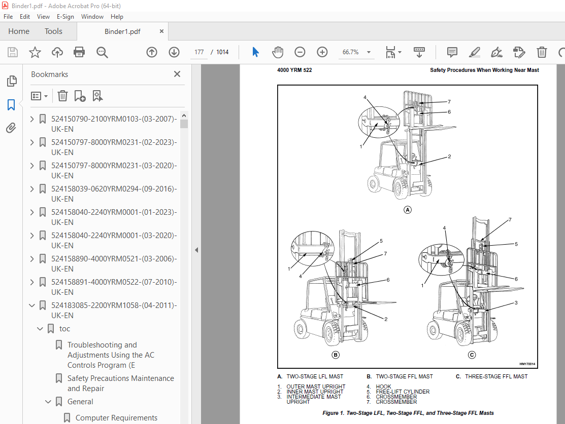
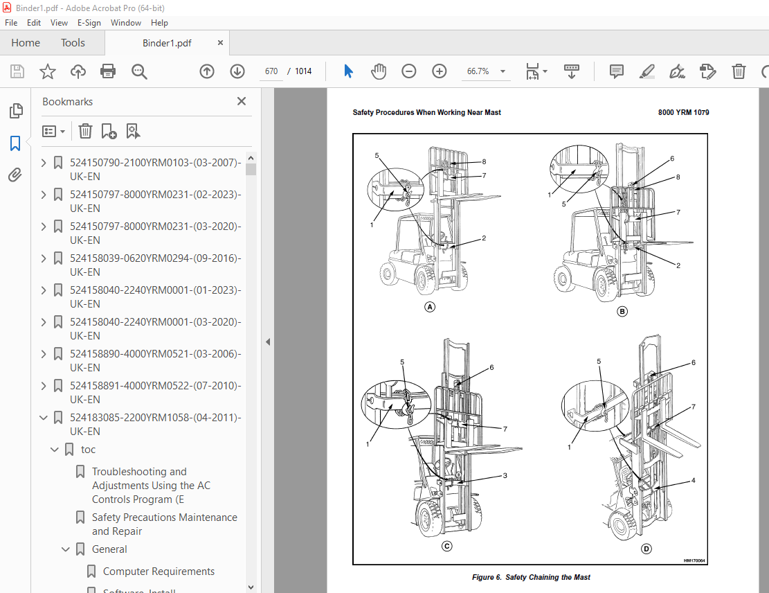
TABLE OF CONTENTS:
Yale Forklift F807 (ERP030_035_040TH) Service Manual – PDF DOWNLOAD
524150790-2100YRM0103-(03-2007)-UK-EN 1
toc 1
Tilt Cylinders 1
Safety Precautions Maintenance and Repair 2
General 5
Description 5
Tilt Cylinder Repair 5
Remove 5
Disassemble 5
Clean 5
Assemble 6
Tilt Cylinders With O-Ring or Single-Lip Seals 6
Tilt Cylinders 7
Install 8
Tilt Cylinder Leak Check 10
Tilt Cylinder Stroke and Mast Tilt Angle Adjustment 11
Torque Specifications 11
Piston Rod Nut 11
Retainer 11
Troubleshooting 12
tables 1
Table 1 Movement Rates (Maximum) for Tilt Cylinders 10
524150797-8000YRM0231-(02-2023)-UK-EN 17
General 23
Threaded Fasteners 23
Nomenclature, Threads 23
Strength Identification 24
Cotter (Split) Pins 25
Fastener Torque Tables 30
Conversion Table 32
524150797-8000YRM0231-(03-2020)-UK-EN 39
General 43
Threaded Fasteners 43
Nomenclature, Threads 43
Strength Identification 44
Cotter (Split) Pins 45
Fastener Torque Tables 50
Conversion Table 52
524158039-0620YRM0294-(09-2016)-UK-EN 59
General 63
Brush and Commutator Inspection 64
Hydraulic Pump Motor and Traction Motor 64
Steering Pump Motor 67
Normal Commutator Surface 67
Commutator Problems 67
Brush Replacement 72
Stoning the Commutator 75
Motors Repair 76
Disassemble 77
Traction Motor and Hydraulic Pump Motor 77
Steering Pump Motor 78
Assemble 82
Traction Motor and Hydraulic Pump Motor 82
Steering Pump Motor 84
Brush Alignment, Traction and Hydraulic Motors 86
Tests for Damaged Field and Armature 87
Test for an Open Circuit in One Armature Winding 87
Test for Short Circuit in One Armature Winding 87
Test for Short Circuit to Armature Shaft 88
Test for Open Circuit in Field Coil 88
Test for Short Circuit in Field Coil 89
Test for Short Circuit Between Field and Motor Case 89
Brush Holder Test 89
Troubleshooting 90
524158040-2240YRM0001-(01-2023)-UK-EN 95
General 101
Battery Type 101
Lead-Acid Batteries 101
Lithium-Ion Batteries 102
Specific Gravity 102
Chemical Reaction in a Cell 102
Electrical Terms 104
Battery Selection 105
Battery Voltage 106
Battery as a Counterweight 106
Battery Ratings 106
Kilowatt-Hours 106
Battery Maintenance 107
Safety Procedures 107
Maintenance Records 107
New Battery 107
Cleaning Battery 108
Adding Water to Battery 110
Hydrometer 110
Battery Temperature 111
Charging Battery 112
Types of Battery Charges 113
Methods of Charging 114
Troubleshooting Charger 115
Knowing When Battery Is Fully Charged 115
Where to Charge Batteries 115
Equipment Needed 115
Battery Connectors 116
Battery Care 116
Troubleshooting 118
524158040-2240YRM0001-(03-2020)-UK-EN 123
General 127
Battery Type 127
Lead-Acid Batteries 127
Lithium-Ion Batteries 128
Specific Gravity 128
Chemical Reaction in a Cell 128
Electrical Terms 130
Battery Selection 130
Battery Voltage 131
Battery as a Counterweight 132
Battery Ratings 132
Kilowatt-Hours 132
Battery Maintenance 132
Safety Procedures 132
Maintenance Records 133
New Battery 133
Cleaning Battery 133
Adding Water to Battery 135
Hydrometer 136
Battery Temperature 137
Charging Battery 138
Types of Battery Charges 138
Methods of Charging 140
Troubleshooting Charger 140
Knowing When Battery Is Fully Charged 141
Where to Charge Batteries 141
Equipment Needed 141
Battery Connectors 142
Battery Care 142
Troubleshooting 144
524158890-4000YRM0521-(03-2006)-UK-EN 149
toc 149
Mast 149
Safety Precautions Maintenance and Repair 150
General 153
Description and Operation 153
Carriages 153
Mast Mounts 155
Two-Stage Mast, Limited Free-Lift (LFL) 156
Description and Operation 156
Two-Stage Mast, Full Free-Lift (FFL) 158
Description and Operation 158
Three-Stage Mast, Full Free-Lift (FFL) 160
Description and Operation 160
Four-Stage Mast 162
Description and Operation 162
Cylinder Cushion During Lifting Sequence 166
Cylinder Cushion During Lowering Sequence 167
524158891-4000YRM0522-(07-2010)-UK-EN 171
toc 171
Mast 171
Safety Precautions Maintenance and Repair 172
General 175
Safety Procedures When Working Near Mast 176
Fork Repair 178
Remove 178
Install 178
Carriages Repair 180
Standard Carriage, Remove 180
Hang-On Sideshift Carriage, Remove 181
Standard Carriage and Hang-On Sideshift Carriage, Repair 182
Standard Carriage, Install 183
Hang-On Sideshift Carriage, Install 184
Integral Sideshift Carriage 184
Remove 184
Clean and Inspect 188
Repair 189
Install 190
Mast Repair 191
Remove 191
Two-Stage LFL and Two-Stage FFL Masts, Disassemble 193
Three-Stage FFL Mast 201
Disassemble 201
Mast and Chains, Clean and Inspect 204
Two-Stage LFL and Two-Stage FFL Mast, Assemble 205
Three-Stage FFL Mast, Assemble 206
Install 207
Lift Cylinders Repair 209
Main Lift Cylinders, Remove 209
Free-Lift Cylinder, Remove 209
Cylinders, Disassemble 210
Two-Stage Full Free-Lift Mast, Right-Hand Main Lift Cylinder 210
Two-Stage Full Free-Lift Mast, Left-Hand Main Lift Cylinder 212
Two-Stage Limited Free-Lift Mast and Three-Stage Full Free-Lift 212
Two-Stage Limited Free-Lift Mast and Three-Stage Full Free-Lift 213
Two-Stage Full Free-Lift Mast and Three-Stage Full Free-Lift Mas 214
Clean and Inspect 215
Cylinders, Assemble 215
Two-Stage Full Free-Lift Mast, Right-Hand Main Lift Cylinder 215
Two-Stage Full Free-Lift Mast, Left-Hand Main Lift Cylinder 216
Two-Stage Limited Free-Lift Mast and Three-Stage Full Free-Lift 217
Two-Stage Limited Free-Lift Mast and Three-Stage Full Free-Lift 217
Two-Stage Full Free-Lift Mast and Three-Stage Full Free-Lift Mas 218
Main Lift Cylinders, Install 219
Free-Lift Cylinder, Install 219
Header Hose Arrangements 220
Two-Stage LFL Mast, New Hose Install 220
Two-Stage LFL Mast, Adjust Hoses After Installation 225
Two-Stage FFL Mast, New Hose Install 225
Two-Stage FFL Mast, Adjust Hoses After Installation 233
Three-Stage FFL Mast, New Hose Install 233
Three-Stage FFL Mast, Adjust Hoses After Installation 244
Header Hose Arrangement 245
Two-Stage LFL Mast, New Hose Install 245
Two-Stage LFL Mast, Adjust Hoses After Installation 250
Two-Stage FFL Mast, New Hose Install 250
Two-Stage FFL Mast, Adjust Hoses After Installation 256
Three-Stage FFL Mast, New Hose Install 256
Three-Stage FFL Mast, Adjust Hoses After Install 265
Lift and Tilt System Leak Check 266
Lift Cylinders Leak Check 266
Tilt Cylinders Leak Check 266
Tilt Cylinders Adjustment 267
Lift Chains Adjustment 269
Mast Adjustment 271
Carriage Adjustment 273
Troubleshooting 274
tables 171
Table 1 Hook-Type Carriage Chain Adjustment 269
Table 2 Pin-Type Carriage Chain Adjustment 270
524183085-2200YRM1058-(04-2011)-UK-EN 277
toc 277
Troubleshooting and Adjustments Using the AC Controls Program (E 277
Safety Precautions Maintenance and Repair 278
General 281
Computer Requirements 281
Software, Install 281
Language Selection 281
Demo Mode 282
Connect PC to Lift Truck 286
Starting AC Controls Program 288
Lift Truck Control Setup 293
Change Lift Truck Serial Number or Hourmeter 293
Setting Factory Default Values or Changing Lift Truck Parameters 294
Create New Custom Lift Truck Configuration 300
Lift Truck Configuration Properties 303
Import New Lift Truck Configuration From Disk 306
Delete Custom Lift Truck Configuration or Password File 308
Dash Display 311
Custom Display Languages 311
Download Display Language 313
Clear Operator Log 313
Password Functions 316
Enable/Disable Password and Lift Truck Inspection Functions 316
Truck Inspection Checklist 316
Password 316
Password Properties 316
Create New Password File 321
Download Passwords 322
Upload Passwords 324
Reports Menu 326
Devices Report 326
Custom Report 326
Password Report 326
Operator Report 333
Current Settings Report 336
Status Code Report 340
Status Codes Log 343
Troubleshooting 345
Diagnostics 345
Help Menu 348
General 348
Contents 348
Technical Support 348
About Electric Truck AC Controls Program 348
524204497-0100YRM1073-(06-2004)-UK-EN 355
toc 355
Frame 355
Safety Precautions Maintenance and Repair 356
Introduction 359
General 359
Description of Operation 359
Discharging the Capacitors 360
Covers and Floor Plates 361
Overhead Guard Repair 363
Remove 363
Install 363
Hood and Seat Assembly 364
Remove 365
Install 365
Counterweight 366
Remove 366
Install 367
Safety Labels 368
Painting Instructions 371
524204498-1300YRM1074-(07-2009)-UK-EN 375
toc 375
Transaxle 375
Safety Precautions Maintenance and Repair 376
Introduction 379
General 379
Discharging the Capacitors 379
Description 381
Transmission 381
Traction Motor 381
Maintenance 382
Oil Level Check 382
Oil Change 382
Transaxle Assembly 383
Remove 383
Disassemble 384
Traction Motor and Covers 384
Brake Assembly and Gears 386
Planetary Gears and Drive Axle 387
Clean and Inspect 388
Assemble 389
Planetary Gears and Drive Axle 389
Brake Assembly and Gears 390
Traction Motor and Covers 391
Install 393
Troubleshooting 394
tables 375
Table 1 Special Tools 391
Table 2 Conventional Tools 391
524204499-1600YRM1075-(02-2008)-UK-EN 397
toc 397
Steering System 397
Safety Precautions Maintenance and Repair 398
Introduction 401
General 401
Discharging the Capacitors 401
Description of Operation 403
Steering Pressure Check 403
Operation Check 404
Steering Wheel and Column 405
Steering Column Covers 405
Remove 405
Install 405
Steering Column Components 406
Remove 406
Install 409
Steering Control Unit Assembly 410
Power Steering Pump and Motor 410
Description 410
Remove 410
Install 411
Disassemble 413
Assemble 414
Steering Actuator Components 414
Steer Tire and Wheel Assembly 414
Remove 414
Install 414
Wheel Hub Assembly 415
Remove 415
Install 415
Steering Axle Assembly 415
Remove 415
Clean 417
Install 417
Troubleshooting 418
524204500-1800YRM1076-(03-2007)-UK-EN 423
toc 423
Brake System 423
Safety Precautions Maintenance and Repair 424
Introduction 427
General 427
Discharging the Capacitors 427
Brake Pedal Assembly 428
Remove 428
Disassemble 428
Assemble 429
Install 430
Master Cylinder 430
Remove 430
Install 431
Adjustments 432
Bleed the Brake System 432
Adjust Linkage 432
Brake Lines 433
Parking Brake 433
Remove 433
Install 434
Troubleshooting 434
524204501-1900YRM1077-(09-2013)-UK-EN 439
toc 439
Hydraulic System 439
Safety Precautions Maintenance and Repair 440
Introduction 443
General 443
Discharging the Capacitors 444
Hydraulic System 445
Hydraulic Oil 445
Hydraulic Lines 445
Cleaning 445
Sound Level 445
Maintenance 446
Hydraulic Oil Filter, Change 446
Hydraulic Oil Strainer, Check 446
Hydraulic Oil, Change 447
Hydraulic Tank Assembly 448
Remove 448
Clean 449
Trisodium Phosphate Method 449
Install 449
Lift Pump and Motor 450
Remove 450
Disassemble 451
Assemble 451
Install 452
Lift Pump 453
Disassemble 453
Assemble 453
524204502-2000YRM1085-(10-2006)-UK-EN 457
toc 457
HUSCO™ Main Control Valve 457
Safety Precautions Maintenance and Repair 458
General 461
Description 461
Operation 462
Lift Section 464
Tilt Section 464
Tilt Backward 464
Tilt Forward 465
Relief Valve 466
Main Control Valve Repair 467
Remove 467
Disassemble 467
Clean and Inspect 469
Assemble 469
Install 471
Switch Plate Adjustment 473
Pressure Relief Valve Check and Adjustment 474
Primary Relief Valve 474
Secondary Relief Valve 474
Troubleshooting 475
524204503-2000YRM1086-(06-2004)-UK-EN 479
toc 479
Electro-Hydraulic Control Valve 479
Safety Precautions Maintenance and Repair 480
General 483
Description 483
Electro-Hydraulic Control System 483
Electro-Hydraulic Control Valve 484
Valve Driver Module 487
Manual Lowering Valve 487
Hydraulic Lever Console 487
Electro-Hydraulic Control Valve 487
Remove 487
Disassemble 488
Clean and Inspect 488
Assemble 489
Lift Valve Section 489
Tilt/Auxiliary Valve Sections 489
Valve Spool Coils 490
Fittings 490
Install 490
Check and Adjust 491
Tilt Counterbalance Valve 491
Main Relief Valve 491
Auxiliary Relief Valve 491
Valve Driver Module 491
Remove 491
Install 491
Hydraulic Lever Console 492
Remove 492
Disassemble 492
Covers 492
Hydraulic Control Lever 492
Main PC Board 492
Assemble 493
Main PC Board 493
Hydraulic Control Lever 493
Covers 493
Install 493
Troubleshooting 494
Troubleshooting Chart 494
tables 479
Table 1 Error Codes 494
524204504-2200YRM1087-(09-2013)-UK-EN 501
toc 501
AC Motor Controllers/Display Panel 501
Safety Precautions Maintenance and Repair 502
Description 505
General 505
Description 505
AC Motors 505
ZAPI™ AC Motor Controller 505
Principles of Operation 506
Controller Thermal Management 507
Controller Area Network (CANbus) 507
Discharging the Capacitors 507
AC Motor Controller Repair 509
General 509
Special Precautions 509
Thermal Sensors 510
Motor Controller, Replace 510
Controller Checks and Adjustments 510
Function Parameters 511
General 511
Function Parameter Descriptions 512
Parameters 512
Top Speed Forward 512
Top Speed Reverse 512
Acceleration 512
Regen Braking 513
Auto Deceleration 513
Extended Shift 513
Pump Acceleration 513
Tilt/Auxiliary Pump Acceleration 513
Low Lift Speed 513
Maximum Lift Speed 513
Maximum Lowering Speed 513
Tilt Speed 513
3rd Function 514
3rd Function Speed 514
4th Function 514
4th Function Speed 514
Battery Voltage 514
Lift Interrupt 514
BDI Adjustment (Early Models) 514
BDI Adjustment (Later Models) 514
BDI Decrement Time 515
Service Reminder 515
Custom 515
Restore Defaults 515
Calibration Parameters 516
Throttle Calibration 516
Steering Calibration 516
Display Panel 516
General 516
Premium Display Panel 516
Standard Display Panel 516
Display Functions and Features 516
Key-On Initialization 516
Standard Display 519
Premium Display 519
Lift Truck Inspection Function 520
Access to Service Functions 520
Service Functions 521
Performance Modes 522
Battery Discharge Indicator (BDI) 522
Hourmeter 523
Status Code List 523
Dash Display Service Menu Navigation 524
General 524
Moving Through Menu Selections 524
Editing and Adding Information 524
ETACC Test 525
Manual Hydraulics 525
Electro-Hydraulics 525
Troubleshooting 525
General 525
Status Codes 526
Controller Connector Pin Outs 616
Valve Driver Module (Electro-Hydraulic Valve Option) 617
Hydraulic Lever Console (Electro-Hydraulic Option Only) 618
Dash Display 618
System Logic Diagrams 619
tables 501
Table 1 Traction Parameters 511
Table 2 Transistor Lift With Manual Valve Parameters 511
Table 3 Transistor Lift With Electro-Hydraulic Valve Parameters 512
Table 4 List of Status Codes 526
Table 5 Connector A 616
Table 6 Connector C 616
Table 7 Connector D – Standard Model 617
Table 8 Connector D – Premium Model 617
Table 9 Connector B 617
Table 10 Connector C 617
524204505-2200YRM1078-(07-2005)-UK-EN 625
toc 625
Electrical System 625
Safety Precautions Maintenance and Repair 626
Introduction 629
General 629
Discharging the Capacitors 629
Emissions 631
Electromagnetic Interference 631
Motor Controllers 631
Controllers 631
Remove 631
Install 632
Hydraulics Contactor 633
Remove 633
Disassemble 633
Assemble 633
Install 633
Contactor Panel 634
Main Contactor 634
Remove 634
Disassemble 635
Assemble 635
Install 635
Contactor Coil 636
Contactor Tips 636
Fuses 636
Display Units 637
Features 637
Replace 638
Key Switch 638
Replace 638
Directional Controls 640
Directional Control Switches 640
Accelerator Switches and Pedal Assembly 641
Install 641
Calibrate 644
Foot Directional Control 644
Brakes 646
Brake Switch 646
Adjust or Replace 646
Master Cylinder Indicator 646
Parking Brake Disengage 647
Override Mode 647
Horn Components and Steering Encoder 648
Horn Components 648
Horn 648
Horn Button and Contacts 649
Steering Encoder 649
Hood and Seat Switches 650
Hood Position Switches 650
Seat Switch 650
Steer Angle Potentiometer 651
General 651
Operation 651
Example 651
Position Steer Tire for Straight Travel 652
Install 652
Set Potentiometer to Midpoint 652
Install to Steer Axle 652
Calibrate 653
Test 654
Wiring Harness 654
tables 625
Table 1 Potentiometer Specifications 654
524204506-8000YRM1079-(06-2009)-UK-EN 661
toc 661
Periodic Maintenance 661
Safety Precautions Maintenance and Repair 662
Introduction 665
General 665
Discharging the Capacitors 665
How to Move Disabled Lift Truck 667
How to Tow Lift Truck 667
How to Put Lift Truck on Blocks 668
How to Raise Drive Tires 668
How to Raise Steer Tires 668
Safety Procedures When Working Near Mast 669
Maintenance Schedule 671
Maintenance Procedures Every 8 Hours or Daily 675
Checks With the Key Switch OFF 675
Safety Labels and Decals 675
Frame 675
Wheels and Tires 675
Mast, Carriage, and Forks 675
Hydraulic Oil Level and Leaks 676
Operator and Battery Restraints 677
Battery Check 678
Checks With the Key Switch ON 678
Electrical Components 678
Directional Speed Control 678
Steering System 678
Hydraulic System 679
Brakes 679
Maintenance Procedures Every 500 Hours or 3 Months 679
Tire and Wheel Assemblies 679
Mast and Carriage 680
Hydraulics 681
Battery 681
Hydraulic Motor Brushes 681
Parking Brakes 681
Transaxle 683
Maintenance Procedures Every 1000 Hours or 6 Months 683
Lift Chains 683
Integral Sideshift Carriage 684
Check Upper and Lower Bearings 684
Hydraulic Breather Cap 684
Master Cylinder 685
Electrical Inspection 685
Contactors 685
Directional Speed Control 685
Transaxle, Oil Change 686
Maintenance Procedures Every 2000 Hours or Yearly 687
Steering 687
Hydraulic 687
Hydraulic Oil Filter, Change 687
Hydraulic Oil Strainer, Check 688
Hydraulic Oil, Change 688
Integral Sideshift Carriage 688
Replace Upper and Lower Bearings 688
General Repairs 689
Welding Repairs 689
Painting Instructions 689
Lift and Tilt System Leak Check 690
Lift System 690
Tilt System 690
Battery Maintenance 691
How to Charge Battery 691
How to Change Battery 692
Battery Size Specifications 692
tables 661
Table 1 Maintenance Schedule 672
524204507-8000YRM1080-(03-2009)-UK-EN 695
toc 695
Capacities and Specifications 695
Safety Precautions Maintenance and Repair 696
General 699
Lubrication Specifications 700
Hydraulic System 700
Steering System 701
Tire Sizes 702
Torque Specifications 703
Electrical 703
Steering System 703
Hydraulic System 703
Manual Hydraulic Valve 703
Transaxle 704
Transaxle Assembly 704
Travel Speeds 705
Battery 706
524204508-8000YRM1081-(04-2007)-UK-EN 713
toc 713
Diagrams 713
Safety Precautions Maintenance and Repair 714
524214915-0620YRM1115-(06-2006)-UK-EN 747
toc 747
AC Traction Motor Repair 747
Safety Precautions Maintenance and Repair 748
Introduction 751
General 751
Discharging the Capacitors 751
Description 753
Traction Motor 753
AC Motor Repair 754
Remove 754
Disassemble 754
Inspect 754
Assemble 756
Install 756
Troubleshooting 757
524223768-2100YRM1139-(02-2014)-UK-EN 761
524223776-4000YRM1148-(09-2015)-UK-EN 809
General 813
Safety Procedures When Working Near Mast 814
Fork Replacement 816
Remove, Lift Trucks Not Equipped With Fork Positioner Or Equipped With Fork Positioner Before August, 2012 816
Remove, Lift Trucks Manufactured After August, 2012 And Equipped With Fork Positioner 818
Install, Lift Trucks Not Equipped With Fork Positioner Or Equipped With Fork Positioner Before August, 2012 819
Install, Lift Trucks Manufactured After August, 2012 And Equipped With Fork Positioner 819
Checks, Lift Trucks Not Equipped With Fork Positioner Or Equipped With Fork Positioner Before August, 2012 820
Checks, Lift Trucks Manufactured After August, 2012 And Equipped With Fork Positioner 821
Carriages Repair 822
Standard Carriage 822
Remove 822
Repair 823
Install 823
Standard Carriage, Remove 824
Hang-On Sideshift Carriage, Remove 825
Standard Carriage and Hang-On Sideshift Carriage, Repair 826
Standard Carriage, Install 827
Hang-On Sideshift Carriage, Install 827
Integral Sideshift Carriage 828
Remove 828
Clean and Inspect 831
Repair 832
Install 832
Fork Positioner 833
Remove 833
Clean and Inspect 838
Disassemble and Assemble 838
Install 838
Fork Positioner Hydraulic Hose Adjustment 839
Disconnecting Attachment Hydraulic Quick Disconnect Hoses 841
Connecting Attachment Hydraulic Quick Disconnect Hoses 841
Mast Repair 842
Mast, Remove 842
Two-Stage LFL and Two-Stage FFL Masts 845
Disassemble 845
Clean and Inspect 855
Three-Stage FFL Mast 856
Disassemble 856
Clean and Inspect 864
Two-Stage LFL and Two-Stage FFL Mast 866
Assemble 866
Three-Stage FFL Mast 869
Assemble 869
Four-Stage FFL Mast – Manufactured Before July, 2009 871
Disassemble 871
Clean and Inspect 876
Assemble 878
Four-Stage FFL Mast – Manufactured After July, 2009 879
Disassemble 879
Clean and Inspect 886
Assemble 889
Mast, Install 890
Header Hose Arrangement 893
Two-Stage LFL 893
Two-Stage FFL 901
Three-Stage FFL 916
Standard 916
Optional Equipment Lift Truck GLP/GDP20-35VX (GP/GLP/GDP040-070VX) (B875) 933
Four-Stage FFL Mast – Manufactured Before July, 2009 941
Four-Stage FFL Mast – Manufactured After July, 2009 950
Adjustment 957
Lift Chains Adjustment 957
Carriage Adjustments 960
Mast Adjustments 960
Load Roller Adjustment 960
Mast Side Kicking Adjustment 963
580061048-4000YRM1176-(09-2013)-UK-EN 967
toc 967
Four-Stage (Quad) Mast 967
Safety Precautions Maintenance and Repair 968
General 971
Description 971
Carriages 971
Mast Mounts 972
Mast 973
Operation 974
Safety Procedures When Working Near Mast 979
Forks 981
Remove 981
Install 981
Checks 981
Carriage 983
Remove 983
Inspect 984
Install 985
Main Lift Cylinders Repair 986
Remove 986
Repair 986
Install 987
Free-Lift Cylinder Repair 988
Remove 988
Repair 988
Install 989
Lowering Control Valve 990
Valve Cartridge Service 990
Mast, Complete 991
Remove 991
Install 991
Mast Repair 993
Disassemble 993
Clean and Inspect 997
Assemble 999
Load rollers 1001
Reach Assembly 1001
Load Rollers and Wear Plugs 1001
Thrust Rollers 1001
Header Hose Arrangements 1002
Crosshead Assembly 1004
Lift Chains 1004
Inspect 1004
Clean and Lubricate 1004
Adjustments 1005
Mast Adjustments 1006
Skewing 1006
Shimming 1007
Carriage Adjustments 1007
Tilt Cylinders Adjustment 1008
Lift and Tilt System Leaks Check 1009
Lift Cylinders Leaks Check 1009
Tilt Cylinders Leaks Check 1009
Troubleshooting 1010
tables 967
Table 1 Fork Tip Alignment Specifications 982
More products