$41.95
Yale Forklift F807 (ERP1.6-1.8-2.0ATF) Service Manual – PDF DOWNLOAD
Yale Forklift F807 (ERP1.6-1.8-2.0ATF) Service Manual – PDF DOWNLOAD
FILE DETAILS:
Yale Forklift F807 (ERP1.6-1.8-2.0ATF) Service Manual – PDF DOWNLOAD
Language : English
Pages : 1148
Downloadable : Yes
File Type : PDF
IMAGES PREVIEW OF THE MANUAL:
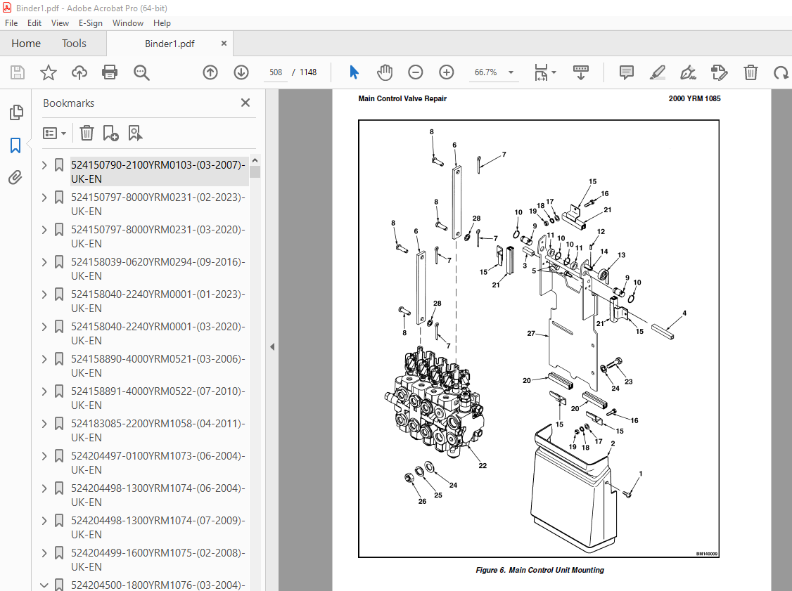
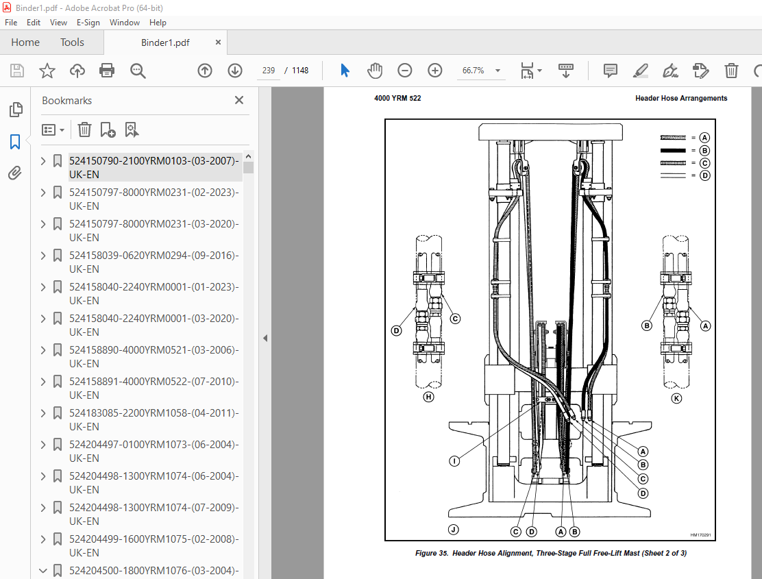
TABLE OF CONTENTS:
Yale Forklift F807 (ERP1.6-1.8-2.0ATF) Service Manual – PDF DOWNLOAD
524150790-2100YRM0103-(03-2007)-UK-EN 1
toc 1
Tilt Cylinders 1
Safety Precautions Maintenance and Repair 2
General 5
Description 5
Tilt Cylinder Repair 5
Remove 5
Disassemble 5
Clean 5
Assemble 6
Tilt Cylinders With O-Ring or Single-Lip Seals 6
Tilt Cylinders 7
Install 8
Tilt Cylinder Leak Check 10
Tilt Cylinder Stroke and Mast Tilt Angle Adjustment 11
Torque Specifications 11
Piston Rod Nut 11
Retainer 11
Troubleshooting 12
tables 1
Table 1 Movement Rates (Maximum) for Tilt Cylinders 10
524150797-8000YRM0231-(02-2023)-UK-EN 17
General 23
Threaded Fasteners 23
Nomenclature, Threads 23
Strength Identification 24
Cotter (Split) Pins 25
Fastener Torque Tables 30
Conversion Table 32
524150797-8000YRM0231-(03-2020)-UK-EN 39
General 43
Threaded Fasteners 43
Nomenclature, Threads 43
Strength Identification 44
Cotter (Split) Pins 45
Fastener Torque Tables 50
Conversion Table 52
524158039-0620YRM0294-(09-2016)-UK-EN 59
General 63
Brush and Commutator Inspection 64
Hydraulic Pump Motor and Traction Motor 64
Steering Pump Motor 67
Normal Commutator Surface 67
Commutator Problems 67
Brush Replacement 72
Stoning the Commutator 75
Motors Repair 76
Disassemble 77
Traction Motor and Hydraulic Pump Motor 77
Steering Pump Motor 78
Assemble 82
Traction Motor and Hydraulic Pump Motor 82
Steering Pump Motor 84
Brush Alignment, Traction and Hydraulic Motors 86
Tests for Damaged Field and Armature 87
Test for an Open Circuit in One Armature Winding 87
Test for Short Circuit in One Armature Winding 87
Test for Short Circuit to Armature Shaft 88
Test for Open Circuit in Field Coil 88
Test for Short Circuit in Field Coil 89
Test for Short Circuit Between Field and Motor Case 89
Brush Holder Test 89
Troubleshooting 90
524158040-2240YRM0001-(01-2023)-UK-EN 95
General 101
Battery Type 101
Lead-Acid Batteries 101
Lithium-Ion Batteries 102
Specific Gravity 102
Chemical Reaction in a Cell 102
Electrical Terms 104
Battery Selection 105
Battery Voltage 106
Battery as a Counterweight 106
Battery Ratings 106
Kilowatt-Hours 106
Battery Maintenance 107
Safety Procedures 107
Maintenance Records 107
New Battery 107
Cleaning Battery 108
Adding Water to Battery 110
Hydrometer 110
Battery Temperature 111
Charging Battery 112
Types of Battery Charges 113
Methods of Charging 114
Troubleshooting Charger 115
Knowing When Battery Is Fully Charged 115
Where to Charge Batteries 115
Equipment Needed 115
Battery Connectors 116
Battery Care 116
Troubleshooting 118
524158040-2240YRM0001-(03-2020)-UK-EN 123
General 127
Battery Type 127
Lead-Acid Batteries 127
Lithium-Ion Batteries 128
Specific Gravity 128
Chemical Reaction in a Cell 128
Electrical Terms 130
Battery Selection 130
Battery Voltage 131
Battery as a Counterweight 132
Battery Ratings 132
Kilowatt-Hours 132
Battery Maintenance 132
Safety Procedures 132
Maintenance Records 133
New Battery 133
Cleaning Battery 133
Adding Water to Battery 135
Hydrometer 136
Battery Temperature 137
Charging Battery 138
Types of Battery Charges 138
Methods of Charging 140
Troubleshooting Charger 140
Knowing When Battery Is Fully Charged 141
Where to Charge Batteries 141
Equipment Needed 141
Battery Connectors 142
Battery Care 142
Troubleshooting 144
524158890-4000YRM0521-(03-2006)-UK-EN 149
toc 149
Mast 149
Safety Precautions Maintenance and Repair 150
General 153
Description and Operation 153
Carriages 153
Mast Mounts 155
Two-Stage Mast, Limited Free-Lift (LFL) 156
Description and Operation 156
Two-Stage Mast, Full Free-Lift (FFL) 158
Description and Operation 158
Three-Stage Mast, Full Free-Lift (FFL) 160
Description and Operation 160
Four-Stage Mast 162
Description and Operation 162
Cylinder Cushion During Lifting Sequence 166
Cylinder Cushion During Lowering Sequence 167
524158891-4000YRM0522-(07-2010)-UK-EN 171
toc 171
Mast 171
Safety Precautions Maintenance and Repair 172
General 175
Safety Procedures When Working Near Mast 176
Fork Repair 178
Remove 178
Install 178
Carriages Repair 180
Standard Carriage, Remove 180
Hang-On Sideshift Carriage, Remove 181
Standard Carriage and Hang-On Sideshift Carriage, Repair 182
Standard Carriage, Install 183
Hang-On Sideshift Carriage, Install 184
Integral Sideshift Carriage 184
Remove 184
Clean and Inspect 188
Repair 189
Install 190
Mast Repair 191
Remove 191
Two-Stage LFL and Two-Stage FFL Masts, Disassemble 193
Three-Stage FFL Mast 201
Disassemble 201
Mast and Chains, Clean and Inspect 204
Two-Stage LFL and Two-Stage FFL Mast, Assemble 205
Three-Stage FFL Mast, Assemble 206
Install 207
Lift Cylinders Repair 209
Main Lift Cylinders, Remove 209
Free-Lift Cylinder, Remove 209
Cylinders, Disassemble 210
Two-Stage Full Free-Lift Mast, Right-Hand Main Lift Cylinder 210
Two-Stage Full Free-Lift Mast, Left-Hand Main Lift Cylinder 212
Two-Stage Limited Free-Lift Mast and Three-Stage Full Free-Lift 212
Two-Stage Limited Free-Lift Mast and Three-Stage Full Free-Lift 213
Two-Stage Full Free-Lift Mast and Three-Stage Full Free-Lift Mas 214
Clean and Inspect 215
Cylinders, Assemble 215
Two-Stage Full Free-Lift Mast, Right-Hand Main Lift Cylinder 215
Two-Stage Full Free-Lift Mast, Left-Hand Main Lift Cylinder 216
Two-Stage Limited Free-Lift Mast and Three-Stage Full Free-Lift 217
Two-Stage Limited Free-Lift Mast and Three-Stage Full Free-Lift 217
Two-Stage Full Free-Lift Mast and Three-Stage Full Free-Lift Mas 218
Main Lift Cylinders, Install 219
Free-Lift Cylinder, Install 219
Header Hose Arrangements 220
Two-Stage LFL Mast, New Hose Install 220
Two-Stage LFL Mast, Adjust Hoses After Installation 225
Two-Stage FFL Mast, New Hose Install 225
Two-Stage FFL Mast, Adjust Hoses After Installation 233
Three-Stage FFL Mast, New Hose Install 233
Three-Stage FFL Mast, Adjust Hoses After Installation 244
Header Hose Arrangement 245
Two-Stage LFL Mast, New Hose Install 245
Two-Stage LFL Mast, Adjust Hoses After Installation 250
Two-Stage FFL Mast, New Hose Install 250
Two-Stage FFL Mast, Adjust Hoses After Installation 256
Three-Stage FFL Mast, New Hose Install 256
Three-Stage FFL Mast, Adjust Hoses After Install 265
Lift and Tilt System Leak Check 266
Lift Cylinders Leak Check 266
Tilt Cylinders Leak Check 266
Tilt Cylinders Adjustment 267
Lift Chains Adjustment 269
Mast Adjustment 271
Carriage Adjustment 273
Troubleshooting 274
tables 171
Table 1 Hook-Type Carriage Chain Adjustment 269
Table 2 Pin-Type Carriage Chain Adjustment 270
524183085-2200YRM1058-(04-2011)-UK-EN 277
toc 277
Troubleshooting and Adjustments Using the AC Controls Program (E 277
Safety Precautions Maintenance and Repair 278
General 281
Computer Requirements 281
Software, Install 281
Language Selection 281
Demo Mode 282
Connect PC to Lift Truck 286
Starting AC Controls Program 288
Lift Truck Control Setup 293
Change Lift Truck Serial Number or Hourmeter 293
Setting Factory Default Values or Changing Lift Truck Parameters 294
Create New Custom Lift Truck Configuration 300
Lift Truck Configuration Properties 303
Import New Lift Truck Configuration From Disk 306
Delete Custom Lift Truck Configuration or Password File 308
Dash Display 311
Custom Display Languages 311
Download Display Language 313
Clear Operator Log 313
Password Functions 316
Enable/Disable Password and Lift Truck Inspection Functions 316
Truck Inspection Checklist 316
Password 316
Password Properties 316
Create New Password File 321
Download Passwords 322
Upload Passwords 324
Reports Menu 326
Devices Report 326
Custom Report 326
Password Report 326
Operator Report 333
Current Settings Report 336
Status Code Report 340
Status Codes Log 343
Troubleshooting 345
Diagnostics 345
Help Menu 348
General 348
Contents 348
Technical Support 348
About Electric Truck AC Controls Program 348
524204497-0100YRM1073-(06-2004)-UK-EN 355
toc 355
Frame 355
Safety Precautions Maintenance and Repair 356
Introduction 359
General 359
Description of Operation 359
Discharging the Capacitors 360
Covers and Floor Plates 361
Overhead Guard Repair 363
Remove 363
Install 363
Hood and Seat Assembly 364
Remove 365
Install 365
Counterweight 366
Remove 366
Install 367
Safety Labels 368
Painting Instructions 371
524204498-1300YRM1074-(06-2004)-UK-EN 375
toc 375
Transaxle 375
Safety Precautions Maintenance and Repair 376
Introduction 379
General 379
Discharging the Capacitors 379
Description 381
Transmission 381
Traction Motor 381
Maintenance 382
Oil Level Check 382
Oil Change 382
Transaxle Assembly 383
Remove 383
Disassemble 384
Traction Motor and Covers 384
Brake Assembly and Gears 385
Planetary Gears and Drive Axle 387
Clean and Inspect 388
Assemble 389
Planetary Gears and Drive Axle 389
Brake Assembly and Gears 390
Traction Motor and Covers 391
Install 393
Troubleshooting 394
tables 375
Table 1 Special Tools 391
Table 2 Conventional Tools 391
524204498-1300YRM1074-(07-2009)-UK-EN 397
toc 397
Transaxle 397
Safety Precautions Maintenance and Repair 398
Introduction 401
General 401
Discharging the Capacitors 401
Description 403
Transmission 403
Traction Motor 403
Maintenance 404
Oil Level Check 404
Oil Change 404
Transaxle Assembly 405
Remove 405
Disassemble 406
Traction Motor and Covers 406
Brake Assembly and Gears 408
Planetary Gears and Drive Axle 409
Clean and Inspect 410
Assemble 411
Planetary Gears and Drive Axle 411
Brake Assembly and Gears 412
Traction Motor and Covers 413
Install 415
Troubleshooting 416
tables 397
Table 1 Special Tools 413
Table 2 Conventional Tools 413
524204499-1600YRM1075-(02-2008)-UK-EN 419
toc 419
Steering System 419
Safety Precautions Maintenance and Repair 420
Introduction 423
General 423
Discharging the Capacitors 423
Description of Operation 425
Steering Pressure Check 425
Operation Check 426
Steering Wheel and Column 427
Steering Column Covers 427
Remove 427
Install 427
Steering Column Components 428
Remove 428
Install 431
Steering Control Unit Assembly 432
Power Steering Pump and Motor 432
Description 432
Remove 432
Install 433
Disassemble 435
Assemble 436
Steering Actuator Components 436
Steer Tire and Wheel Assembly 436
Remove 436
Install 436
Wheel Hub Assembly 437
Remove 437
Install 437
Steering Axle Assembly 437
Remove 437
Clean 439
Install 439
Troubleshooting 440
524204500-1800YRM1076-(03-2004)-UK-EN 445
toc 445
Brake System 445
Safety Precautions Maintenance and Repair 446
Introduction 449
General 449
Discharging the Capacitors 449
Brake Pedal Assembly 451
Remove 451
Disassemble 451
Assemble 451
Install 451
Master Cylinder 453
Remove 453
Install 454
Adjustments 454
Bleed the Brake System 454
Adjust Linkage 454
Brake Lines 455
Parking Brake 455
Remove 455
Disassemble 457
Assemble 457
Install 457
Troubleshooting 458
524204500-1800YRM1076-(03-2007)-UK-EN 463
toc 463
Brake System 463
Safety Precautions Maintenance and Repair 464
Introduction 467
General 467
Discharging the Capacitors 467
Brake Pedal Assembly 468
Remove 468
Disassemble 468
Assemble 469
Install 470
Master Cylinder 470
Remove 470
Install 471
Adjustments 472
Bleed the Brake System 472
Adjust Linkage 472
Brake Lines 473
Parking Brake 473
Remove 473
Install 474
Troubleshooting 474
524204501-1900YRM1077-(09-2013)-UK-EN 479
toc 479
Hydraulic System 479
Safety Precautions Maintenance and Repair 480
Introduction 483
General 483
Discharging the Capacitors 484
Hydraulic System 485
Hydraulic Oil 485
Hydraulic Lines 485
Cleaning 485
Sound Level 485
Maintenance 486
Hydraulic Oil Filter, Change 486
Hydraulic Oil Strainer, Check 486
Hydraulic Oil, Change 487
Hydraulic Tank Assembly 488
Remove 488
Clean 489
Trisodium Phosphate Method 489
Install 489
Lift Pump and Motor 490
Remove 490
Disassemble 491
Assemble 491
Install 492
Lift Pump 493
Disassemble 493
Assemble 493
524204502-2000YRM1085-(03-2004)-UK-EN 497
toc 497
HUSCO™ Main Control Valve 497
Safety Precautions Maintenance and Repair 498
General 501
Description 501
Operation 501
Lift Section 504
Tilt Section 504
Tilt Backward 504
Tilt Forward 504
Relief Valve 506
Main Control Valve Repair 507
Remove 507
Disassemble 509
Clean and Inspect 509
Assemble 509
Install 511
Pressure Relief Valve Check and Adjustment 514
Primary Relief Valve 514
Secondary Relief Valve 514
Troubleshooting 515
524204502-2000YRM1085-(10-2006)-UK-EN 519
toc 519
HUSCO™ Main Control Valve 519
Safety Precautions Maintenance and Repair 520
General 523
Description 523
Operation 524
Lift Section 526
Tilt Section 526
Tilt Backward 526
Tilt Forward 527
Relief Valve 528
Main Control Valve Repair 529
Remove 529
Disassemble 529
Clean and Inspect 531
Assemble 531
Install 533
Switch Plate Adjustment 535
Pressure Relief Valve Check and Adjustment 536
Primary Relief Valve 536
Secondary Relief Valve 536
Troubleshooting 537
524204503-2000YRM1086-(06-2004)-UK-EN 541
toc 541
Electro-Hydraulic Control Valve 541
Safety Precautions Maintenance and Repair 542
General 545
Description 545
Electro-Hydraulic Control System 545
Electro-Hydraulic Control Valve 546
Valve Driver Module 549
Manual Lowering Valve 549
Hydraulic Lever Console 549
Electro-Hydraulic Control Valve 549
Remove 549
Disassemble 550
Clean and Inspect 550
Assemble 551
Lift Valve Section 551
Tilt/Auxiliary Valve Sections 551
Valve Spool Coils 552
Fittings 552
Install 552
Check and Adjust 553
Tilt Counterbalance Valve 553
Main Relief Valve 553
Auxiliary Relief Valve 553
Valve Driver Module 553
Remove 553
Install 553
Hydraulic Lever Console 554
Remove 554
Disassemble 554
Covers 554
Hydraulic Control Lever 554
Main PC Board 554
Assemble 555
Main PC Board 555
Hydraulic Control Lever 555
Covers 555
Install 555
Troubleshooting 556
Troubleshooting Chart 556
tables 541
Table 1 Error Codes 556
524204504-2200YRM1087-(09-2013)-UK-EN 563
toc 563
AC Motor Controllers/Display Panel 563
Safety Precautions Maintenance and Repair 564
Description 567
General 567
Description 567
AC Motors 567
ZAPI™ AC Motor Controller 567
Principles of Operation 568
Controller Thermal Management 569
Controller Area Network (CANbus) 569
Discharging the Capacitors 569
AC Motor Controller Repair 571
General 571
Special Precautions 571
Thermal Sensors 572
Motor Controller, Replace 572
Controller Checks and Adjustments 572
Function Parameters 573
General 573
Function Parameter Descriptions 574
Parameters 574
Top Speed Forward 574
Top Speed Reverse 574
Acceleration 574
Regen Braking 575
Auto Deceleration 575
Extended Shift 575
Pump Acceleration 575
Tilt/Auxiliary Pump Acceleration 575
Low Lift Speed 575
Maximum Lift Speed 575
Maximum Lowering Speed 575
Tilt Speed 575
3rd Function 576
3rd Function Speed 576
4th Function 576
4th Function Speed 576
Battery Voltage 576
Lift Interrupt 576
BDI Adjustment (Early Models) 576
BDI Adjustment (Later Models) 576
BDI Decrement Time 577
Service Reminder 577
Custom 577
Restore Defaults 577
Calibration Parameters 578
Throttle Calibration 578
Steering Calibration 578
Display Panel 578
General 578
Premium Display Panel 578
Standard Display Panel 578
Display Functions and Features 578
Key-On Initialization 578
Standard Display 581
Premium Display 581
Lift Truck Inspection Function 582
Access to Service Functions 582
Service Functions 583
Performance Modes 584
Battery Discharge Indicator (BDI) 584
Hourmeter 585
Status Code List 585
Dash Display Service Menu Navigation 586
General 586
Moving Through Menu Selections 586
Editing and Adding Information 586
ETACC Test 587
Manual Hydraulics 587
Electro-Hydraulics 587
Troubleshooting 587
General 587
Status Codes 588
Controller Connector Pin Outs 678
Valve Driver Module (Electro-Hydraulic Valve Option) 679
Hydraulic Lever Console (Electro-Hydraulic Option Only) 680
Dash Display 680
System Logic Diagrams 681
tables 563
Table 1 Traction Parameters 573
Table 2 Transistor Lift With Manual Valve Parameters 573
Table 3 Transistor Lift With Electro-Hydraulic Valve Parameters 574
Table 4 List of Status Codes 588
Table 5 Connector A 678
Table 6 Connector C 678
Table 7 Connector D – Standard Model 679
Table 8 Connector D – Premium Model 679
Table 9 Connector B 679
Table 10 Connector C 679
524204505-2200YRM1078-(07-2005)-UK-EN 687
toc 687
Electrical System 687
Safety Precautions Maintenance and Repair 688
Introduction 691
General 691
Discharging the Capacitors 691
Emissions 693
Electromagnetic Interference 693
Motor Controllers 693
Controllers 693
Remove 693
Install 694
Hydraulics Contactor 695
Remove 695
Disassemble 695
Assemble 695
Install 695
Contactor Panel 696
Main Contactor 696
Remove 696
Disassemble 697
Assemble 697
Install 697
Contactor Coil 698
Contactor Tips 698
Fuses 698
Display Units 699
Features 699
Replace 700
Key Switch 700
Replace 700
Directional Controls 702
Directional Control Switches 702
Accelerator Switches and Pedal Assembly 703
Install 703
Calibrate 706
Foot Directional Control 706
Brakes 708
Brake Switch 708
Adjust or Replace 708
Master Cylinder Indicator 708
Parking Brake Disengage 709
Override Mode 709
Horn Components and Steering Encoder 710
Horn Components 710
Horn 710
Horn Button and Contacts 711
Steering Encoder 711
Hood and Seat Switches 712
Hood Position Switches 712
Seat Switch 712
Steer Angle Potentiometer 713
General 713
Operation 713
Example 713
Position Steer Tire for Straight Travel 714
Install 714
Set Potentiometer to Midpoint 714
Install to Steer Axle 714
Calibrate 715
Test 716
Wiring Harness 716
tables 687
Table 1 Potentiometer Specifications 716
524204506-8000YRM1079-(06-2009)-UK-EN 723
toc 723
Periodic Maintenance 723
Safety Precautions Maintenance and Repair 724
Introduction 727
General 727
Discharging the Capacitors 727
How to Move Disabled Lift Truck 729
How to Tow Lift Truck 729
How to Put Lift Truck on Blocks 730
How to Raise Drive Tires 730
How to Raise Steer Tires 730
Safety Procedures When Working Near Mast 731
Maintenance Schedule 733
Maintenance Procedures Every 8 Hours or Daily 737
Checks With the Key Switch OFF 737
Safety Labels and Decals 737
Frame 737
Wheels and Tires 737
Mast, Carriage, and Forks 737
Hydraulic Oil Level and Leaks 738
Operator and Battery Restraints 739
Battery Check 740
Checks With the Key Switch ON 740
Electrical Components 740
Directional Speed Control 740
Steering System 740
Hydraulic System 741
Brakes 741
Maintenance Procedures Every 500 Hours or 3 Months 741
Tire and Wheel Assemblies 741
Mast and Carriage 742
Hydraulics 743
Battery 743
Hydraulic Motor Brushes 743
Parking Brakes 743
Transaxle 745
Maintenance Procedures Every 1000 Hours or 6 Months 745
Lift Chains 745
Integral Sideshift Carriage 746
Check Upper and Lower Bearings 746
Hydraulic Breather Cap 746
Master Cylinder 747
Electrical Inspection 747
Contactors 747
Directional Speed Control 747
Transaxle, Oil Change 748
Maintenance Procedures Every 2000 Hours or Yearly 749
Steering 749
Hydraulic 749
Hydraulic Oil Filter, Change 749
Hydraulic Oil Strainer, Check 750
Hydraulic Oil, Change 750
Integral Sideshift Carriage 750
Replace Upper and Lower Bearings 750
General Repairs 751
Welding Repairs 751
Painting Instructions 751
Lift and Tilt System Leak Check 752
Lift System 752
Tilt System 752
Battery Maintenance 753
How to Charge Battery 753
How to Change Battery 754
Battery Size Specifications 754
tables 723
Table 1 Maintenance Schedule 734
524204507-8000YRM1080-(03-2009)-UK-EN 757
toc 757
Capacities and Specifications 757
Safety Precautions Maintenance and Repair 758
General 761
Lubrication Specifications 762
Hydraulic System 762
Steering System 763
Tire Sizes 764
Torque Specifications 765
Electrical 765
Steering System 765
Hydraulic System 765
Manual Hydraulic Valve 765
Transaxle 766
Transaxle Assembly 766
Travel Speeds 767
Battery 768
524204508-8000YRM1081-(04-2007)-UK-EN 775
toc 775
Diagrams 775
Safety Precautions Maintenance and Repair 776
524204508-8000YRM1081-(06-2005)-UK-EN 809
toc 809
Diagrams 809
Safety Precautions Maintenance and Repair 810
524214915-0620YRM1115-(06-2006)-UK-EN 841
toc 841
AC Traction Motor Repair 841
Safety Precautions Maintenance and Repair 842
Introduction 845
General 845
Discharging the Capacitors 845
Description 847
Traction Motor 847
AC Motor Repair 848
Remove 848
Disassemble 848
Inspect 848
Assemble 850
Install 850
Troubleshooting 851
524223768-2100YRM1139-(02-2014)-UK-EN 855
524223776-4000YRM1148-(09-2015)-UK-EN 903
General 907
Safety Procedures When Working Near Mast 908
Fork Replacement 910
Remove, Lift Trucks Not Equipped With Fork Positioner Or Equipped With Fork Positioner Before August, 2012 910
Remove, Lift Trucks Manufactured After August, 2012 And Equipped With Fork Positioner 912
Install, Lift Trucks Not Equipped With Fork Positioner Or Equipped With Fork Positioner Before August, 2012 913
Install, Lift Trucks Manufactured After August, 2012 And Equipped With Fork Positioner 913
Checks, Lift Trucks Not Equipped With Fork Positioner Or Equipped With Fork Positioner Before August, 2012 914
Checks, Lift Trucks Manufactured After August, 2012 And Equipped With Fork Positioner 915
Carriages Repair 916
Standard Carriage 916
Remove 916
Repair 917
Install 917
Standard Carriage, Remove 918
Hang-On Sideshift Carriage, Remove 919
Standard Carriage and Hang-On Sideshift Carriage, Repair 920
Standard Carriage, Install 921
Hang-On Sideshift Carriage, Install 921
Integral Sideshift Carriage 922
Remove 922
Clean and Inspect 925
Repair 926
Install 926
Fork Positioner 927
Remove 927
Clean and Inspect 932
Disassemble and Assemble 932
Install 932
Fork Positioner Hydraulic Hose Adjustment 933
Disconnecting Attachment Hydraulic Quick Disconnect Hoses 935
Connecting Attachment Hydraulic Quick Disconnect Hoses 935
Mast Repair 936
Mast, Remove 936
Two-Stage LFL and Two-Stage FFL Masts 939
Disassemble 939
Clean and Inspect 949
Three-Stage FFL Mast 950
Disassemble 950
Clean and Inspect 958
Two-Stage LFL and Two-Stage FFL Mast 960
Assemble 960
Three-Stage FFL Mast 963
Assemble 963
Four-Stage FFL Mast – Manufactured Before July, 2009 965
Disassemble 965
Clean and Inspect 970
Assemble 972
Four-Stage FFL Mast – Manufactured After July, 2009 973
Disassemble 973
Clean and Inspect 980
Assemble 983
Mast, Install 984
Header Hose Arrangement 987
Two-Stage LFL 987
Two-Stage FFL 995
Three-Stage FFL 1010
Standard 1010
Optional Equipment Lift Truck GLP/GDP20-35VX (GP/GLP/GDP040-070VX) (B875) 1027
Four-Stage FFL Mast – Manufactured Before July, 2009 1035
Four-Stage FFL Mast – Manufactured After July, 2009 1044
Adjustment 1051
Lift Chains Adjustment 1051
Carriage Adjustments 1054
Mast Adjustments 1054
Load Roller Adjustment 1054
Mast Side Kicking Adjustment 1057
524309192-8000YRM1079-(03-2009)-UK-EN 1061
toc 1061
Periodic Maintenance 1061
Safety Precautions Maintenance and Repair 1062
Introduction 1065
General 1065
Discharging the Capacitors 1065
How to Move Disabled Lift Truck 1067
How to Tow Lift Truck 1067
How to Put Lift Truck on Blocks 1068
How to Raise Drive Tires 1068
How to Raise Steer Tires 1069
Safety Procedures When Working Near Mast 1070
Maintenance Schedule 1072
Maintenance Procedures Every Shift 1078
Checks With the Key Switch OFF 1078
Safety Labels and Decals 1078
Frame 1078
Wheels and Tires 1079
Mast, Carriage, and Forks 1079
Hydraulic Oil Level and Leaks 1080
Operator and Battery Restraints 1080
Battery Check 1081
Checks With the Key Switch ON 1081
Electrical Components 1081
Directional Speed Control 1082
Steering System 1082
Hydraulic System 1082
Brakes 1082
Maintenance Procedures After First 100 Hours 1083
Tire and Wheel Assemblies 1083
Mast and Carriage 1083
Hydraulic 1084
Hydraulic Oil Filter, Change 1084
Hydraulics 1085
Battery 1085
Maintenance Procedures Every 1000 Hours or 6 Months 1085
Mast 1085
Pivots and Sliding Surfaces 1085
Lift Chains 1085
Integral Sideshift Carriage 1086
Check Upper and Lower Bearings 1086
Seat Rails and Pivots 1086
Hydraulic Breather Cap 1087
Electrical Inspection 1087
Hydraulic Motor Brushes 1087
Contactors 1087
Directional Speed Control 1087
Transaxle, Oil Change 1088
Brakes 1089
Linkage Shafts 1089
Master Cylinder 1089
Other Lubrication 1089
Maintenance Procedures Every 2000 Hours or Yearly 1089
Steering 1089
Lift Chains 1090
Hydraulic 1090
Hydraulic Oil Filter, Change 1090
Hydraulic Oil Strainer, Check 1091
Hydraulic Oil, Change 1091
Integral Sideshift Carriage 1091
Replace Upper and Lower Bearings 1091
Brakes 1091
Parking Brake 1091
General Repairs 1093
Welding Repairs 1093
Painting Instructions 1093
Lift and Tilt System Leak Check 1094
Lift System 1094
Tilt System 1095
Battery Maintenance 1095
How to Charge Battery 1095
How to Change Battery 1096
Battery Size Specifications 1097
tables 1061
Table 1 Maintenance Schedule 1073
580061048-4000YRM1176-(09-2013)-UK-EN 1101
toc 1101
Four-Stage (Quad) Mast 1101
Safety Precautions Maintenance and Repair 1102
General 1105
Description 1105
Carriages 1105
Mast Mounts 1106
Mast 1107
Operation 1108
Safety Procedures When Working Near Mast 1113
Forks 1115
Remove 1115
Install 1115
Checks 1115
Carriage 1117
Remove 1117
Inspect 1118
Install 1119
Main Lift Cylinders Repair 1120
Remove 1120
Repair 1120
Install 1121
Free-Lift Cylinder Repair 1122
Remove 1122
Repair 1122
Install 1123
Lowering Control Valve 1124
Valve Cartridge Service 1124
Mast, Complete 1125
Remove 1125
Install 1125
Mast Repair 1127
Disassemble 1127
Clean and Inspect 1131
Assemble 1133
Load rollers 1135
Reach Assembly 1135
Load Rollers and Wear Plugs 1135
Thrust Rollers 1135
Header Hose Arrangements 1136
Crosshead Assembly 1138
Lift Chains 1138
Inspect 1138
Clean and Lubricate 1138
Adjustments 1139
Mast Adjustments 1140
Skewing 1140
Shimming 1141
Carriage Adjustments 1141
Tilt Cylinders Adjustment 1142
Lift and Tilt System Leaks Check 1143
Lift Cylinders Leaks Check 1143
Tilt Cylinders Leaks Check 1143
Troubleshooting 1144
tables 1101
Table 1 Fork Tip Alignment Specifications 1116
More products