$45.95
Yale Forklift F876 (GDP190DC, GDP210DC, GDP230DC, GDP230DCS, GDP250DC, GDP280DC) Service Manual - PD
Yale Forklift F876 (GDP190DC, GDP210DC, GDP230DC, GDP230DCS, GDP250DC, GDP280DC) Service Manual – PDF DOWNLOAD
FILE DETAILS:
Yale Forklift F876 (GDP190DC, GDP210DC, GDP230DC, GDP230DCS, GDP250DC, GDP280DC) Service Manual – PDF DOWNLOAD
Language : English
Pages : 1092
Downloadable : Yes
File Type : PDF
IMAGES PREVIEW OF THE MANUAL:
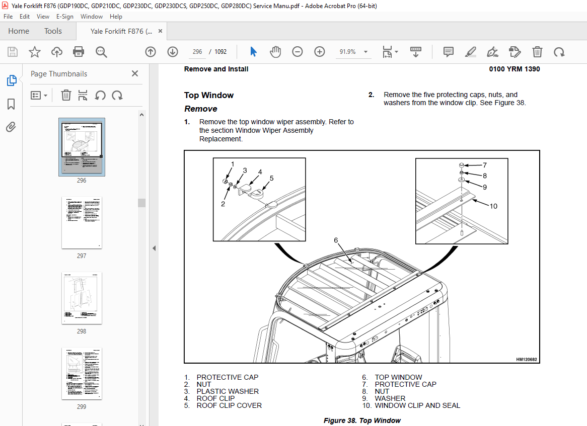
TABLE OF CONTENTS:
Yale Forklift F876 (GDP190DC, GDP210DC, GDP230DC, GDP230DCS, GDP250DC, GDP280DC) Service Manual – PDF DOWNLOAD
524150779 1400YRM0046 (08 2012) US EN 1
toc 1
Differential 1
Safety Precautions Maintenance and Repair 2
General 5
Description 5
Differential Repair 5
Remove 5
Differential Carrier From Axle Housing, Remove 5
Differential and Ring Gear From Differential Carrier, Remove 9
Drive Pinion and Pinion Carrier From Differential Carrier, Remov 11
Disassemble 12
Differential and Ring Gear Assembly, Disassemble 12
Drive Pinion and Pinion Carrier, Disassemble 13
Clean and Inspect 16
Assemble 17
Pinion, Bearings, and Pinion Carrier, Assemble 17
Pinion Bearings, Adjust Preload 17
Press Method 17
Yoke or Flange Method 18
Triple-Lip Seal, Install 19
Pinion Carrier Shim Set, Adjust Thickness (Depth of Pinion) 20
Differential and Ring Gear, Assemble 22
Differential Gears Rotating Torque, Check 24
Differential and Ring Gear Assembly, Install 25
Differential Bearings, Preload Adjust 26
Ring Gear, Runout Check 27
Ring Gear Backlash, Adjust 28
Gear Set, Tooth Contact Pattern Check 30
Thrust Screw, Install and Adjust 33
Install 33
Differential Assembly Into Axle Housing, Install 33
Specifications 34
Troubleshooting 38
tables 1
Table 1 Ring Gear Backlash Adjustment Specifications 29
Table 2 Ring and Pinion Tooth Contact Adjustment 30
Table 3 General Specifications 34
Table 4 Rivet Installation Pressure 34
Table 5 Pinion Adjustment 34
Table 6 Pinion Preload Pressure 35
Table 7 Torque Specifications 36
Table 8 Torque Specifications for Metric Hardware 37
Table 9 Torque Specifications for Metric (Fine) Hardware 37
524150780 1400YRM0944 (08 2012) US EN 41
toc 41
Planetary Drive Axle 41
Safety Precautions Maintenance and Repair 42
General 45
Description 45
Operation 47
Identification 47
Removal 48
Disassembly 48
Planetary Spider and Gearing Assembly GDP80-120DB (GP170-280DB) 49
Planetary Spider and Gearing Assembly GDP130-160EB (GP300-360EB) 50
Wheel End 52
Spindle and Piston Housing 53
Cleaning 54
Clean Ground or Polished Parts 54
Clean Parts With Rough Finish 54
Clean Axle Assemblies 54
Drying Cleaned Parts 54
Corrosion Prevention 54
Parts Inspection 55
Tapered Roller Bearings 55
Bevel Pinion and Ring Gear Sets 56
Main Differential Assembly 56
Axle Shafts 56
Yoke 56
Brakes 56
Repair or Replace Parts 56
Repair Welding 57
Apply Silicone Gasket Material 57
Assembly 57
Spindle and Piston Housing to Axle Housing 57
Wet Disc Brakes 58
Adjust Wheel Bearing Preload 59
Planetary Spider and Gearing Assembly GDP80-120DB (GP170-280DB) 60
Planetary Spider and Gearing Assembly GDP130-160EB (GP300-360EB) 60
Planetary Spider Assembly 61
Installation 62
Fill Wet Disc Brakes With Hydraulic Fluid 62
Torque Specifications 63
Lubrication Specification 64
524150797 8000YRM0231 (02 2023) US EN 67
General 73
Threaded Fasteners 73
Nomenclature, Threads 73
Strength Identification 74
Cotter (Split) Pins 75
Fastener Torque Tables 80
Conversion Table 82
524150797 8000YRM0231 (03 2020) US EN 89
General 93
Threaded Fasteners 93
Nomenclature, Threads 93
Strength Identification 94
Cotter (Split) Pins 95
Fastener Torque Tables 100
Conversion Table 102
524211827 0600YRM1101 (11 2018) US EN 109
Series Code / Model Designation Reference Table 113
General 113
Fault Codes 114
Normal Mode 114
Fault Log Mode 115
Access 115
Exit 115
Clear 115
Electronic Throttle Calibration 115
Electronic Throttle Calibration Procedure 116
Stationary Regeneration Procedure 116
524230692 8000YRM1181 (01 2017) US EN 145
Series Code / Model Designation Reference Table 149
General 150
Weight and Dimensions 150
Loading Procedures 158
Loading A Truck on a Transport 158
Loading Disassembled Components 158
Unloading Procedures 159
Unloading Complete Truck or Basic Truck From Transport 159
Lifting 159
Driving On/Off a Trailer 160
Unloading Disassembled Components 160
Removal of Forks Attached to Basic Truck 160
Removal of Forks Attached to the Carriage 160
Truck Assembly 161
Safety procedures When Working Near the Mast 162
Mast Installation 163
Preparations 163
Adjusting the Tilt Cylinders 165
Connecting the Lift Cylinders 165
Connecting the Mast Supply Hoses 166
Carriage and Forks 167
Installing the Carriage 167
Connecting the Header Hoses to the Carriage 167
Install the Forks 167
Installing Pin-Type Forks 167
Installing Quick Disconnect DFSSFP Forks 169
170
Installing Integrated DFSSFP Forks 170
Adjusting the Carriage 170
Adjusting Header Hose Tension 171
Adjusting the Electrical Cable Tension 172
Installing the Cab Lights 172
Adding the Mast Labels 173
Lubrication Points 173
Pre-Delivery Inspection 174
Empty Seat Engine Shut Down 174
Pre-Delivery Inspection 174
Pneumatic Tires and Wheels 175
Remove Wheels From Lift Truck 175
Remove Tire From Wheel 176
Install Tire on the Wheel 178
Adding Air Pressure to the Tires 180
Solid Rubber Tires, Remove Tire From the Wheel 180
Solid Rubber Tires, Install Tire on the Wheel 182
Install Wheels on Lift Truck 184
Moving and Towing 185
Moving a Disabled Lift Truck 185
Precautions 185
Towing A Lift Truck 186
550033398 0100YRM1459 (12 2018) US EN 189
Series Code / Model Designation Reference Table 193
Description and Operation 193
Heater System 193
General 193
Air Conditioning 194
General 194
Dryer 195
Compressor Lubrication 196
Control Systems, Sensors, and Switches 196
Climate Control 197
Description 197
Service Menu 197
Set Up 198
View 1 and View 2 198
Error List 199
Statistics 199
Exit 199
Temperature Sensors 199
Troubleshooting 199
Water Valve 200
Troubleshooting 200
Remove and Replace 202
Standard Heater Assembly 203
Access 203
Remove 203
Install 204
Standard Heater Parts 205
Heater Core 205
Remove 205
Install 206
Blower 206
Remove 206
Install 207
Water Valve 208
Remove 208
Install 208
Push/Pull Cable 209
Water Valve Cable 209
Remove 209
Install 209
Heater/Air Conditioner Assembly 210
Remove 210
Install 211
Heater/Air Conditioner Parts 211
Vent Door 211
Remove 211
Install 212
Heater Core 212
Remove 212
Install 213
Evaporator Core 214
Remove 214
Install 215
Blower 216
Remove 216
Install 216
Thermostat 217
Remove 217
Install 218
Water Valve 218
Remove 218
Install 219
Air Conditioning Technical Detail 220
550033400 0100YRM1390 (12 2018) US EN 223
Series Code / Model Designation Reference Table 231
General 231
Description of Operation 233
Cab Structure 233
Cab Tilt System 233
Cab Tip-Up System 235
Tilting the Cab 236
Raising 236
Lowering 237
Remove and Install 238
Cab Door Assembly 238
Cab Door 238
Remove 238
Install 238
Door Hinge 239
Remove 239
Install 239
Door Latch 240
Remove 240
Install 240
Door Handle 240
Remove 240
Install 240
Door Release 241
Remove 241
Install 241
Door Push Button 241
Remove 241
Install 242
Cab Tilt System 242
Electric Tilt Pump 242
Remove 242
Install 242
Hand Tilt Pump 242
Remove 242
Install 243
Cab Tilt Cylinder 244
Remove 244
Disassemble 244
Clean 246
Inspect 246
Assemble 246
Install 247
Latch 247
Remove 247
Install 248
Brake and Inching Pedal 249
Remove 249
Install 249
Accelerator Pedal and Sensor 250
Remove 250
Install 250
Adjust Sensor 250
Seat Assembly 250
Seat 250
Remove 250
Install 251
Seat Cushion 251
Remove 251
Install 252
Back Cushion 252
Remove 252
Install 252
Seat Suspension Replacement 252
Boot Replacement 252
Power Assist Armrest 276
Release Cable 276
Remove 276
Install 276
Gas Spring 276
Remove 276
Install 277
Joystick 277
Remove 277
Install 277
Electrical Levers 277
Remove 277
Install 278
Armrest Rocker Switches 278
Remove 278
Install 278
Armrest Top Cover 278
Remove 278
Install 278
Instrument Panel 279
Key Switch 279
Remove 279
Install 279
12V Power Socket 279
Remove 279
Install 279
Electric-Operated Heat Control and Air Recirculation Control (Airco Only) 280
Remove 280
Install 280
Cable-Operated Heater Control (Heater Only) 281
Remove 281
Install 281
Air Conditioning Switch Replacement 281
Instrument Panel Rocker Switches Replacement 281
Parking Brake Switch 282
Remove 282
Install 282
Indicator Display Replacement 282
Instrument Panel Top Console 282
Remove 282
Install 283
Steering Wheel and Column Assembly 283
Steering Wheel and Horn 283
Remove 283
Install 285
Steering Column Assembly 285
Remove 285
Install 286
Adjustment Handle 286
Remove 286
Install 286
Main Warning Lights 287
Remove 287
Install 287
Shift Lever 287
Remove 287
Install 287
Turn Signal Lever 287
Remove 287
Install 287
Window Wipers 288
Window Wiper Assembly Replacement 288
Remove 288
Install 288
Window Wiper Motor Replacement 288
Front Window Wiper Motor 288
Install 288
Rear Window Wiper Motor Assembly 289
Remove 289
Install 289
Top Window Wiper Motor Assembly 289
Remove 289
Install 289
Window Washer System 290
Window Washer Reservoir and Pumps 290
Remove 290
Install 290
Window Washer Hoses 291
Hoses for Top and Rear Window 291
Install 292
Window Washer Spray Nozzles 292
Front Window 292
Remove 292
Install 292
Rear Window 293
Remove 293
Install 293
Top Window 293
Remove 293
Install 293
Window Replacement 293
Front Window 295
Remove 295
Install 295
Rear Window 295
Remove 295
Install 295
Top Window 296
Remove 296
Install 296
Door, Upper/Lower Window 297
Remove 297
Install 297
Sliding Window and Sliding Tracks 297
Remove 297
Install 299
Weather Strip Replacement 299
Window Stopper Replacement 299
Window Seal Replacement 300
Sliding Window Frame 300
Remove 300
Install 300
Floor Mat 300
Front Floor Mat 300
Remove 300
Install 301
Rear Floor Mat 301
Remove 301
Install 302
Radio Console 302
Remove 302
Install 302
Air Duct Replacement 303
Remove Front 303
Remove Rear 303
Install 304
Accessories 304
Mirror Replacement 304
Sunshade Replacement 304
Top 304
Rear 305
Map Light Replacement 305
Interior Fan Replacement 305
Training Seat 305
Field Installation 305
Remove 305
Label Replacement 306
Checks and Adjustments 306
Check Oil Level for Cab Tilt System 306
Door Striker Pin Adjustment 307
Brake Pedal Adjustment 307
Dry Brake 307
Wet Brake 308
Inching Pedal Adjustment 308
Inching Pedal Sensor Adjustment 308
Sensor Adjustment Using Dana Dashboard Software 308
Sensor Adjustment using the APC200 Display 309
Sensor Adjustment for Trucks with ZF Transmission 310
Inching Pedal Sensor Calibration 310
Sensor Calibration using Dana Dashboard Software 310
Sensor Calibration using APC200 Display 310
Sensor Calibration for Trucks with ZF Transmission 311
550035498 2200YRM1481 (08 2012) US EN 315
toc 315
Hydraulic Control System 315
Safety Precautions Maintenance and Repair 316
General 319
Description 319
Control Valve 319
Analog Inputs 320
Levers and Joysticks 320
Sensors 321
Temperature Sensor 321
Pressure Sensor 321
Digital Inputs 321
Switches 321
Interrupts 321
CAN Bus Communication 322
Output Signals 322
Analog Outputs 322
Digital Outputs 322
Programmed Features 322
Anti-Stall (Standard) 322
Temperature Protection (Standard) 322
Low Temperature Protection (Standard) 323
High Temperature Protection (Optional) 323
Dynamic Control (Optional) 323
Loaded Speed Reduction (Optional) 323
Settings 323
Adjustable Parameters 323
Truck Configuration Screen 323
Mode Definition Responsiveness (Smooth, Medium, and Rapid) 323
Set Default Flow Settings Screen 323
Features Screen 323
Loaded Speed Reduction Screen 323
Flow Settings Screen 324
General Functions of the Interface 324
Main Functional Requirements 324
What is Needed for the Hydraulic User Interface Program 324
Installation of the Program 324
Start Screen 327
Reminder Screen 328
Basic Screen Layout of the Hydraulic User Interface Program 329
Truck Configuration Screen 330
Mode Definition Screen 332
Default Flow Settings Screen 333
Load Moment Interrupt Screen 334
Features Screen 335
Dynamic Control Screen 336
Loaded Speed Reduction Screen 337
Temperature Protection Screen 338
Anti-Stall Screen 339
Calibration Screen 340
Calibrating the Connected Levers/Joystick Without the Interface 340
Calibrating the Connected Levers/Joystick With the Interface Sof 340
Profile Configuration Screen 341
Flow Settings Screen 342
Valve Settings Screen 343
Diagnostic Screen 344
Active Errors Screen 345
Error History Screen 346
All Parameters Screen 347
Installing the Hydraulic Controller Software and Read-Only Param 348
Calibration 351
Calibrating the Lever With the Hydraulic User Interface Program 351
Calibrating the Joystick With the Hydraulic User Interface Progr 351
Calibrating the Lever Without the Hydraulic User Interface Progr 351
Calibrating the Joystick Without the Hydraulic User Interface Pr 351
Fault Codes 352
Controller Pinning 362
tables 315
Table 1 Temperature and Maximum Engine Speed 323
Table 2 Hydraulic User Interface Program Overview 325
Table 3 Parameters 332
Table 4 Temperature/Rpm Table 338
Table 5 Fault Codes 352
Table 6 Fixed PT 362
Table 7 Alternating PT 364
Table 8 Empty Container Handler (ECH) 366
Table 9 XML Parameter File Content 367
550035502 1300YRM1455 (11 2018) US EN 373
Series Code / Model Designation Reference Table 377
General 377
Description 377
General 377
Clutch 382
Operation 382
Hydraulic Operation 382
Clutch Valve 383
Cooling and Lubrication 384
Control System 385
Transmission Control Unit (TCU) 386
Operating Modes 386
Normal Mode 386
Substitute Clutch Control 386
Limp-Home Mode 386
Transmission Shut Down Mode 386
TCU Shut Down Mode 386
Transmission Exceed Codes 386
Self-Test 387
Fault Codes 387
Description 387
Fault Log Mode 387
Access 387
Exit 388
Clear 388
Fault Log Memory 388
Fault Rectification 388
Hydraulic Control Valve 389
Hydraulic Control Valve Repair 390
Solenoid Replacement 390
Pressure Check 390
Pressure Specifications 391
Speed and Temperature Sensors 391
Speed Sensors 392
Test 393
Temperature Sensors 393
Shift Lever 393
PedalFoot Directional Control 393
ZF Transmission Test and Calibration 394
Transmission Test and Calibration 394
Precautions 394
Stall Test 394
Description 394
Stall Test Procedure 394
Inch Pedal Calibration 395
Description 395
Calibration 395
Brake and Inch Pedal Adjustment 395
Inch Sensor Adjustment 395
Inch Pedal Calibration 396
Preparation 396
Calibration Procedure Using the Calibration Switch 396
Calibration Procedure Using the Testman software 396
Inch Pedal Calibration Fault Codes 396
Clutch Calibration 397
Description 397
Clutch Calibration Procedure 398
Manual Clutch Calibration Procedure 398
Testman Clutch Calibration Procedure 399
Testman 399
Description 399
Connection 400
Truck Configuration 400
Configuration 400
Limitations 400
Capacities and Specifications 401
Electrical Specifications 401
Transmission Control Unit Diagram 401
ZF Transmission Fault Codes 403
Transmission Exceed Codes 403
Testman Fault Codes 404
550035503 1300YRM1456 (12 2015) US EN 415
Series Code / Model Designation Reference Table 419
Special Tools List 420
Transmission Repair 421
Remove 421
Disassemble 425
Clean and Inspect 464
Housings 465
Oil Seals and Gaskets 465
Bearings 465
Gears and Shafts 465
Assemble 466
Transmission Oil Filter Assembly Replacement 513
Clean 514
Inspect 514
Install 515
Control Valve Replacement 520
Remove 520
Install 521
Control Valve Repair 522
Disassemble 522
Clean 526
Inspect 526
Assemble 527
550035504 1600YRM1479 (08 2012) US EN 535
toc 535
Steering System 535
Safety Precautions Maintenance and Repair 536
General 541
Basic Principles of Flow Control Systems 541
Basic Principles of Flow Control Systems 541
Orifice (Fixed/Variable) 541
Basic Principle 541
Pressure Compensated Flow Control Valve 542
Basic Principle 542
Pressure Compensated Flow Control Valve Functional Description 542
Priority Valve 542
Basic Principle 542
Priority Valve Functional Description 543
Load Sense (LS) 544
Basic Principle 544
Load Sense Functional Description 544
Example 1 545
Example 2 545
Basic Principles of Pressure Control Systems 545
Basic Principles of Pressure Control Systems 545
Direct Acting Relief Valves 546
Basic Principle 546
Direct Acting Relief Valve Functional Description 546
Two-Stage Relief Valve (Pilot Operated Relief Valve) 546
Basic Principle 546
Two-Stage Relief Valve (Pilot Operated Relief Valve) Functional 546
Unloading Valve (Accumulator Charging Valve) 547
Basic Principle 547
Unloading Valve (Accumulator Charging Valve) Functional Descript 547
Counterbalance Valve 548
Basic Principle 548
Counterbalance Valve Functional Description 549
Pressure Reducer Valve 549
Basic Principle 549
Pressure Reducer Valve Functional Description 549
Steering System Main Component Identification 550
Description and Operation 553
Steering System 553
Introduction 553
Description 553
Hydraulic Oil Flow Path 553
Priority Valve 553
Fundamentals 553
Description 553
Operation 553
Component Validation for Correct Operation 554
Steering Control Unit 554
Description 554
Steering Control Valve 554
Fundamentals 554
Operation 554
Component Validation for Correct Operation 554
Hand Pump 555
Fundamentals 555
Operation 555
Component Validation for Correct Operation 555
LS Relief Valve 555
Fundamental 555
Operation 555
Component Validation for Correct Operation 555
Shock Valve 555
Fundamental 555
Operation 555
Component Validation for Correct Operation 555
Steering Axle 555
Steering Control Unit 556
Remove 556
Install 557
Hydraulic Troubleshooting Flowcharts 558
Hydraulic Pressure Checks Preparation 558
Steering Relief Pressure Check 558
Pressure Check, Port MLS1 and MLS2 on the Main Control Valve 559
Steering Wheel Lock to Lock Check 559
Flowchart 560
Hydraulic Pressure Checks for Troubleshooting Flowcharts 561
Hydraulic Pressure Checks Preparation 561
Condition Check, Shuttle Valve L and M in the Main Control Valve 561
Condition Check, Logic Element N in the Main Control Valve 562
Condition Check, Priority Valve on the Main Control Valve 562
Steering Cylinder 562
Remove and Disassemble 562
Clean and Inspect 564
Assemble and Install 564
Steering Axle Assembly 566
Steer Axle 566
Remove 566
Install 566
Wheels and Hubs 568
Remove and Disassemble 568
Clean 568
Inspect 568
Assemble and Install 568
Spindles and Bearings 569
Remove 569
Clean 570
Assemble and Install 570
Tie Rods 570
Remove 570
Clean 570
Install 570
Torque Specifications 572
Steering Control Unit 572
Steering Axle 572
Wheel Nuts 572
Steering Cylinder 572
tables 535
Table 1 Definition of Terms 541
Table 2 Definition of Terms 545
Table 3 Internal Components of the Steering Control Unit 554
Table 4 Flowchart 560
550035505 1800YRM1498 (03 2013) US EN 575
toc 575
Brake and Hydraulic Cooling System 575
Safety Precautions Maintenance and Repair 576
General 583
Basic Principles of Flow Control Systems 583
Basic Principles of Flow Control Systems 583
Orifice (Fixed/Variable) 584
Basic Principle 584
Pressure Compensated Flow Control Valve 584
Basic Principle 584
Pressure Compensated Flow Control Valve Functional Description 584
Priority Valve 585
Basic Principle 585
Priority Valve Functional Description 585
Load Sense (LS) 586
Basic Principle 586
Load Sense Functional Description 586
Example 1 587
Example 2 587
Basic Principles of Pressure Control Systems 587
Basic Principles of Pressure Control Systems 587
Direct Acting Relief Valves 588
Basic Principle 588
Direct Acting Relief Valve Functional Description 588
Two-Stage Relief Valve (Pilot-Operated Relief Valve) 589
Basic Principle 589
Two-Stage Relief Valve (Pilot Operated Relief Valve) Functional 589
Unloading Valve (Accumulator Charging Valve) 590
Basic Principle 590
Unloading Valve (Accumulator Charging Valve) Functional Descript 590
Counterbalance Valve 591
Basic Principle 591
Counterbalance Valve Functional Description 591
Pressure Reducer Valve 592
Basic Principle 592
Pressure Reducer Valve Functional Description 592
Brake System Main Component Identification 592
Description 598
Brake Pressure System 598
Main System 598
Introduction 598
Service Brakes 598
Park Brake 598
Description 598
Hydraulic Oil Flow Path 598
Brake Accumulator Charging System 598
Service Brake System 599
Park Brake System 599
Priority Valve 599
Fundamentals 599
Description 599
Operation 599
Component Validation for Correct Operation 599
Brake Control Manifold 599
Description 599
Orifice (F) 600
Fundamentals 600
Description 600
Operation 600
Component Validation for Correct Operation 601
Unloading Valve 601
Fundamentals 601
Operation 601
Component Validation for Correct Operation 601
Screen 601
Description 601
Component Validation for Correct Operation 601
Check Valve 601
Description 601
Component Validation for Correct Operation 601
Pressure Reducer Valve 601
Fundamentals 601
Operation 601
Component Validation for Correct Operation 601
Park Brake Selector Valve 601
Fundamentals 601
Operation 601
Component Validation for Correct Operation 601
Brake Accumulator 602
Fundamentals 602
Operation 602
Component Validation for Correct Operation 602
Brake Treadle Valve 602
Fundamentals 602
Description 602
Operation 602
Wet Disc Brake Cooling System 602
Main System 602
Introduction 602
Description 602
Hydraulic Oil Flow Path 602
Gear Pump 603
Fundamentals 603
Operation 603
Brake Cooling Valve 603
Description 603
Operation 603
Thermostatic Bypass Valve 603
Fundamental 603
Operation 603
Component Validation for Correct Operation 603
Brake Flow Distribution Manifold 603
Fundamentals 603
Operation 603
Component Validation for Correct Operation 604
Hydraulic Oil Cooler Core 604
Fundamentals 604
Operation 604
Brake Return Line Filter ( E876 & E877 Only) 605
Operation 605
Cooling System Air Brakes 605
Main System 605
Description 605
Hydraulic Oil Flow Path 605
Component Explanation 605
Brake Treadle Valve Repair 606
Remove 606
Install 606
Accumulator 607
Remove 607
Disassemble 608
Clean 609
Inspect 609
Repair 610
Assemble 610
Install 610
Pre-Charge Filling 611
Parking Brake 612
Parking Brake Caliper 612
Remove 612
Disassemble 613
Clean and Inspect 613
Assemble 615
Install 615
Parking Brake Caliper Pads 615
Remove 615
Install 616
Parking Brake Bleed 616
Parking Brake Emergency Release 617
Brake Flow Distribution Manifold 617
Remove 617
Pressure Relief Valve 619
Disassemble 619
Clean and Inspect 619
Assemble 619
Install 619
Brake Control Manifold 620
Remove 620
Orifices F and G 621
Disassemble 621
Assemble 621
Orifice H 621
Disassemble 621
Assemble 621
Unloading Valve (B) 621
Disassemble 621
Assemble 621
Screen 621
Disassemble 621
Assemble 621
Check Valve (E) 622
Disassemble 622
Assemble 622
Pressure Reducer Valve (C) 622
Disassemble 622
Assemble 622
Park Brake Selector Valve (A) 623
Disassemble 623
Assemble 623
Install 623
Brake Cooling Valve 624
Remove 624
Install 624
Filter Restriction Indicator (Optional) 625
Remove 625
Install 625
Filter 626
Remove 626
Install 626
Brake Return Line Filter ( E876 & E877 Only) 627
Brake Return Line Filter Assembly 627
Remove 627
Install 628
Filter 628
Remove 628
Install 628
Gear Pump 628
Remove 628
Disassemble 628
Clean 630
Inspect 630
Assemble 631
Install 631
Hydraulic Troubleshooting Flowcharts 632
Mechanical Troubleshooting 636
Checks and Adjustments 638
Hydraulic Pressure Checks Preparation 638
Park Brake Selector Valve Check 638
Park Brake Selector Valve Coil Check 638
Accumulator Pre-Charge Check 638
Parking Brake Adjustment 639
Condition Check, Shuttle Valve L in the Main Control Valve 640
Condition Check, Shuttle Valve N in the Main Control Valve 640
Condition Check, Priority Valve on the Main Control Valve 640
Pressure Check, Port MLS1 641
Torque Specifications 641
Hydraulic Hose Torque Specifications 641
tables 575
Table 1 Definition of Terms 583
Table 2 Definition of Terms 587
Table 3 Internal Components of the Brake Control Manifold 600
Table 4 Internal Components of the Brake Cooling Valve 604
Table 5 Low Brake Pressure Warning Is Intermittent or Constantl 633
Table 6 Service Brake Is Soft or Spongy 634
Table 7 Hydraulic Oil is Overheating 635
Table 8 Parking Brake Will Not Disengage With the Parking Brake 635
Table 9 Lining-to-Disc Clearance 640
550035506 1900YRM1478 (11 2018) US EN 645
Series Code / Model Designation Reference Table 653
Fundamentals 653
Basic Principles of Flow Control Systems 653
Orifice (Fixed/Variable) 653
Basic Principle 653
Pressure Compensated Flow Control Valve 654
Basic Principle 654
Pressure Compensated Flow Control Valve Functional Description 655
Priority Valve 655
Basic Principle 655
Priority Valve Functional Description 655
Load Sense (LS) 656
Basic Principle 656
Load Sense Functional Description 657
Example 1 657
Example 2 657
Basic Principles of Pressure Control Systems 657
Direct Acting Relief Valves 658
Basic Principle 658
Direct Acting Relief Valve Functional Description 658
Two-Stage Relief Valve (Pilot-Operated Relief Valve) 658
Basic Principle 658
Two-Stage Relief Valve (Pilot-Operated Relief Valve) Functional Description 659
Pilot-Operated Selector Valves 659
Fundamentals 659
Function Description 660
Pump Pressure Free Flow Side 660
Function Pressure Blocked Flow Side 660
Unloading Valve (Accumulator Charging Valve) 661
Basic Principle 661
Unloading Valve (Accumulator Charging Valve) Functional Description 661
Counterbalance Valve 662
Basic Principle 662
Counterbalance Valve Functional Description 662
Pressure Reducer Valve 663
Basic Principle 663
Pressure Reducer Valve Functional Description 663
Description and Operation 663
Component Location and Identification 664
Main Control Valve 670
Introduction 670
Flow Path 670
Main Manifold 670
Introduction 670
Priority Valve (A) 670
Fundamentals 670
Description 671
Operation 671
Component Functionality Test 671
Check Valve (I) 671
Function Description 671
Function Operation 671
Component Functionality Test 671
Pilot Supply Circuit 671
Function Description 671
Pilot Supply Valve (F) 671
Fundamentals 671
Function Description 671
Function Operation 671
Component Functionality Test 671
Lift Pressure Selector Valve (B) 672
Function Description 672
Function Operation 672
Component Functionality Test 672
Check Valve (K) 672
Function Description 672
Component Functionality Test 672
Check Valve (Q) 672
Function Description 672
Component Functionality Test 672
Screen (O) 672
Function Description 672
Component Functionality Test 672
Relief Valve 672
Function Description 672
Load Sense Relief Valve (H) 672
Fundamentals 672
Functional Operation 672
Component Functionality Test 672
Pressure Controller on Pump 673
Fundamentals 673
Functional Operation 673
Component Functionality Test 673
Full Flow Relief Valve (C) and (G) 673
Fundamentals 673
Functional Operation 673
Component Functionality Test 673
Shuttle Valve (L) and (M) 673
Function Description 673
Component Functionality Test 673
Logic Valve (N) 674
Function Description 674
Function Operation 674
Load Sense Selector Valve (D) 674
Function Description 674
Component Functionality Test 674
Directional Control Valve Section 674
Functional Operation (System Level) 674
Directional Control Valve 675
Fundamentals 675
Description 675
Functional Operation 675
Electrical Actuation Module (Solenoid End Cap) 675
Functional Operation 675
Component Functionality Test 676
Lift Function 676
Function Description 676
Pilot-Operated Check Valve 676
Fundamentals 676
Function Description 677
Function Operation 677
Emergency Lowering Valve (LH Lift Section ONLY) 677
Function Description 677
Lowering Control Valve 677
Fundamentals 677
Function Description 677
Tilt Function 677
Function Description 677
Impact Relief Valve 678
Fundamentals 678
Function Description 678
Counterbalance Valve 678
Fundamentals 678
Function Description 678
Auxiliary Function 678
Function Description 678
Carriage Valve Bank 678
Introduction 678
Functional Operation 679
Inlet Module 679
Directional Control Valve Section 679
Directional Control Valve 679
Electrical Actuation Module (Solenoid End Cap) 680
Variable Displacement Pump 680
Function Description 680
Basic Functional Operation 681
Pressure Control Valve 681
Fundamentals 681
Operation 681
Load Sense Pressure Regulator 681
Fundamentals 681
Functional Operation 681
Repair 682
Main Control Valve 682
Remove 682
Clean 687
Inspect 687
Assemble 687
Install 687
Priority Valve (A) 690
Remove 690
Clean 690
Inspect 691
Component Functionality Test 691
Install 691
Check Valve (K) 691
Remove 691
Clean 691
Inspect 691
Component Functionality Test 691
Install 691
Check Valve (I) 691
Remove 691
Clean 691
Inspect 692
Component Functionality Test 692
Install 692
Check Valve (Q) 692
Remove 692
Clean 692
Inspect 692
Component Functionality Test 692
Install 692
Screen Cartridge (O) 692
Disassemble 692
Component Functionality Test 692
Assemble 692
Shuttle Valves (L) and (M) 693
Remove 693
Clean 693
Inspect 693
Component Functionality Test 693
Install 693
Logic Valve (N) 694
Remove 694
Clean 694
Inspect 694
Component Functionality Test 694
Install 694
Full Flow Relief Valve ©) (Relief Spool) 694
Remove 694
Clean 694
Inspect 695
Assemble 695
Install 695
Pilot Supply Valve (F) 695
Remove 695
Clean 695
Inspect 695
Assemble 695
Component Functionality Test 695
Install 695
Load Sense (LS) Relief Valve (H) and Full Flow Relief Valve (G) 695
Remove 695
Clean 695
Inspect 696
Component Functionality Test 696
Install 696
Load Sense Relief Valve (H) Adjustment 696
Full Flow Relief Valve (G) Adjustment 696
Load Sense Selector Valve (D) 696
Remove 696
Clean 696
Inspect 697
Assemble 697
Install 697
Lift Pressure Selector Valve (B) 697
Remove 697
Clean 697
Inspect 698
Assemble 698
Install 698
Variable Displacement Pump (Primary and Secondary) 698
Remove 698
Clean 700
Inspect 700
Assemble 700
Install 701
Tilt Cylinder 702
Remove 702
Disassemble 702
Clean 702
Assemble 702
Install 703
Tilt Cylinder Leak Check 703
Tilt Cylinder Stroke and Mast Tilt Angle Adjustment 704
Counterbalance Valves 704
Remove 704
Clean 705
Inspect 705
Assemble 705
Install 705
Carriage Valve Bank 705
Remove 705
Clean 708
Inspect 709
Assemble 709
Install 709
Electrical Actuation Module 709
Remove 709
Clean 709
Inspect 709
Assemble 709
Install 710
Emergency Lowering Valve (Left Slice Only) 710
Remove 710
Clean 711
Inspect 711
Install 711
Load Sense and Pressure Controller Valve on Pump 711
Remove 711
Clean 711
Inspect 711
Assemble 712
Install 712
Adjustment of Pressure Controller on Pump 712
Adjustment of Load Sense Controller on the Secondary Variable Pump 713
Adjustment of Load Sense Controller on the Primary Variable Pump 714
Lowering Control Valve 715
Remove 715
Clean 716
Inspect 716
Install 716
Directional Control Valve 716
Remove 716
Clean 716
Inspect 716
Assemble 717
Install 717
Manual End Cap 717
Remove 718
Clean 718
Inspect 718
Assemble 718
Install 718
Troubleshooting 718
Lift, Tilt, and/or Aux function does not move when applied Steering is operating normal 718
The truck is not
capable to lift
rated load at expected
max lift
speed 719
Tilt function
shakes 719
It is not
possible to
lower the
mast with
ignition key
turned to
ON 720
Steer and
brake accumulator
charge
function
does not operate 720
The truck is
hydraulically
loaded
during engine
start
Accumulator
charge
and steering
is possible
during
XMSN calibration 720
Torque Specifications 720
Torque Specifications 720
550061801 0100YRM1594 (11 2015) US EN 723
General 727
Description 727
Air Cleaner 728
Air Cleaner Assembly, Tier 3/Stage III A, F876/F877 729
Remove 729
Install 729
Air Cleaner Assembly, Tier 4i/Stage III B, F876/F877 730
Remove 730
Install 731
Exhaust System 732
Exhaust Assembly, Tier 3/Stage III A, F876/F877 732
Remove 732
Install 733
Exhaust Assembly, Tier 4i/Stage III B, F876/F877 733
Remove 733
Install 735
Hood Assembly 736
Remove 736
Install 738
Hydraulic Tank 738
Remove 738
Inspect 741
Clean 741
Additional Preparations for Repair 741
Repair 742
Preparations for use After Repair 742
Install 742
Fuel Tank 744
Remove 744
Repair 748
Install 748
Cab 749
Raising and Lowering Cab 749
Raise Cab 749
Lower Cab 750
Cab Repair 750
Remove 750
Install 752
Oil Filling for Cab Tilt System 752
Engine 753
Remove 754
Install 760
Counterweight 763
General 763
Remove 763
Install 764
Label Replacement 765
550061806 0700YRM1595 (02 2017) US EN 769
General 773
773
Cooling System Description 773
Cooling Cores 773
Fan 774
Fan Clutch 774
Fan Clutch Engagement 774
Shroud 776
Engine Cooling System 776
Water Pump 776
Thermostat 776
Expansion Tank And Radiator Cap 777
Cab Heater 778
Coolant 778
DEF Heater 780
Charge Air Cooling System 780
Transmission Oil Cooling System 780
Hydraulic Oil Cooling System 780
Hydraulic Oil Cooling 780
Oil Filtration and Oil Cooling 782
Brake Cooling 782
Hydraulic Control System 782
Service and Repair 782
Cooling System Checks 783
Basic Checks 783
Coolant Quality Checks 783
Coolant Flow Checks 784
Thermostat 784
Water Pump 785
Cooling Core Efficiency 785
Cooling Core Flow Restrictions 786
Engine Leak Tests 786
External Leak Test 786
Check for Coolant Leak Into The Engine Oil Sump 787
Combustion Leak Test 788
Engine Cooling System Maintenance 788
Draining the Engine Cooling System 788
Filling the Engine Cooling System 789
Flushing the Engine Cooling System 789
Cleaning the Engine Cooling System 790
Remove and Replace 790
Fan 790
Remove 790
Install 790
Drive Belt 791
Remove 791
Install 791
Belt Tensioner 792
Inspect 792
Remove 792
Install 792
Water Pump 793
Inspect 793
Remove 793
Install 793
Thermostat 794
Remove 794
Inspect 794
Install 794
Cooling Core Assembly 794
Remove 795
Cooling Cores 800
Disassembly 800
Assembly 800
Install 800
550061811 2200YRM1592 (09 2013) US EN 805
toc 805
Electrical System 805
Safety Precautions Maintenance and Repair 806
General 809
Electrical Schematic and System Description 810
Electrical Schematic 810
Schematic Location Number 813
Electrical Components 813
Electrical Wires 813
Wire Identification Number 813
Electrical Wire Colors 814
Wire Harnesses 814
Harness Interconnection 815
Electrical Connectors 815
Connector Types 815
Connector Identification 815
Connector Pin Numbers 816
Connector Description 816
Fuses 816
Relays 822
Flyback Diodes 823
CAN (Controller Area Network) 823
Diagnostic 824
Troubleshooting 824
Instrument Panel 824
General Fault Finding 827
Preparation 827
Define the Problem Area 827
Identify Possible Causes of Malfunction 827
Determine the Most Probable Cause 827
Fuse Check 827
Wiring Check 827
Component Check 827
Repair and Test 827
Wire Harness Identification and Connector Location 828
tables 805
Table 1 Electrical Schematic Index, Tier III 811
Table 2 Electrical Schematic Index, Tier IV 811
Table 3 Function ID Numbers 813
Table 4 Electrical Wire Colors 814
Table 5 Harnesses by Option 814
Table 6 Connector Types 815
Table 7 Legend for Starter and Grid Heater Relays 818
Table 8 Flyback Diodes 823
Table 9 Legend for Figure 7, Figure 8 and Figure 9 826
Table 10 Connector Overview 828
Table 11 Legend for Figure 10 and Figure 11 842
Table 12 Legend for Figure 12 845
550061816 8000YRM1591 (10 2013) US EN 857
550061821 8000YRM1593 (07 2019) US EN 931
General 937
Serial Number Data 937
Truck Handling Procedures 938
Moving and Towing a Lift Truck 938
Precautions 938
Moving the Truck 938
Putting a Lift Truck on Blocks 939
Raising the Drive Tires 939
Raising the Steering Tires 939
Cleaning a Lift Truck 940
Safety Procedures Before Starting Maintenance 941
Making Checks From the Driver Seat with Engine Running 941
Fire Hazard 941
Hydraulic Service Switch 942
Transmission Calibration Switch 942
Wait 100 Seconds Before Disconnecting Battery 942
Periodic Maintenance Schedule 942
Daily Inspection 943
Daily Condition Checks 943
Daily Fluid Level Checks 944
Daily Checks from the Driver Seat with Engine Running 945
Initial Inspection 946
First Inspection after First 100 Hours of Operation 946
Periodic Maintenance 946
Inspect and Adjust 946
Lubricate 950
Change 950
Periodic Maintenance Procedures 952
Air Conditioning System 952
Attachment 952
Brake System Accumulator 952
Brake Cooling Filter 952
Cab Air Filter 953
Cab Door Hinges 953
Control Levers, Switches, and Pedals 953
Cooling System 953
Coolant Hoses 953
Coolant Level 954
Coolant Quality 954
Cooling Fan 954
Cooling Fan Drive Belt 955
Cooling Fan Drive Belt Tensioner and Pulleys 955
Bearing Condition 955
Pulley Alignment 955
Tensioner Condition 955
Crankcase Breather 956
Drive Axle and Differential 957
Check Oil level 957
Change Oil 957
Drive Shaft 957
Engine Air Filter 957
Engine Air Intake Piping and Charge Air Piping 958
Engine and Transmission Mounts 958
Engine Compartment 958
Engine Oil 958
Engine Oil Level 958
Engine Oil and Engine Oil Filter 959
Engine Valve Adjustment 959
Fault Codes 962
Forks 962
Fork Pins, Carriage Pins, and Carriage Sliding Surfaces 963
Frame, Mast, Carriage and Attachment 963
Fuel, Oil or Coolant Leaks 964
Fuel Filter and Water Separator Filter 964
Header Hose Assembly 964
Horn, Gauges, Lights, Alarms and Control System 965
Hydraulic System Oil 965
Hydraulic Oil Testing Procedures 966
Hydraulic Oil Replacement 966
Hydraulic Tank Breather 967
Hydraulic Tank Return Filter 967
Inching Pedal Sensor Calibration 968
Lift Chains 968
Check and Lubricate Lift Chains 968
Adjust Lift Chains 968
Inspect Lift Chains 969
Chain Elongation 969
Lift Chain Wear and Damage 970
Lift System Accumulator (Optional) 970
Load Rollers 970
Carriage Load Rollers 970
Inner Mast Load Rollers 971
Mast, Carriage, and Attachment 971
Mast Pivot Pins 971
Operator Presence System 971
Operator Restraint System 971
Seat Belt and Seat Rails 971
Steering Column Latch 972
Parking and Service Brakes 972
Radiator Assembly 973
Steering Axle Grease Fittings 973
King Pins 973
Tie Rod Pins 973
Steering System 973
Steering Wheel Hub Bearings 973
Remove and Disassemble 973
Clean and Inspect 973
Assemble and Install 974
Tilt Cylinder Pivot Pins 974
Transmission 974
Transmission Clutch Calibration 974
Transmission Oil Level 975
Transmission Oil and Oil Filter 975
Vibration Damper 976
Warning and Safety Labels 976
Windows and Mirrors 976
Windshield Washer Fluid Level 976
Wheels and Tires 977
Wheels, Tires, and Tire Pressure 977
Remove Wheels from Lift Truck 978
Adding Air Pressure to Pneumatic Tires 984
Install Wheels on Lift Truck 989
Capacities and Specifications 990
Approved Fuel and Engine Oils 990
Approved Oils, Fluids, and Grease 990
Engine Oil Viscosity 991
Lift Chain Lubricant Requirements 991
Fuses and Relays 991
Side Console 992
Relays 995
550061826 8000YRM1596 (10 2016) US EN 997
Counterweight Weights 1001
Lift Truck Weights 1002
Capacities 1002
Engine Specifications 1003
Hydraulic System 1004
Electrical System 1004
Tire Sizes 1005
Mast Speeds 1005
Torque Specifications, General 1007
Transmission ZF 1007
Driveline and Axle 1007
Counterweight 1007
Differential 1007
Brakes – Wet 1007
Steering 1007
Wheel Nuts 1007
Hydraulic System 1008
Mast 1008
Carriage 1008
Tilt Cylinders 1008
Wiper Arms, Front 1009
Torque Specifications, Cummins Diesel 1009
Lubrication System 1009
550088524 4000YRM1647 (07 2016) US EN 1013
Series Code / Model Designation Reference Table 1019
General 1019
Description And Operation 1019
Mast System 1019
Tilting 1019
Lifting 1020
Operation 1020
Pilot Operated Check Valves 1021
Gland Lubrication 1022
Emergency Lowering Valve 1022
Operation 1022
Lift Chains 1023
Elongation Through Wear 1023
Speed of Wear 1023
Plate Height Wear 1024
Lubrication 1024
Restoring The Oil Film 1024
Maintenance 1024
Maintaining The Presence of Oil 1025
Corrosion Protection 1025
Requirements for Chain Lubricant 1025
Load Rollers 1026
Bearing Blocks 1026
Carriage 1027
Standard Carriage with Manual Fork Positioning 1027
Standard Carriage with Hydraulic Fork Positioning 1027
Dual Function Side Shift and Fork Positioning (DFSSFP) Carriage 1028
Integral Side Shift 1028
Carriage Valve 1029
Alternating Pressure and Tank (P & T) 1029
Fixed Pressure and Tank (P & T) 1029
Flow Divider for Simultaneous Fork Positioning 1029
Valve for Dual Function with Side Shift and Fork Positioning (DFSSFP) 1031
Fixed Pressure and Tank System (Fixed P & T) 1033
Forks 1035
Safety Procedures When Working Near Mast 1036
Before Starting Repairs to the Hydraulic System, Always: 1037
Remove and Replace 1037
Forks 1037
Remove 1037
Install 1038
Fork Guide And Fork Pin 1039
Remove 1039
Install 1039
Carriage 1040
1040
Remove 1040
Install 1041
Carriage Bearing Blocks 1042
Remove 1042
Install 1043
1043
Carriage Load Rollers 1043
Replace 1043
1045
Side Shift Cylinder 1045
Remove 1045
Disassemble 1045
Clean And Inspect 1046
Assemble 1046
Install 1047
Fork Positioner Cylinder 1047
Remove 1047
Disassemble 1048
Clean and Inspect 1048
Assemble 1049
Install 1049
Carriage Valves 1049
Remove 1049
Install 1050
1050
Valve for Fixed P & T Systems 1050
Remove and Disassemble 1050
Clean and Inspect 1052
Assemble and Install 1052
Flow Divider for Simultaneous Fork Positioning Valve 1053
Restrictor Valve and Relief Valve Replacement 1053
Dual Function Valve for Side Shifting and Fork Positioning 1053
Solenoid Valve Replacement 1053
Relief Valve Replacement 1054
Remove 1054
Install 1054
Mast 1054
Lift Chains and Top Chain Anchor 1054
Remove 1054
Install 1054
Chain Anchor On Carriage 1055
Remove 1055
Install 1055
Chain Sheave 1056
Remove 1056
Install 1056
Header Hoses 1057
Remove 1057
Install 1059
Electric Mast Cable 1059
Remove 1059
Install 1059
Hose Sheave 1060
Remove and Disassemble 1060
Assemble and Install 1060
Mast Assembly 1061
Remove 1061
Disassemble 1063
Assemble 1064
Install 1065
Inner Mast Load Rollers 1067
Replace 1067
Mast Bearing Blocks 1068
Remove 1068
Install 1068
Lift Cylinders 1069
Remove 1069
Disassemble 1072
Clean and Inspect 1072
Assemble 1072
Install 1073
Tilt Cylinders 1074
Remove 1074
Disassemble 1075
Clean and Inspect 1075
Assemble 1075
Install 1076
Checks and Adjustments 1077
General Checks 1077
Mast Condition Check 1077
Mast Operation Check 1078
Counterbalance Valve Check (for E876 and E877 Only) 1078
Fork Inspection and Adjustment 1078
Lift Chain Inspection 1079
Lift Chain Lubricant Requirements 1080
Lift Chain Lubrication Procedure 1080
Leak Checks 1080
Mast Vertical Creep 1080
Mast Tilt Drift 1081
Adjustments 1081
Lift Cylinder Shimming 1081
Lift Chain and Fork Height Adjustment 1083
Header Hose Tension Adjustment 1085
Electric Mast Cable Tension Adjustment 1085
Counterbalance Valve Adjustment 1085
Tilt Cylinder Backward Tilt Angle Adjustment 1086
Mast Support Pad Adjustment 1086
Troubleshooting 1086
Introduction 1087
No Hydraulic Movement With Engine Running 1087
Initial Basic Check 1087
1088
Electrical Supply 1088
Hydraulic Supply 1088
Fault Code 1088
No Lowering Possible with Engine OFF 1089
Incorrect Movement 1089
Irregular (shaking) Movement
or
Slight Carriage Movement When Starting Engine
1089
Unequal Movement of Left And Right Tilt Cylinder 1089
Insufficient Lifting Speed 1089
Insufficient Lifting Capacity 1090
Incorrect Lowering Speed 1090
Lift Cylinder Creep 1090
Tilt Cylinder Creep 1090
More products