$42.95
Yale Forklift K876 (GDP160EFS12, GDP160-180EFS9, GDP120-160EF12, GDP130-180EF ) Service Manual PDF
Yale Forklift K876 (GDP160EFS12, GDP160-180EFS9, GDP120-160EF12, GDP130-180EF, GDP130-140EFS, GDP100DFS, GDP90DFL, GDP80-120DF Europe) Service Manual – PDF DOWNLOAD
FILE DETAILS:
Yale Forklift K876 (GDP160EFS12, GDP160-180EFS9, GDP120-160EF12, GDP130-180EF, GDP130-140EFS, GDP100DFS, GDP90DFL, GDP80-120DF Europe) Service Manual – PDF DOWNLOAD
Language : English
Pages : 1562
Downloadable : Yes
File Type : PDF
IMAGES PREVIEW OF THE MANUAL:
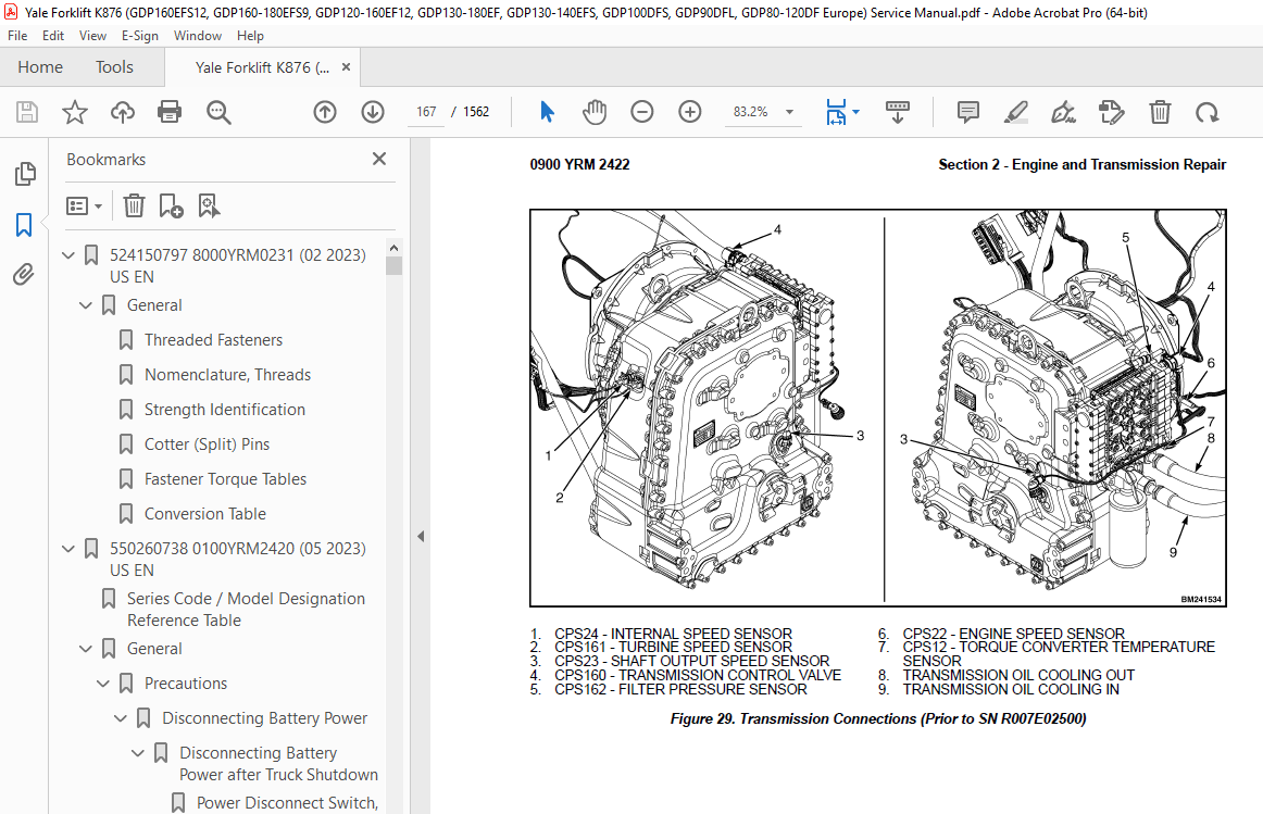
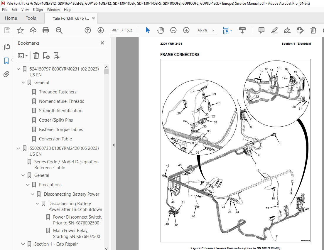
TABLE OF CONTENTS:
Yale Forklift K876 (GDP160EFS12, GDP160-180EFS9, GDP120-160EF12, GDP130-180EF, GDP130-140EFS, GDP100DFS, GDP90DFL, GDP80-120DF Europe) Service Manual – PDF DOWNLOAD
524150797 8000YRM0231 (02 2023) US EN 1
General 7
Threaded Fasteners 7
Nomenclature, Threads 7
Strength Identification 8
Cotter (Split) Pins 9
Fastener Torque Tables 14
Conversion Table 16
550260738 0100YRM2420 (05 2023) US EN 23
Series Code / Model Designation Reference Table 31
General 31
Precautions 31
Disconnecting Battery Power 31
Disconnecting Battery Power after Truck Shutdown 31
Power Disconnect Switch, Prior to SN K876E02500 31
Main Power Relay, Starting SN K876E02500 32
Section 1 – Cab Repair 34
Operator’s Cab Assembly 34
Tilting the Cab 34
Raising 34
Lowering 35
Remove Cab 36
Install 38
Cab Tilt System 40
Hand Tilt Pump 40
Remove 40
Install 41
Electric Tilt Pump 41
Remove 41
Install 42
Cab Tilt Cylinder 43
Remove 43
Install 44
Latch 44
Remove 44
Install 44
Cab Windows 44
Window Replacement 44
Front Window 45
Remove 45
Install 45
Rear Window 45
Remove 45
Install 45
Top Window 46
Remove 46
Install 46
Door Window 46
Remove 46
Install 46
Sliding Window and Sliding Tracks 46
Remove 46
Install 47
Weather Strip Replacement 47
Window Stopper Replacement 47
Sliding Window Frame 48
Remove 48
Install 48
Window Wipers 48
Window Wiper Assembly Replacement 48
Remove 48
Install 49
Front Window Wiper Motor Assembly 49
Remove 49
Install 49
Rear Window Wiper Motor Assembly 50
Remove 50
Install 50
Top Window Wiper Motor Assembly 50
Remove 50
Install 50
Window Washer System 51
Window Washer Reservoir and Pumps 51
Remove 51
Install 51
Window Washer Hoses 52
Remove 52
Install 52
Window Washer Spray Nozzles 52
Front Window 52
Remove 52
Install 53
Rear Window 53
Remove 53
Install 53
Top Window 53
Remove 53
Install 53
Cab Door Assembly 53
Cab Door 53
Remove 53
Install 54
Door Hinge 54
Greasing 54
Remove/Install 54
Door Latch 55
Remove 55
Install 56
Door Handle 56
Remove 56
Install 56
Door Release 57
Remove 57
Install 57
Door Push Button 57
Remove 57
Adjustment 57
Install 58
Steering Wheel and Steering Column Assembly 58
Steering Wheel and Horn 58
Remove 58
Install 59
Steering Column Assembly 60
Remove 60
Install 61
Shift Lever 62
Remove 62
Install 62
Gear Selection Lever 62
Remove 62
Install 62
Turn Signal Lever 62
Remove 62
Install 62
Pedals 63
Brake and Inching Pedal 63
Remove 63
Install 63
Accelerator Pedal and Sensor 63
Remove 63
Install 64
Adjust Sensor 64
Power Assist Armrest 64
Armrest Components 66
Electrical Mini-Levers 66
Remove 66
Install 67
Armrest Switch Groups 67
Remove 67
Install 68
Ignition Key Switch and Start/Stop Button Switch 68
Remove 68
Install 69
Joystick 69
Remove 69
Install 70
USB Power Socket 70
Remove 70
Install 71
12V Power Socket 71
Remove 71
Install 71
Display Replacement 71
Seat Assembly 72
Remove 72
Install 72
Initialize New Seat 73
Cab Interior 73
Floor Mat 73
Remove 73
Install 74
Radio Console 74
Remove 74
Install 75
Air Duct Replacement 75
Remove 75
Install 76
Accessories 76
Mirror Replacement 76
Sunshade Replacement 76
Top 76
Rear 76
Map Light Replacement 77
Interior Fan Replacement 77
Training Seat 77
Field Installation 77
Remove 77
Checks and Adjustments 77
Label Check and Replacement 77
Cab Tilt System Oil Level Check 78
Door Striker Pin Adjustment 78
Section 2 – Cab Heater and Air Conditioner 80
Heater/Air Conditioner Assembly 80
Access 80
Remove 81
Install 83
Heater Parts 84
Heater Core 84
Remove 84
Install 85
Water Valve 85
Remove 85
Install 86
Heater/Air Conditioning Assembly 86
Remove 86
Install 87
Filtration 88
Fresh Air Filter 88
Remove 88
Install 88
Air Conditioning Technical Detail 90
Maintenance, Service and Repairs 91
Safety Precautions 91
General Statements for Maintenance and Repairs 91
Residual Pressure 91
Refrigeration Circuit 92
Cooling Water Circuit 92
Maintenance Intervals 92
Repairs 93
Checklist 93
550260739 0700YRM2421 (05 2023) US EN 95
Series Code / Model Designation Reference Table 101
General 101
Precautions 103
Section 1 – Cooling System 104
Cooling Core Assembly 104
Section 2 – Cooling System Components 113
Cooling Fan 113
Section 2 – Checks and Adjustments 115
Cooling System Checks 115
550260740 0900YRM2422 (07 2023) US EN 125
Series Code / Model Designation Reference Table 135
General 135
Precautions 135
Disconnecting Battery Power 135
Disconnecting Battery Power after Truck Shutdown 135
Power Disconnect Switch, Prior to SN K876E02500 135
Main Power Relay, Starting SN K876E02500 136
Special Tools 138
Section 1 – Drive Shaft Repair 144
Drive Shaft Assembly 144
Section 2 – Engine and Transmission Repair 147
Engine and Transmission Assembly 147
Remove 147
Precautions Before Removal 147
Drain the Engine Cooling System 147
Remove Air Conditioning Compressor and Cab Heater Hoses 147
Tilt the Cab 149
Disconnect Batteries 149
Drain Hydraulic Oil and Remove Hydraulic Pumps 150
Drain Transmission Oil 150
Disconnect Tubes, Pipes, Cables, Wires, and Lines 150
Remove Drive Shaft 160
Remove Engine and Transmission 160
Install 162
Install Engine and Transmission 162
Install Drive Shaft 163
Connect Tubes, Pipes, Cables, Wires, and Lines 163
Connect Hydraulic and Transmission Hoses 163
Connect Batteries 163
Lower the Cab 163
Install Air Conditioning Compressor and Cab Heater Hoses 164
Refill the Systems 164
Starting the Engine 165
Engine Repair 165
Transmission Assembly 166
Remove 166
Install 170
Transmission Components 172
Transmission Clean and Inspect 215
Assemble Transmission 216
Clutch K1, First Speed 216
Input Shaft 221
Clutch KV, Forward 222
Clutch KR, Reverse 227
Clutch K2, Second Speed 232
Clutch K3, Third Speed 238
Oil Pump 242
Transmission Case 243
Transmission Oil Filter 249
Remove 249
Clean 250
Inspect 250
Transmission Control Valve 252
Remove 252
Clean 256
Inspect 256
Transmission Test and Calibration 262
Precautions 262
Transmission Oil Sampling 262
Preparation 262
Sampling Procedure 262
Stall Test 262
Stall Test Procedure 262
Inch Pedal Calibration 263
Brake and Inch Pedal Calibration 263
Clutch Calibration 264
Section 3 – Engine Intake and Exhaust Repair 265
Air Filter and Precleaner 265
Remove 265
Install 266
Exhaust System 266
Exhaust System (Cummins Tier 3/Stage IIIA) 266
Remove 266
Install 267
Exhaust System (Cummins Tier 4F/Stage IV) 267
Remove Exhaust Pipes 267
Install Exhaust Pipes 269
Exhaust After Treatment Assembly 270
Remove 270
Install 270
Exhaust After Treatment Components 271
Exhaust Seal Rings 272
Selective Catalytic Reducer (SCR) 272
Remove 272
Install 272
Decomposition Reactor Tube (DRT) 273
Remove 273
Install 273
Diesel Oxidation Catalyst (DOC) 274
Remove 274
Install 274
Exhaust System (Mercedes-Benz Stage V) 275
Remove Exhaust Pipes 275
Install Exhaust Pipes 277
Exhaust After Treatment Unit (EATU) 277
Remove 277
Install 278
Diesel Particulate Filter 278
DEF System 279
DEF System Components 279
DEF Tank 280
Remove 280
Install 281
DEF Tank Fill Cap 282
DEF Multifunctional Head 282
Remove 282
Install 282
DEF Tank Suction Filter 282
DEF Pump Assembly 282
Remove 282
Install 283
DEF Pump Filter 283
Replace (Cummins Tier 4F/Stage IV) 283
Replace (Mercedes-Benz Stage V) 284
DEF Dosing Valve (Cummins Tier 4F/Stage IV) 285
Remove 285
Install 286
DEF Dosing Valve (Mercedes-Benz Stage V) 286
Remove 286
Install 287
Fuel Tank 288
Remove 288
Clean and Repair 290
Install 290
Section 4 – Drive Axle Repair 292
Drive Axle Assembly 292
Preparation for Removal 292
Remove 293
Install 294
Planetary Gear Assembly 295
Repairing and Replacing Parts 300
Welding 300
Clean 300
Ground or Polished Parts 300
Parts With Rough Finishes 301
Axle Assemblies 301
Drying Cleaned Parts 301
Preventing Corrosion 301
Inspect 301
Service Brake Assembly 307
Clean 314
Ground and Polished Parts 314
Parts With Rough Finish 314
Service Brake and Axle Assembly 315
Inspect 315
Face Seals 315
Disc 315
Replace Parts 315
Wear Limits 316
Differential Assembly 324
Remove 324
Disassemble 329
Clean and Inspect 332
Assemble 333
Pinion Bearings Preload Adjustment 335
Press Method 335
Flange Method 336
Install Triple-Lip Oil Seal 337
Pinion Carrier Shim Set Thickness Adjustment (Depth of Pinion) 339
Main Differential and Ring Gear Assembly 341
Differential Gears Rotating Torque 343
Differential and Ring Gear Assembly 344
Differential Bearings Preload Adjustment 345
Method 1 345
Method 2 347
Ring Gear, Run Out Check 348
Ring Gear Backlash Adjustment 348
Tooth Contact Pattern Check 350
Thrust Screw Installation and Adjustment 353
Install 353
Parking Brake 355
Parking Brake Caliper 355
Remove 355
Disassemble 355
Clean and Inspect 357
Assemble 357
Install 358
Parking Brake Caliper Pads 358
Remove 358
Install 358
Drive Axle Checks and Adjustments 358
Oil Drain and Refill Procedures 358
Differential 358
Drain 358
Fill 359
Hub Assembly 359
Drain 359
Fill 359
Hydraulic System Air Removal 360
Service Brake De-Aeration 360
Parking Brake De-Aeration 360
Parking Brake Pads Adjustment 361
Inspect Wet Disk Brake Lining 362
Drive Axle Torque Specifications 363
Section 5 – Steering Axle Repair 365
Steering Axle Assembly 365
Preparation for Removal 365
Remove 365
Install 366
Tie Rod 367
Remove 367
Clean and Inspect 368
Install 368
Steering Cylinder 368
Remove 368
Disassemble 370
Clean and Inspect 372
Assemble 372
Install 373
Wheel Hubs 373
Remove and Disassemble 373
Clean and Inspect 375
Assemble and Install 375
Spindle 376
Remove and Disassemble 376
Clean 377
Assemble and Install 378
Steering Axle Checks and Adjustments 378
Maximum Steering Angle Adjustment 378
Torque Specifications 380
550260741 1900YRM2423 (05 2023) US EN 383
Series Code / Model Designation Reference Table 393
General 393
Precautions 393
Disconnecting Battery Power 393
Disconnecting Battery Power after Truck Shutdown 393
Power Disconnect Switch, Prior to SN K876E02500 393
Main Power Relay, Starting SN K876E02500 394
Section 1 – Hydraulic System Repair 396
Main Control Valve 396
Priority Valve (A) 403
Remove 403
Clean 403
Inspect 403
Component Functionality Test 403
Install 404
Check Valve (K) 404
Check Valve (I) 404
Check Valve (Q) 404
Screen Cartridge (O) 405
Disassemble 405
Component Functionality Test 405
Assemble 405
Shuttle Valves (L) and (M) 405
Remove 405
Clean 405
Inspect 406
Component Functionality Test 406
Install 406
Logic Valve (N) 406
Full Flow Relief Valve (C) (Relief Spool) 407
Remove 407
Clean 407
Inspect 407
Assemble 407
Install 407
Pilot Supply Valve (F) 407
Remove 407
Clean 407
Inspect 407
Assemble 407
Component Functionality Test 408
Install 408
Load Sense (LS) Relief Valve (H) and Full Flow Relief Valve (G) 408
Remove 408
Clean 408
Inspect 408
Component Functionality Test 408
Install 408
Load Sense Relief Valve (H) Adjustment 408
Full Flow Relief Valve (G) Adjustment 408
Load Sense Selector Valve (D) 409
Remove 409
Clean 409
Inspect 409
Assemble 409
Install 409
Lift Pressure Selector Valve (B) 409
Remove 409
Clean 409
Inspect 410
Assemble 410
Install 410
Fan Drive Section 410
Disassemble 410
Clean 410
Inspect 411
Assemble 411
Variable Displacement Pump (Primary and Secondary) 411
Remove 411
Clean 412
Inspect 412
Install 412
Electrical Actuation Module 414
Remove 414
Clean 414
Inspect 414
Assemble 414
Install 414
Emergency Lowering Valve (Lift Slice Only) 415
Remove 415
Clean 416
Inspect 416
Install 416
Load Sense and Pressure Controller Valve on Pump 416
Remove 416
Clean 416
Inspect 416
Assemble 416
Install 416
Carriage Valve 417
Carriage Valve 417
Remove 8-16T 417
Remove 16-18T 418
Clean and Inspect 419
Install 8-16T 419
Install 16-18T 421
Manual End Cap 422
Remove 422
Clean 423
Inspect 423
Assemble 423
Install 423
Tilt Lock Valve 423
Remove 423
Clean 425
Inspect 425
Assemble 425
Install 425
Lowering Control Valve 426
Remove 426
Clean 426
Inspect 426
Install 426
Hydraulic Tank 427
Remove 427
Inspect 428
Clean 428
Steam Cleaning Method 429
Chemical Solution Cleaning Method 429
Repair 429
Small Leaks 429
Large Leaks 429
Inspection after Repair 430
Install 430
Hydraulic Checks and Adjustments 431
Adjustment of Pressure Controller on Pump 431
Adjustment of Load Sense Controller on the Secondary Variable Pump 432
Adjustment of Load Sense Controller on the Primary Variable Pump 433
Hydraulic System Torque Specifications 435
Section 2 – Steering System Repair 436
Steering Control Unit 436
Remove 436
Install 437
Steering Cylinder 437
Remove 437
Disassemble 439
Clean and Inspect 441
Assemble 441
Install 442
Steering System Torque Specifications 442
Steering Control Unit 442
Steering Cylinder 442
Section 3 – Brake System Hydraulics Repair 443
Brake Treadle Valve 443
Remove 443
Install 444
Accumulator 444
Remove 444
Install 445
Pre-Charge Filling 445
Parking Brake 447
Parking Brake Caliper 447
Remove 447
Disassemble 448
Clean and Inspect 448
Assemble 448
Install 449
Parking Brake Caliper Pads 449
Remove 449
Install 450
Parking Brake Bleed 450
Parking Brake Emergency Release 451
Brake Flow Distribution Manifold 451
Remove 451
Disassemble 452
Clean and Inspect 452
Assemble 452
Install 453
Brake Control Manifold 453
Remove 453
Install 454
Orifices (F) and (G) 454
Disassemble 454
Assemble 454
Orifice (H) 454
Disassemble 454
Assemble 455
Unloading Valve (B) 455
Disassemble 455
Assemble 455
Screen 455
Disassemble 455
Assemble 455
Check Valve (E) 455
Disassemble 455
Assemble 455
Pressure Reducer Valve (C) 456
Disassemble 456
Assemble 456
Park Brake Selector Valve (A) 456
Disassemble 456
Assemble 456
Brake System Checks and Adjustments 457
Hydraulic Pressure Checks Preparation 457
Park Brake Selector Valve Check 457
Park Brake Selector Valve Coil Check 457
Accumulator Pre-Charge Check 458
Parking Brake Adjustment 458
Condition Check, Shuttle Valve (L) in the Main Control Valve 459
Condition Check, Shuttle Valve (N) in the Main Control Valve 459
Condition Check, Priority Valve on the Main Control Valve 459
Pressure Check, Port MLS1 460
Hydraulic Brake Torque Specifications 460
Hydraulic Hose Torque Procedure 461
Section 4 – Cylinder Repair 462
Side Shift Cylinder 462
Disassemble 462
Clean and Inspect 462
Assemble 463
Fork Positioner Cylinder 463
Disassemble 463
Clean and Inspect 464
Assemble 464
Tilt Cylinders 464
Disassemble 464
Clean and Inspect 465
Assemble 465
De-Aeration of the Tilt Cylinders before Start-up 466
Lift Cylinders 467
Disassemble 467
Clean and Inspect 468
Assemble 468
550260742 2200YRM2424 (05 2023) US EN 471
Series Code / Model Designation Reference Table 477
General 477
Disconnecting Battery Power 477
Disconnecting Battery Power after Truck Shutdown 477
Power Disconnect Switch, Prior to SN K876E02500 477
Main Power Relay, Starting SN K876E02500 478
Section 1 – Electrical 480
General Fault Finding 480
Preparation 480
Define the Problem Area 480
Identify Possible Causes of Malfunction 480
Determine the Most Probable Cause 480
Fuse Check 480
Wiring Check 480
Component Check 480
Repair and Test 481
Harnesses and Connectors 481
Harnesses Overview 481
Harness Connectors and Terminals 486
Frame Connectors 486
Frame Connectors (Starting SN R007E03500) 489
Powertrain Connectors (Tier 3/Stage IIIA) 492
Powertrain Connectors (Tier 4F/Stage IV – QSB4 5) 494
Powertrain Connectors (Tier 4F/Stage IV – QSB6 7) 496
Powertrain Connectors (Stage V) (Prior to SN R007E03500) 498
Powertrain Connectors (Stage V) (Starting SN R007E03500) 500
Cab Connectors 502
EATU Connectors (Tier 4F/Stage IV) 519
EATU Connectors (Stage V) 520
DEF Connectors (Tier 4F/Stage IV) 522
DEF Connectors (Stage V) 522
Lights Connectors 523
Hoodspine Connectors (Tier 3/Stage IIIA) 527
Hoodspine Connectors (Tier 4F/Stage IV – QSB4 5) 528
Hoodspine Connectors (Tier 4F/Stage IV – QSB6 7) 529
Hoodspine Connectors (Stage V) 530
Mast Connectors 531
Carriage Connectors 533
2-Stage Mast 533
3-Stage Mast 534
Automatic Greasing Connectors 535
Fuses and Relays 537
CANbus Circuit 543
Greasing System Electrical 548
Section 2 – Controls 549
User Interface Display 549
General 549
User Interface Display Overview 550
Fault Codes 550
Transmission Calibration 550
Section 3 – User Interface Display 551
Navigation Key 551
Startup Sequence 552
Home Screen 553
Direction and Gear Range Indicator 554
Screen Brightness Menu 555
HVAC Controls Menu 556
Logging in 558
Log In/Out 558
View the Hardware and Software Versions 558
View the Fault Log 559
Fault Log 559
Calibrations 560
Calibrate the Clutch Pack 560
Calibrate the Brake Pedal 561
Calibrate the Accelerator Pedal 561
Diagnostics Menu 562
Hydraulics 562
1st Hyd Function 563
2nd Hyd Function 563
Aux Hyd Functions 563
Drive 564
Engine 564
Transmission 564
Controllers 564
VSM 564
Hydraulic Controller 1 564
Armrest Module 564
High Current Module 565
Light module 565
Overview 565
Temperatures 565
Speed Limiters 566
Hydraulic Limits 566
Settings 566
Hydraulics 566
Operators 567
Maintenance 567
Truck Setup 567
Display 568
Lights 568
Switches 568
Display Flow Chart 569
550260743 2400YRM2425 (05 2023) US EN 601
Series Code / Model Designation Reference Table 607
General 607
Disconnecting Battery Power 607
Disconnecting Battery Power after Truck Shutdown 607
Power Disconnect Switch, Prior to SN K876E02500 607
Main Power Relay, Starting SN K876E02500 608
Greasing System 610
Grease Pump Assembly 610
Greasing System Components 612
Grease Line Identification 612
Grease Reservoir 617
Refilling the Grease Reservoir 618
Test Cycles Using the Button on the Pump 619
Bleeding the Pump 619
Bleeding the System 620
Checks and Adjustments 635
Checks and Adjustments 635
Test Procedures 635
Check pressure switch (valve) and cable 635
Check pump and 5/2-way valve 635
Check for Internal System Leaks 636
Technical Data 637
Technical Data 637
Pump Unit 637
Grease Recommendations 637
Electrical 637
Torque Specifications 639
550260744 4000YRM2426 (05 2023) US EN 641
Series Code / Model Designation Reference Table 651
General 651
Safety Procedures 654
When Working Near The Mast Always 654
When Working on the Hydraulic System 654
Section 1 – Forks and Carriage Repair 655
Forks 655
Fork Guide And Fork Pin 8-16T 666
Fork Hanger 667
Carriage Assembly 670
Carriage Components 680
Section 2 – Mast Repair 694
Mast Assembly 694
Mast Components 712
Mast Checks and Adjustments 743
Torque Specifications 758
Torque Values 758
Torque Values for Container Attachment 8-16T 758
Torque Values for Mast and Carriage 8-16T 758
Torque Values for Mast and Carriage 16-18T 758
Tightening Torques 760
550260745 8000YRM2427 (05 2023) US EN 765
Series Code / Model Designation Reference Table 771
General 771
Weight and Dimensions 774
Loading Procedures 792
Loading A Truck on a Transport 792
Preparing Truck for Loading on a Trailer with Mast Installed 792
Loading Disassembled Components 793
Unloading Procedures 799
Unloading A Truck From Transport 799
Unloading Disassembled Components 800
Removal of Forks Attached to a Basic Truck 800
Removal of Forks Attached to the Carriage 801
Moving and Towing 803
Releasing the Parking Brake 803
Moving a Disabled Lift Truck 803
Safety Precautions When Working Near The Mast 805
When Working Near The Mast Always 805
Before Starting Repairs To The Hydraulic System Always 806
Truck Assembly 807
Mast Assembly 807
Installing Hose Sheaves on the 2-Stage Mast 807
Preparations 808
Installing the Mast 809
Installing the Tilt Cylinders 812
Adjusting the Tilt Cylinders 813
Connecting the Lift Cylinder Supply Hoses 815
Connecting the Mast Header Hoses 815
Removing the Carriage Transport Lock [GDP80-160 (GDP190-360)] 816
Carriage 817
Install Carriage 817
Connecting Hoses and Electrical Cable 819
Forks 821
Install Forks 821
Pin Type Forks 821
Without Fork Positioning 821
With Fork Positioning 823
Hook Type Forks 826
Integrated Forks [GDP160-180 (GDP360-400) Only] 827
Adjustments 828
Lift Chain and Fork Height Adjustment 828
Header Hose and Cable Tension Adjustment 832
Cab Lights 834
Install Cab Lights 834
Labels 835
Attach Mast Labels 835
Lubricate 836
Lubrication Points 836
Automatic Greasing System (Optional) 837
General Checks After Assembly 839
Plumbing Check 839
Lubrication Check 839
Fluid Level Check 839
Functionality Check 839
Literature Package Check 839
Cleaning 839
Labels 839
Wheels and Tires 840
Remove Wheels From Lift Truck 840
Remove Pneumatic Tire From Wheel 841
Remove Solid Rubber Tire from Wheel 844
Install Pneumatic Tire on Wheel 845
Install Solid Rubber Tire on Wheel 848
Adding Air Pressure to Tires 849
Install Wheels on Lift Truck 850
Pre-Delivery 851
Perform Pre-Delivery Inspection 851
Delivery 852
Instructions Operating Manual 852
Instructions Daily Maintenance 852
Handing Over Truck 852
550260746 8000YRM2429 (05 2023) US EN 855
Series Code / Model Designation Reference Table 861
General 861
Precautions 861
Disconnecting Battery Power 861
Disconnecting Battery Power after Truck Shutdown 861
Power Disconnect Switch, Prior to SN K876E02500 861
Main Power Relay, Starting SN K876E02500 862
Main Components 864
Hood Assembly 864
Running Boards, Steps and Mud Flaps 866
Counterweight 868
Label Replacement 871
550260747 8000YRM2430 (05 2023) US EN 873
Series Code / Model Designation Reference Table 879
Counterweights 879
Lift Truck Weights 880
Mast Speeds 881
Tire Sizes 889
Hydraulic System 891
Electrical System 893
Engine Specifications 894
Capacities 895
Torque Specifications 897
Transmission ZF 897
Isolator Mounting 897
Isolator Nut 897
Transmission Bracket to Transmission 897
Flywheel Housing Mounting Capscrews 897
Flexplate to Flywheel Capscrews 897
Dipstick Mounting Capscrews 897
Driveline and Axle 897
Universal Joint Capscrews 897
Axle to Frame Capscrews 897
Counterweight Torque 897
Counterweight (without Lifting Eyes) 897
Top Capscrews (3) 897
Rear Capscrews (2) 897
Counterweight (with Lifting Eyes) 897
Top Special Bolt (2) – Forward 897
Top Capscrew (1) – Rearward 897
Rear Capscrews (2) 897
Differential 897
Brakes 897
Steering 897
Steering Wheel Nut 897
Steering Valve Mounting Capscrews 897
Steer Cylinder Mounting Capscrews 897
Tie Rod Locknuts 897
Wheel Nuts 897
Drive Wheels 897
Steer Wheels 898
Hydraulic System 898
Mast 898
Mast Mounting Pin Plate to Frame 898
Wear Plate Nuts 898
Bearing Block Capscrews 898
Bearing Block Bracket Capscrews 898
Carriage 898
Bearing Block Capscrews 898
Bearing Block Bracket Capscrews 898
Sideshift Cylinder Rod Locknut (1 UNF) 898
Tilt Cylinders 899
Anchor Pin Capscrews 899
Rod End Lock Nuts (M12x1 75) 899
Cummins Diesel, Lubrication System 899
550260748 8000YRM2431 (05 2023) US EN 901
Series Code / Model Designation Reference Table 909
General 909
Serial Number Data 909
Disconnecting Battery Power 910
Disconnecting Battery Power after Truck Shutdown 910
Power Disconnect Switch, Prior to SN K876E02500 910
Main Power Relay, Starting SN K876E02500 911
Section 1 – Truck Handling Procedures 912
Moving and Towing a Lift Truck 912
Putting a Lift Truck on Blocks 913
Cleaning a Lift Truck 914
Section 2 – Safety Procedures Before Starting Maintenance 916
Precautions 916
Making Checks From the Driver Seat with Engine Running 916
Section 3 – Periodic Maintenance Schedule 917
Periodic Maintenance Schedule 917
Daily Inspection 918
Daily Condition Checks 918
Daily Fluid Level Checks 919
Daily Checks from the Driver Seat with Engine Running 920
Initial Inspection 921
First Inspection after First 100 Hours of Operation 921
Periodic Maintenance 922
Inspect and Adjust 922
Lubricate 926
Change 928
Change Every 24 Months 930
Change Every 3 Years 930
Periodic Maintenance Schedule – ELME 580 Series Container Attachment 931
Periodic Maintenance 931
Inspect and Adjust 931
Lubricate 932
Change 932
Section 4 – Periodic Maintenance Procedures 933
Air Conditioning System 933
Attachment 933
Automatic Greasing System (Optional) 933
Brake Cooling Filter 934
Brake System Accumulator 934
Cab Air Filter 935
Cab Door Hinges 935
Chain Sheave Bearings (18T Front End) 935
Controls, Levers, Switches and Pedals 936
Cooling System 936
Crankcase Breather Element (Cummins Tier 4F/Stage IV Only) 937
Diesel Exhaust Fluid (DEF) System 938
DEF Pump Filter (Cummins Tier 4F/Stage IV) 938
DEF Pump Filter (Mercedes-Benz Stage V) 938
DEF Tank Fill Cap 940
DEF Tank Suction Filter (Cummins Tier 4F/Stage IV and Mercedes-Benz Stage V) 940
Diesel Particulate Filter (Mercedes-Benz Stage V Only) 941
Drive Axle, Differential and Axle Hub Assembly 945
Check Oil Level 945
Change Oil 945
Drive Wheel Hub Bearing Preload 945
Drive Shaft 945
End Beam Slider Pads 945
Engine Air Filter 946
Engine Air Intake Piping and Charge Air Hoses 946
Engine and Transmission Mounts 947
Engine Compartment 948
Engine Drive Belt (Cummins Tier 3/Stage IIIA,Tier 4F/Stage IV) 948
Engine Drive Belt Tensioner and Pulleys 948
Bearing Condition (Cummins Tier 3/Stage IIIA,Tier 4F/Stage IV) 948
Pulley Alignment (Cummins Tier 3/Stage IIIA,Tier 4F/Stage IV) 949
Tensioner Condition (Cummins Tier 3/Stage IIIA,Tier 4F/Stage IV) 949
Engine Drive Belt Tensioner and Pulleys (Mercedes-Benz Stage V) 950
Engine Oil 951
Engine Oil Level 951
Engine Oil and Engine Oil Filter 954
Engine Valve Adjustment (Cummins Tier 3/IIIA and Tier 4F/Stage IV Only) 955
Remove Cover 956
Adjust 958
Clean and Inspect 959
Test 959
Continuity Check 959
Short Circuit from Pin to Pin Check 960
Install Cover 960
Engine Valve Adjustment (Mercedes-Benz Stage V) 961
Every 2,000 Hours 961
Remove Cover 961
Adjust 962
Install Cover 964
Exhaust After Treatment Unit Compartment (Cummins Tier 4F/Stage IV and Mercedes-Benz Stage V only) 964
Exhaust System 964
Extension Beam Wear Pads 964
Fault Codes 965
Forks 965
Fork Guide Bearing Blocks 966
Fork Guide Wear Pads 967
Fork Pins, Carriage Pins, and Carriage Sliding Surfaces 967
Frame, Mast, Carriage and Attachment 967
Fuel, DEF, Oil, Coolant, and Hydraulic System 968
Fuel/Water Separator and Final Fuel Filter 968
Fuel Tank Breather 969
Header Hose Assembly 970
Horn, Gauges, Lights, Alarms and Control System 970
Hydraulic Fan Motor 970
Every 2,000 Hours 970
Hydraulic System Oil 970
Hydraulic Tank Breather 972
Hydraulic Tank Return Filter 973
Inching Pedal Sensor Calibration 973
Lift Chains 973
Check and Lubricate Lift Chains 973
Adjust Lift Chains 974
Inspect Lift Chains 975
Chain Elongation 975
Lift Chain Wear and Damage 976
Lift System Accumulator (Optional) 977
Load Rollers 977
Lumber Forks 977
Mast, Carriage, and Attachment 977
Mast Bearing Blocks 978
Mast Channels 978
Mast Pivot Pins 978
Operator Presence System 978
Operator Restraint System 979
Parking and Service Brakes 979
Radiator Assembly 980
Side Shift Cylinder Bearings 980
Side Shift Slider Pads 980
Side Shift Wear Pads 980
Signals from the Spreader Control System 980
Steering Axle Grease Fittings 980
Steering System 981
Steer Wheel Hubs 981
Steering Wheel Hub Bearings 981
Tilt Cylinder Pivot Pins 984
Transmission 985
Turbo Charger (Cummins Engines Only) 987
Twist Locks (Container Locking Mechanism) 988
Inspect 988
Lubricate 988
Replace 989
Vibration Damper (Viscous, Cummins Tier 3/Stage IIIA and Tier 4F/Stage IV Only) 989
Warning and Safety Labels 989
Wear Pads Carriage 990
Every 500 Hours 990
Wheels and Tires 990
Wheels, Tires, and Tire Pressure 990
Tire Pressure Monitoring System (TPMS) 991
Sensor Replacement 993
Remove Wheels from Lift Truck 994
Adding Air Pressure to Pneumatic Tires 999
Install Wheels on Lift Truck 1004
Windows and Mirrors 1004
Windshield Washer Fluid Level 1004
Section 5 – Capacities and Specifications 1005
Approved Fuel and Engine Oil 1005
Approved Oils, Fluids, and Grease 1005
Engine Oil Viscosity 1007
Electrical Components 1007
550260749 8000YRM2432 (08 2023) US EN 1019
Series Code / Model Designation Reference Table 1025
Electrical Circuit Cross Reference 1025
Electrical Schematics (Prior to SN R007E02500) 1027
Electrical Schematics – NCEA Cabin (Starting SN R007E02500) 1058
Electrical Schematics – Tier 3/Stage IIIA 6 7L (Starting SN R007E02500) 1070
Electrical Schematics – Tier 4F/Stage IV 4 5L (Starting SN R007E02500) 1084
Electrical Schematics – Tier 4F/Stage IV 6 7L (Starting SN R007E02500) 1098
Hydraulic Schematics 1112
550260750 9000YRM2433 (09 2023) US EN 1119
Series Code / Model Designation Reference Table 1125
General 1125
Section 1 – Troubleshooting 1126
Troubleshooting – Symptom Based 1126
Mast 1126
Troubleshooting Procedures 1126
Cab Heater and Air Conditioning 1127
Preliminary Checks 1127
Checking System Air Output 1127
Check The Sight Glass for Bubbles 1127
Troubleshooting Procedures 1128
General System 1128
Climate Control Display Diagnostics Menu Errors 1130
Cooling System 1131
Troubleshooting Procedures 1131
Steering Axle 1133
Troubleshooting Procedures 1133
Hydraulic System 1134
Troubleshooting Procedures 1134
Parking Brake 1134
Troubleshooting Procedures 1135
Service Brake 1136
Troubleshooting Procedures 1136
Steering System 1137
Troubleshooting Procedures 1137
Transmission 1138
Troubleshooting Procedures 1138
Section 2 – Error Codes 1140
ABS 1140
Air Compressor 1146
Armrest 1147
Cabin Tip 1156
Cabin Tip L 1157
Cabin Tip R 1158
Communications 1159
DC/DC Converter 1161
Display 1163
Display 2 1163
Display Camera 1164
DNR 1164
Engine (Cummins) 1165
Cummins Engine 1165
General 1165
Fault Code Descriptions 1165
Finding Fault Code Information 1165
Electronic Throttle Calibration 1166
Stationary Regeneration Procedure 1166
Engine (Mercedes-Benz) 1210
General 1210
Finding Fault Code Information 1210
ACM Faults 1210
CPC4 Faults 1232
MCM Faults 1260
Greasing (Frame) 1300
Greasing (Spreader) 1302
Heating Ventilation and Air Conditioning (HVAC) 1303
Hydraulic Controller 1306
Hydraulic Controller 1 1306
Hydraulic Controller 2 1307
Hydraulic Controller 3 1308
Other 1308
RAM Revolver 1309
Spreader 1310
Spreader (Innovation) 1322
Telemetry 1397
TPMS 1397
Transmission (ZF) (Prior to SN: K876E02500X) 1398
Transmission (ZF) (Starting SN: K876E02500X) 1438
VSM 1519
More products