$41.95
Yale G876 (GDP190DC, GDP210DC, GDP230DC, GDP230DCS, GDP250DC, GDP280DC) Service Manual PDF
Yale Forklift G876 (GDP190DC, GDP210DC, GDP230DC, GDP230DCS, GDP250DC, GDP280DC) Service Manual – PDF DOWNLOAD
FILE DETAILS:
Yale Forklift G876 (GDP190DC, GDP210DC, GDP230DC, GDP230DCS, GDP250DC, GDP280DC) Service Manual – PDF DOWNLOAD
Language : English
Pages : 1114
Downloadable : Yes
File Type : PDF
IMAGES PREVIEW OF THE MANUAL:
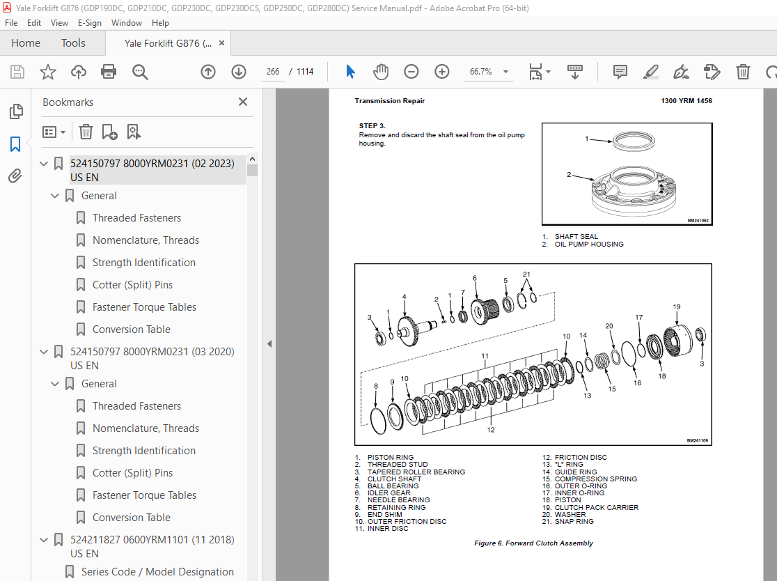

TABLE OF CONTENTS:
Yale Forklift G876 (GDP190DC, GDP210DC, GDP230DC, GDP230DCS, GDP250DC, GDP280DC) Service Manual – PDF DOWNLOAD
524150797 8000YRM0231 (02 2023) US EN 1
General 7
Threaded Fasteners 7
Nomenclature, Threads 7
Strength Identification 8
Cotter (Split) Pins 9
Fastener Torque Tables 14
Conversion Table 16
524150797 8000YRM0231 (03 2020) US EN 23
General 27
Threaded Fasteners 27
Nomenclature, Threads 27
Strength Identification 28
Cotter (Split) Pins 29
Fastener Torque Tables 34
Conversion Table 36
524211827 0600YRM1101 (11 2018) US EN 43
Series Code / Model Designation Reference Table 47
General 47
Fault Codes 48
Normal Mode 48
Fault Log Mode 49
Access 49
Exit 49
Clear 49
Electronic Throttle Calibration 49
Electronic Throttle Calibration Procedure 50
Stationary Regeneration Procedure 50
550033398 0100YRM1459 (12 2018) US EN 79
Series Code / Model Designation Reference Table 83
Description and Operation 83
Heater System 83
General 83
Air Conditioning 84
General 84
Dryer 85
Compressor Lubrication 86
Control Systems, Sensors, and Switches 86
Climate Control 87
Description 87
Service Menu 87
Set Up 88
View 1 and View 2 88
Error List 89
Statistics 89
Exit 89
Temperature Sensors 89
Troubleshooting 89
Water Valve 90
Troubleshooting 90
Remove and Replace 92
Standard Heater Assembly 93
Access 93
Remove 93
Install 94
Standard Heater Parts 95
Heater Core 95
Remove 95
Install 96
Blower 96
Remove 96
Install 97
Water Valve 98
Remove 98
Install 98
Push/Pull Cable 99
Water Valve Cable 99
Remove 99
Install 99
Heater/Air Conditioner Assembly 100
Remove 100
Install 101
Heater/Air Conditioner Parts 101
Vent Door 101
Remove 101
Install 102
Heater Core 102
Remove 102
Install 103
Evaporator Core 104
Remove 104
Install 105
Blower 106
Remove 106
Install 106
Thermostat 107
Remove 107
Install 108
Water Valve 108
Remove 108
Install 109
Air Conditioning Technical Detail 110
550033400 0100YRM1390 (12 2018) US EN 113
Series Code / Model Designation Reference Table 121
General 121
Description of Operation 123
Cab Structure 123
Cab Tilt System 123
Cab Tip-Up System 125
Tilting the Cab 126
Raising 126
Lowering 127
Remove and Install 128
Cab Door Assembly 128
Cab Door 128
Remove 128
Install 128
Door Hinge 129
Remove 129
Install 129
Door Latch 130
Remove 130
Install 130
Door Handle 130
Remove 130
Install 130
Door Release 131
Remove 131
Install 131
Door Push Button 131
Remove 131
Install 132
Cab Tilt System 132
Electric Tilt Pump 132
Remove 132
Install 132
Hand Tilt Pump 132
Remove 132
Install 133
Cab Tilt Cylinder 134
Remove 134
Disassemble 134
Clean 136
Inspect 136
Assemble 136
Install 137
Latch 137
Remove 137
Install 138
Brake and Inching Pedal 139
Remove 139
Install 139
Accelerator Pedal and Sensor 140
Remove 140
Install 140
Adjust Sensor 140
Seat Assembly 140
Seat 140
Remove 140
Install 141
Seat Cushion 141
Remove 141
Install 142
Back Cushion 142
Remove 142
Install 142
Seat Suspension Replacement 142
Boot Replacement 142
Power Assist Armrest 166
Release Cable 166
Remove 166
Install 166
Gas Spring 166
Remove 166
Install 167
Joystick 167
Remove 167
Install 167
Electrical Levers 167
Remove 167
Install 168
Armrest Rocker Switches 168
Remove 168
Install 168
Armrest Top Cover 168
Remove 168
Install 168
Instrument Panel 169
Key Switch 169
Remove 169
Install 169
12V Power Socket 169
Remove 169
Install 169
Electric-Operated Heat Control and Air Recirculation Control (Airco Only) 170
Remove 170
Install 170
Cable-Operated Heater Control (Heater Only) 171
Remove 171
Install 171
Air Conditioning Switch Replacement 171
Instrument Panel Rocker Switches Replacement 171
Parking Brake Switch 172
Remove 172
Install 172
Indicator Display Replacement 172
Instrument Panel Top Console 172
Remove 172
Install 173
Steering Wheel and Column Assembly 173
Steering Wheel and Horn 173
Remove 173
Install 175
Steering Column Assembly 175
Remove 175
Install 176
Adjustment Handle 176
Remove 176
Install 176
Main Warning Lights 177
Remove 177
Install 177
Shift Lever 177
Remove 177
Install 177
Turn Signal Lever 177
Remove 177
Install 177
Window Wipers 178
Window Wiper Assembly Replacement 178
Remove 178
Install 178
Window Wiper Motor Replacement 178
Front Window Wiper Motor 178
Install 178
Rear Window Wiper Motor Assembly 179
Remove 179
Install 179
Top Window Wiper Motor Assembly 179
Remove 179
Install 179
Window Washer System 180
Window Washer Reservoir and Pumps 180
Remove 180
Install 180
Window Washer Hoses 181
Hoses for Top and Rear Window 181
Install 182
Window Washer Spray Nozzles 182
Front Window 182
Remove 182
Install 182
Rear Window 183
Remove 183
Install 183
Top Window 183
Remove 183
Install 183
Window Replacement 183
Front Window 185
Remove 185
Install 185
Rear Window 185
Remove 185
Install 185
Top Window 186
Remove 186
Install 186
Door, Upper/Lower Window 187
Remove 187
Install 187
Sliding Window and Sliding Tracks 187
Remove 187
Install 189
Weather Strip Replacement 189
Window Stopper Replacement 189
Window Seal Replacement 190
Sliding Window Frame 190
Remove 190
Install 190
Floor Mat 190
Front Floor Mat 190
Remove 190
Install 191
Rear Floor Mat 191
Remove 191
Install 192
Radio Console 192
Remove 192
Install 192
Air Duct Replacement 193
Remove Front 193
Remove Rear 193
Install 194
Accessories 194
Mirror Replacement 194
Sunshade Replacement 194
Top 194
Rear 195
Map Light Replacement 195
Interior Fan Replacement 195
Training Seat 195
Field Installation 195
Remove 195
Label Replacement 196
Checks and Adjustments 196
Check Oil Level for Cab Tilt System 196
Door Striker Pin Adjustment 197
Brake Pedal Adjustment 197
Dry Brake 197
Wet Brake 198
Inching Pedal Adjustment 198
Inching Pedal Sensor Adjustment 198
Sensor Adjustment Using Dana Dashboard Software 198
Sensor Adjustment using the APC200 Display 199
Sensor Adjustment for Trucks with ZF Transmission 200
Inching Pedal Sensor Calibration 200
Sensor Calibration using Dana Dashboard Software 200
Sensor Calibration using APC200 Display 200
Sensor Calibration for Trucks with ZF Transmission 201
550035502 1300YRM1455 (11 2018) US EN 205
Series Code / Model Designation Reference Table 209
General 209
Description 209
General 209
Clutch 214
Operation 214
Hydraulic Operation 214
Clutch Valve 215
Cooling and Lubrication 216
Control System 217
Transmission Control Unit (TCU) 218
Operating Modes 218
Normal Mode 218
Substitute Clutch Control 218
Limp-Home Mode 218
Transmission Shut Down Mode 218
TCU Shut Down Mode 218
Transmission Exceed Codes 218
Self-Test 219
Fault Codes 219
Description 219
Fault Log Mode 219
Access 219
Exit 220
Clear 220
Fault Log Memory 220
Fault Rectification 220
Hydraulic Control Valve 221
Hydraulic Control Valve Repair 222
Solenoid Replacement 222
Pressure Check 222
Pressure Specifications 223
Speed and Temperature Sensors 223
Speed Sensors 224
Test 225
Temperature Sensors 225
Shift Lever 225
PedalFoot Directional Control 225
ZF Transmission Test and Calibration 226
Transmission Test and Calibration 226
Precautions 226
Stall Test 226
Description 226
Stall Test Procedure 226
Inch Pedal Calibration 227
Description 227
Calibration 227
Brake and Inch Pedal Adjustment 227
Inch Sensor Adjustment 227
Inch Pedal Calibration 228
Preparation 228
Calibration Procedure Using the Calibration Switch 228
Calibration Procedure Using the Testman software 228
Inch Pedal Calibration Fault Codes 228
Clutch Calibration 229
Description 229
Clutch Calibration Procedure 230
Manual Clutch Calibration Procedure 230
Testman Clutch Calibration Procedure 231
Testman 231
Description 231
Connection 232
Truck Configuration 232
Configuration 232
Limitations 232
Capacities and Specifications 233
Electrical Specifications 233
Transmission Control Unit Diagram 233
ZF Transmission Fault Codes 235
Transmission Exceed Codes 235
Testman Fault Codes 236
550035503 1300YRM1456 (12 2015) US EN 247
Series Code / Model Designation Reference Table 251
Special Tools List 252
Transmission Repair 253
Remove 253
Disassemble 257
Clean and Inspect 296
Housings 297
Oil Seals and Gaskets 297
Bearings 297
Gears and Shafts 297
Assemble 298
Transmission Oil Filter Assembly Replacement 345
Clean 346
Inspect 346
Install 347
Control Valve Replacement 352
Remove 352
Install 353
Control Valve Repair 354
Disassemble 354
Clean 358
Inspect 358
Assemble 359
550088524 4000YRM1647 (07 2016) US EN 367
Series Code / Model Designation Reference Table 373
General 373
Description And Operation 373
Mast System 373
Tilting 373
Lifting 374
Operation 374
Pilot Operated Check Valves 375
Gland Lubrication 376
Emergency Lowering Valve 376
Operation 376
Lift Chains 377
Elongation Through Wear 377
Speed of Wear 377
Plate Height Wear 378
Lubrication 378
Restoring The Oil Film 378
Maintenance 378
Maintaining The Presence of Oil 379
Corrosion Protection 379
Requirements for Chain Lubricant 379
Load Rollers 380
Bearing Blocks 380
Carriage 381
Standard Carriage with Manual Fork Positioning 381
Standard Carriage with Hydraulic Fork Positioning 381
Dual Function Side Shift and Fork Positioning (DFSSFP) Carriage 382
Integral Side Shift 382
Carriage Valve 383
Alternating Pressure and Tank (P & T) 383
Fixed Pressure and Tank (P & T) 383
Flow Divider for Simultaneous Fork Positioning 383
Valve for Dual Function with Side Shift and Fork Positioning (DFSSFP) 385
Fixed Pressure and Tank System (Fixed P & T) 387
Forks 389
Safety Procedures When Working Near Mast 390
Before Starting Repairs to the Hydraulic System, Always: 391
Remove and Replace 391
Forks 391
Remove 391
Install 392
Fork Guide And Fork Pin 393
Remove 393
Install 393
Carriage 394
394
Remove 394
Install 395
Carriage Bearing Blocks 396
Remove 396
Install 397
397
Carriage Load Rollers 397
Replace 397
399
Side Shift Cylinder 399
Remove 399
Disassemble 399
Clean And Inspect 400
Assemble 400
Install 401
Fork Positioner Cylinder 401
Remove 401
Disassemble 402
Clean and Inspect 402
Assemble 403
Install 403
Carriage Valves 403
Remove 403
Install 404
404
Valve for Fixed P & T Systems 404
Remove and Disassemble 404
Clean and Inspect 406
Assemble and Install 406
Flow Divider for Simultaneous Fork Positioning Valve 407
Restrictor Valve and Relief Valve Replacement 407
Dual Function Valve for Side Shifting and Fork Positioning 407
Solenoid Valve Replacement 407
Relief Valve Replacement 408
Remove 408
Install 408
Mast 408
Lift Chains and Top Chain Anchor 408
Remove 408
Install 408
Chain Anchor On Carriage 409
Remove 409
Install 409
Chain Sheave 410
Remove 410
Install 410
Header Hoses 411
Remove 411
Install 413
Electric Mast Cable 413
Remove 413
Install 413
Hose Sheave 414
Remove and Disassemble 414
Assemble and Install 414
Mast Assembly 415
Remove 415
Disassemble 417
Assemble 418
Install 419
Inner Mast Load Rollers 421
Replace 421
Mast Bearing Blocks 422
Remove 422
Install 422
Lift Cylinders 423
Remove 423
Disassemble 426
Clean and Inspect 426
Assemble 426
Install 427
Tilt Cylinders 428
Remove 428
Disassemble 429
Clean and Inspect 429
Assemble 429
Install 430
Checks and Adjustments 431
General Checks 431
Mast Condition Check 431
Mast Operation Check 432
Counterbalance Valve Check (for E876 and E877 Only) 432
Fork Inspection and Adjustment 432
Lift Chain Inspection 433
Lift Chain Lubricant Requirements 434
Lift Chain Lubrication Procedure 434
Leak Checks 434
Mast Vertical Creep 434
Mast Tilt Drift 435
Adjustments 435
Lift Cylinder Shimming 435
Lift Chain and Fork Height Adjustment 437
Header Hose Tension Adjustment 439
Electric Mast Cable Tension Adjustment 439
Counterbalance Valve Adjustment 439
Tilt Cylinder Backward Tilt Angle Adjustment 440
Mast Support Pad Adjustment 440
Troubleshooting 440
Introduction 441
No Hydraulic Movement With Engine Running 441
Initial Basic Check 441
442
Electrical Supply 442
Hydraulic Supply 442
Fault Code 442
No Lowering Possible with Engine OFF 443
Incorrect Movement 443
Irregular (shaking) Movement
or
Slight Carriage Movement When Starting Engine
443
Unequal Movement of Left And Right Tilt Cylinder 443
Insufficient Lifting Speed 443
Insufficient Lifting Capacity 444
Incorrect Lowering Speed 444
Lift Cylinder Creep 444
Tilt Cylinder Creep 444
550123389 0100YRM1900 (12 2015) US EN 447
Series Code / Model Designation Reference Table 451
General 451
Description 451
Remove and Install 452
Air Filter Assembly (Tier 3/Stage IIIA) 453
Remove 453
Install 453
Air Filter Assembly (Tier 4F/Stage IV) 454
Remove 454
Install 454
Exhaust System (Tier 3/Stage IIIA) 455
Remove 455
Install 455
Exhaust System (Tier 4F/Stage IV) 456
Exhaust Pipes High Mount 456
Remove 456
Install 456
Exhaust Pipes and Diffuser Low Mount 457
Remove 457
Install 457
Exhaust Seal Rings 457
Selective Catalytic Reducer (SCR) 458
Remove 458
Install 458
Decomposition Reactor Tube (DRT) 458
Remove 458
Install 459
Diesel Oxidation Catalyst (DOC) 459
Remove 459
Install 459
Hood Assembly 459
Remove 459
Install 461
Running Boards, Steps and Mud Flaps 461
Hydraulic Tank 462
Remove 462
Inspect 465
Clean 465
Steam Cleaning Method 465
Chemical Solution Cleaning Method 465
Repair 466
Small Leaks 466
Large Leaks 466
Inspection after Repair 466
Install 466
Fuel Tank 468
Remove 468
Clean and Repair 469
Install 469
Engine and Transmission (Tier 3/Stage IIIA) 470
Remove 470
Precautions 470
Remove Air Conditioning Compressor 471
Drain the Engine Cooling System 472
Drain Hydraulic Oil 472
Drain Transmission Oil 472
Disconnect Drive Shaft, Fan Clutch, Tubes, Pipes, Cables, Wires and Lines 473
Remove Engine and Transmission 475
Install 477
Install Engine and Transmission 477
Install Air Conditioning Compressor 477
Connect Drive Shaft, Fan, Tubes, Pipes, Cables, Wires and Lines 477
Refill the Systems 478
Starting the Engine 478
Engine and Transmission (Tier 4F/Stage IV) 479
Remove 479
Precautions 479
Remove Air Conditioning Compressor 479
Drain the Engine Cooling System 480
Drain Hydraulic Oil 481
Drain Transmission Oil 481
Disconnect Drive Shaft, Fan Clutch, Tubes, Pipes, Cables, Wires and Lines 481
Remove Engine and Transmission 483
Install 484
Install Engine and Transmission 484
Install Air Conditioning Compressor 484
Connect Drive Shaft, Fan, Tubes, Pipes, Cables, Wires and Lines 485
Refill the Systems 485
Starting the Engine 486
Operator’s Cab 486
Remove 486
Install 488
Cab Tilt System Oil Filling 489
Counterweight 490
Remove 491
Install 492
Label Replacement 492
550123390 0700YRM1929 (11 2018) US EN 495
Series Code / Model Designation Reference Table 499
General 499
Cooling System 499
Cooling System Description 499
Cooling Cores 499
Fan 500
Fan Clutch 500
Fan Clutch Engagement 500
Shroud 501
Engine Cooling System 502
Water Pump 502
Thermostat 502
Expansion Tank And Radiator Cap 503
Cab Heater 503
Coolant 504
DEF Heater 505
Charge Air Cooling System 505
Transmission Oil Cooling System 505
Hydraulic Oil Cooling System 506
Hydraulic Oil Cooling 506
Oil Filtration and Oil Cooling 507
Brake Cooling 508
Hydraulic Control System 508
Service and Repair 508
Cooling System Checks 508
Basic Checks 508
Coolant Quality Checks 509
Coolant Flow Checks 509
Thermostat 509
Water Pump 510
Cooling Core Efficiency 510
Cooling Core Flow Restrictions 511
Engine Leak Tests 511
External Leak Test 511
Check for Coolant Leak Into The Engine Oil Sump 512
Combustion Leak Test 513
Engine Cooling System Maintenance 513
Draining the Engine Cooling System 513
Filling the Engine Cooling System 514
Flushing the Engine Cooling System 514
Cleaning the Engine Cooling System 515
Remove and Replace 515
Fan 515
Remove 515
Install 515
Drive Belt 516
Remove 516
Install 516
Belt Tensioner 517
Inspect 517
Remove 517
Install 517
Water Pump 517
Inspect 517
Remove 517
Install 518
Thermostat 518
Remove 518
Inspect 518
Install 519
Cooling Core Assembly 519
Remove 519
Cooling Cores 523
Disassembly 523
Assembly 523
Install 523
550123391 0900YRM1930 (11 2018) US EN 529
General 533
Description and Operation 533
Remove and Replace 542
DEF Tank 542
Remove 542
Install 543
DEF Tank Fill Cap 543
DEF Tank Unit 543
Remove 543
Install 543
DEF Tank Suction Filter 544
Replace 544
DEF Pump Assembly 545
Remove 545
Install 545
DEF Pump Filter 545
Replace 545
DEF Dosing Valve 546
Remove 546
Checks and Adjustments 547
DEF Dosing Valve 547
DEF Pump 547
550123392 1400YRM1931 (09 2015) US EN 551
General 555
555
Identification Plate 556
Description and Operation 556
Drive Axle 556
Planetary Gear Assembly 556
Differential 558
Drive Shaft 558
Remove and Replace 558
Precautions 559
Putting the Lift Truck on Blocks 559
Drive Shaft 559
Remove 559
Disassemble 560
Clean and Inspect 561
Assemble 561
Install 561
Planetary Gear Assembly 561
Planetary Spider 563
Remove 563
Disassemble 564
Inspect 565
Assemble 565
Install 565
Planetary Sun Gear, Axle Shaft and Ring Gear Hub 566
Remove and Disassemble 566
Inspect 567
Assemble and Install 568
Wheel Hub 568
Remove and Disassemble 568
Inspect 569
Assemble and Install 570
Toric Ring Face Seal Assembly 570
Remove 570
Inspect 571
Install 571
Check for Correct Installation 572
Wet Disc Brake Assembly 574
Brake Disc Housing Assembly 575
Remove and Disassemble 575
Inspect 577
Assemble and Install 577
Brake Piston Assembly 578
Remove and Disassemble 578
Inspect 579
Assemble and Install 580
Brake Piston Housing and Wheel Spindle 580
Remove 580
Inspect 581
Install Spindle 582
Install Brake Piston Housing 582
Drive Axle 584
Remove 584
Install 585
Differential 586
Remove 588
Remove Axle Shafts 588
Remove the Differential Carrier from the Axle 588
Remove Differential and Ring Gear from the Carrier 589
Remove Drive Pinion and Bearing Cage from the Carrier 591
Disassemble 592
Disassemble Differential and Ring Gear 592
Disassemble Drive Pinion and Pinion Carrier 593
Clean and Inspect 595
Yoke 595
Drive Axle 595
Tapered Roller Bearings 595
Pinions and Gears 595
Axle Shafts 595
Main Differential Assembly 595
Assemble, Adjust and Install 596
Assemble Drive Pinion, Bearings and Bearing Cage 596
Install Spigot Bearing on the Drive Pinion 597
Install Drive Pinion in the Bearing Cage 597
Measure Pinion Bearing Preload, Press Method 598
Measure Pinion Bearing Preload, Flange Method 599
Adjust Pinion Bearing Preload 602
Install Drive Pinion, Bearing Cage and Shim Pack into the Carrier 604
Assemble Differential and Ring Gear 605
Assemble Differential and Ring Gear, Check Differential Gears Rotating Torque 606
Assemble Differential and Ring Gear, Install Differential and Ring Gear Assembly 607
Adjust Differential Bearing Preload 608
Check Ring Gear Runout 609
Check and Adjust Ring Gear Tooth Contact, Prepare 610
Check and Adjust Ring Gear Tooth Contact, Correct Tooth Contact 610
Check and Adjust Ring Gear Tooth Contact, Incorrect Tooth Contact 610
Check and Adjust Ring Gear Tooth Contact, Adjust Ring Gear Backlash 611
Check and Adjust Ring Gear Tooth Contact, Lock Adjusting Rings 612
Adjust the Thrust Screw 612
Install Differential Assembly in Axle Housing 612
Capacities and Specifications 614
Torque Specifications 614
Lubrication Specifications 617
550123393 1600YRM1932 (11 2018) US EN 621
General 625
Steering System Main Component Identification 625
Description and Operation 629
Steering System 629
Introduction 629
Description 629
Hydraulic Oil Flow Path 629
Priority Valve 629
Fundamentals 629
Description 629
Operation 629
Component Validation for Correct Operation 630
Steering Control Unit 630
Description 630
Steering Control Valve 630
Fundamentals 630
Operation 630
Component Validation for Correct Operation 631
Hand Pump 631
Fundamentals 631
Operation 631
Component Validation for Correct Operation 631
LS Relief Valve 631
Fundamental 631
Operation 631
Component Validation for Correct Operation 631
Shock Valve 631
Fundamental 631
Operation 631
Component Validation for Correct Operation 631
Steering Axle 631
Hydraulic Troubleshooting Flowcharts 632
Hydraulic Pressure Checks Preparation 632
Steering Relief Pressure Check 633
Pressure Check, Port MLS1 and MLS2 on the Main Control Valve 633
Steering Wheel Lock to Lock Check 634
Flowchart 635
Hydraulic Pressure Checks for Troubleshooting Flowcharts 635
Hydraulic Pressure Checks Preparation 636
Condition Check, Shuttle Valve L and M in the Main Control Valve 636
Condition Check, Logic Element N in the Main Control Valve 637
Condition Check, Priority Valve on the Main Control Valve 637
Remove and Replace 637
Steering Control Unit 637
Remove 637
Install 639
Wheels 640
Remove Wheels From Lift Truck 640
Install Wheels on Lift Truck 640
Steer Axle (G876/G877/A674) 641
Remove 641
Install 642
Tie Rod (G876/G877/A674) 644
Remove 644
Clean and Inspect 644
Install 644
Steering Cylinder (G876/G877/A674) 644
Remove 644
Clean and Inspect 646
Assemble and Install 648
Hubs (G876/G877/A674) 648
Remove and Disassemble 648
Clean and Inspect 648
Assemble and Install 648
Spindle (G876/G877/A674) 649
Remove 649
Clean 650
Assemble and Install 650
Steering Axle (A674) 650
Remove 650
Install 651
Tie Rod (A674) 652
Remove 652
Clean and Inspect 653
Install 653
Steering Cylinder (A674) 653
Remove 653
Clean and Inspect 656
Assemble and Install 656
Hubs (A674) 657
Remove and Disassemble 657
Clean and Inspect 658
Assemble and Install 658
Spindle 659
Remove 659
Clean and Inspect 660
Assemble and Install 660
Checks and Adjustments 660
Maximum Steering Angle Adjustment (G876/G877/A674) 660
Maximum Steering Angle Adjustment (A674) 661
Torque Specifications 661
Steering Control Unit 661
Steering Axle 661
Wheel Nuts 661
Steering Cylinder 661
550123394 1800YRM1933 (11 2018) US EN 665
General 671
Brake System Main Component Identification 671
Description 674
Brake System 675
Service Brakes 675
Park Brake 675
Description 675
Hydraulic Oil Flow Path 675
Brake Accumulator Charging System 675
Service Brake System 675
Park Brake System 675
Priority Valve 676
Fundamentals 676
Description 676
Operation 676
Component Validation for Correct Operation 676
Brake Control Manifold 676
Description 676
Orifice (F) 677
Fundamentals 677
Description 677
Operation 677
Component Validation for Correct Operation 678
Unloading Valve 678
Fundamentals 678
Operation 678
Component Validation for Correct Operation 678
Screen 678
Description 678
Component Validation for Correct Operation 678
Check Valve 678
Description 678
Component Validation for Correct Operation 678
Pressure Reducer Valve 678
Fundamentals 678
Operation 678
Component Validation for Correct Operation 678
Park Brake Selector Valve 678
Fundamentals 678
Operation 678
Component Validation for Correct Operation 678
Brake Accumulator 678
Fundamentals 678
Operation 679
Component Validation for Correct Operation 679
Brake Treadle Valve 679
Fundamentals 679
Description 679
Operation 679
Brake Treadle Valve Repair 679
Remove 679
Install 680
Accumulator 680
Remove 680
Disassemble 681
Clean 684
Inspect 684
Repair 684
Assemble 684
Install 685
Pre-Charge Filling 685
Parking Brake 686
Parking Brake Caliper 686
Remove 686
Disassemble 688
Clean and Inspect 689
Assemble 689
Install 690
Parking Brake Caliper Pads 690
Remove 690
Install 690
Parking Brake Bleed 690
Parking Brake Emergency Release 691
Brake Flow Distribution Manifold 691
Remove 691
Pressure Relief Valve 693
Disassemble 693
Clean and Inspect 694
Assemble 694
Install 694
Brake Control Manifold 694
Remove 695
Orifices F and G 696
Disassemble 696
Assemble 696
Orifice H 696
Disassemble 696
Assemble 696
Unloading Valve (B) 696
Disassemble 696
Assemble 697
Screen 697
Disassemble 697
Assemble 697
Check Valve (E) 697
Disassemble 697
Assemble 697
Pressure Reducer Valve (C) 697
Disassemble 697
Assemble 698
Park Brake Selector Valve (A) 698
Disassemble 698
Assemble 698
Install 699
Gear Pump 699
Remove 699
Disassemble 699
Clean 700
Inspect 701
Assemble 701
Install 702
Hydraulic Troubleshooting Flowcharts 703
Mechanical Troubleshooting 706
Checks and Adjustments 707
Hydraulic Pressure Checks Preparation 707
Park Brake Selector Valve Check 708
Park Brake Selector Valve Coil Check 708
Accumulator Pre-Charge Check 708
Parking Brake Adjustment 709
Condition Check, Shuttle Valve L in the Main Control Valve 710
Condition Check, Shuttle Valve N in the Main Control Valve 710
Condition Check, Priority Valve on the Main Control Valve 711
Pressure Check, Port MLS1 711
Torque Specifications 711
Hydraulic Hose Torque Specifications 711
550123395 1900YRM1934 (04 2020) US EN 715
Fundamentals 723
Basic Principles of Flow Control Systems 723
Orifice (Fixed/Variable) 723
Basic Principle 723
Pressure Compensated Flow Control Valve 724
Basic Principle 724
Pressure Compensated Flow Control Valve Functional Description 724
Priority Valve 725
Basic Principle 725
Priority Valve Functional Description 725
Load Sense (LS) 726
Basic Principle 726
Load Sense Functional Description 726
Example 1 727
Example 2 727
Basic Principles of Pressure Control Systems 727
Direct Acting Relief Valves 728
Basic Principle 728
Direct Acting Relief Valve Functional Description 728
Two-Stage Relief Valve (Pilot-Operated Relief Valve) 728
Basic Principle 728
Two-Stage Relief Valve (Pilot-Operated Relief Valve) Functional Description 729
Pilot-Operated Selector Valves 730
Fundamentals 730
Function Description 730
Pump Pressure Free Flow Side 730
Function Pressure Blocked Flow Side 730
Unloading Valve (Accumulator Charging Valve) 731
Basic Principle 731
Unloading Valve (Accumulator Charging Valve) Functional Description 731
Counterbalance Valve 732
Basic Principle 732
Counterbalance Valve Functional Description 732
Pressure Reducer Valve 733
Basic Principle 733
Pressure Reducer Valve Functional Description 733
Description and Operation 734
Component Location and Identification 734
Main Control Valve 737
Introduction 737
Flow Path 737
Main Manifold 737
Introduction 737
Priority Valve (A) 738
Fundamentals 738
Description 738
Operation 738
Component Functionality Test 738
Check Valve (I) 738
Function Description 738
Function Operation 738
Component Functionality Test 738
Pilot Supply Circuit 738
Function Description 738
Pilot Supply Valve (F) 738
Fundamentals 738
Function Description 738
Function Operation 739
Component Functionality Test 739
Lift Pressure Selector Valve (B) 739
Function Description 739
Function Operation 739
Component Functionality Test 739
Check Valve (K) 739
Function Description 739
Component Functionality Test 739
Check Valve (Q) 739
Function Description 739
Component Functionality Test 739
Screen (O) 739
Function Description 739
Component Functionality Test 739
Relief Valve 739
Function Description 739
Load Sense Relief Valve (H) 740
Fundamentals 740
Functional Operation 740
Component Functionality Test 740
Pressure Controller on Pump 740
Fundamentals 740
Functional Operation 740
Component Functionality Test 740
Full Flow Relief Valve (C) and (G) 740
Fundamentals 740
Functional Operation 740
Component Functionality Test 740
Shuttle Valve (L) and (M) 741
Function Description 741
Component Functionality Test 741
Logic Valve (N) 741
Function Description 741
Function Operation 741
Load Sense Selector Valve (D) 741
Function Description 741
Component Functionality Test 741
Directional Control Valve Section 741
Functional Operation (System Level) 741
Directional Control Valve 742
Fundamentals 742
Description 742
Functional Operation 742
Electrical Actuation Module (Solenoid End Cap) 743
Functional Operation 743
Component Functionality Test 743
Lift Function 743
Function Description 743
Pilot-Operated Check Valve 744
Fundamentals 744
Function Description 744
Function Operation 744
Emergency Lowering Valve (LH Lift Section ONLY) 744
Function Description 744
Lowering Control Valve 744
Fundamentals 744
Function Description 744
Tilt Function 744
Function Description 744
Impact Relief Valve 745
Fundamentals 745
Function Description 745
Counterbalance Valve 745
Fundamentals 745
Function Description 745
Auxiliary Function 745
Function Description 745
Variable Displacement Pump 746
Function Description 746
Basic Functional Operation 746
Pressure Control Valve 747
Fundamentals 747
Operation 747
Load Sense Pressure Regulator 747
Fundamentals 747
Functional Operation 747
Repair 747
Main Control Valve 747
Remove 747
Clean 751
Inspect 751
Assemble 751
Install 752
Priority Valve (A) 753
Remove 753
Clean 753
Inspect 754
Component Functionality Test 754
Install 754
Check Valve (K) 754
Remove 754
Clean 754
Inspect 754
Component Functionality Test 754
Install 754
Check Valve (I) 754
Remove 754
Clean 754
Inspect 755
Component Functionality Test 755
Install 755
Check Valve (Q) 755
Remove 755
Clean 755
Inspect 755
Component Functionality Test 755
Install 755
Screen Cartridge (O) 755
Disassemble 755
Component Functionality Test 755
Assemble 755
Shuttle Valves (L) and (M) 756
Remove 756
Clean 756
Inspect 756
Component Functionality Test 756
Install 756
Logic Valve (N) 757
Remove 757
Clean 757
Inspect 757
Component Functionality Test 757
Install 757
Full Flow Relief Valve (c) (Relief Spool) 757
Remove 757
Clean 757
Inspect 758
Assemble 758
Install 758
Pilot Supply Valve (F) 758
Remove 758
Clean 758
Inspect 758
Assemble 758
Component Functionality Test 758
Install 758
Load Sense (LS) Relief Valve (H) and Full Flow Relief Valve (G) 758
Remove 758
Clean 758
Inspect 759
Component Functionality Test 759
Install 759
Load Sense Relief Valve (H) Adjustment 759
Full Flow Relief Valve (G) Adjustment 759
Load Sense Selector Valve (D) 759
Remove 759
Clean 759
Inspect 760
Assemble 760
Install 760
Lift Pressure Selector Valve (B) 760
Remove 760
Clean 760
Inspect 760
Assemble 760
Install 760
Variable Displacement Pump (Primary and Secondary) 761
Remove 761
Clean 762
Inspect 762
Assemble 762
Install 762
Electrical Actuation Module 763
Remove 763
Clean 763
Inspect 763
Assemble 764
Install 764
Emergency Lowering Valve (Left Slice Only) 765
Remove 765
Clean 765
Inspect 765
Install 765
Load Sense and Pressure Controller Valve on Pump 765
Remove 765
Clean 766
Inspect 766
Assemble 766
Install 766
Adjustment of Pressure Controller on Pump 766
Adjustment of Load Sense Controller on the Secondary Variable Pump 767
Adjustment of Load Sense Controller on the Primary Variable Pump 768
Directional Control Valve 769
Remove 769
Clean 769
Inspect 769
Assemble 769
Install 769
Manual End Cap 769
Remove 770
Clean 770
Inspect 771
Assemble 771
Install 771
Troubleshooting 771
Lift, Tilt, and/or Aux function does not move when applied Steering is operating normal 771
The truck is not
capable to lift
rated load at expected
max lift
speed 772
Tilt function
shakes 772
It is not
possible to
lower the
mast with
ignition key
turned to
ON 772
Steer and
brake accumulator
charge
function
does not operate 772
The truck is
hydraulically
loaded
during engine
start
Accumulator
charge
and steering
is possible
during
XMSN calibration 773
Torque Specifications 773
Torque Specifications 773
550123396 1900YRM1935 (01 2016) US EN 775
General 779
Safety Precautions and Tips 779
List of Terms and Abbreviations 780
Installing the Hydraulic User Interface Program 780
Starting the Hydraulic User Interface Program 780
780
Truck Selection Window 781
Start Screen/Language Selection 781
Warning Screen 784
Basic Screen Explanation 785
Truck Configuration 785
786
Pump Selection 786
Control Selection 787
Front-End Selection 787
Responsiveness Settings 787
Interrupt Selection 787
Units selection 788
All Parameter Screen 788
Installed Features 788
789
Software Enabled Options 790
Dynamic Control 790
High Temperature Protection 790
Loaded Speed Reduction 791
Standard Installed Features 792
Anti-stall 792
Cold Temperature Protection 792
Drive/Hydraulic Priority 793
Automatic Throttle Up 793
HIP/ECO Operating Mode 793
Hibernate Idle 794
Dynamic Pump Control 796
Calibration Screen 797
Flow Settings 799
Valve Settings 800
About Valve Actuation 801
Diagnostics 802
Hydraulic Diagnostics 802
Interrupt Indicators 802
Main Valve Solenoid Power Supply 803
Operator Presence 803
Lift Interrupt 803
Lower Interrupt 803
Controller Information 804
Active Errors 805
Error History 806
Fault Code Table 807
HCU Pinning 814
File Uploads/Downloads 818
Connecting to the Hydraulic Control Unit 818
Setup a Connection 818
Check the Current Software Version 827
Download a P1T (Parameter-file) 830
Download a ROP File 831
Tips and Tricks 833
Controller Identification 833
550123397 2200YRM1936 (11 2018) US EN 837
General 841
Electrical Schematic and System Description 841
Electrical Schematic 841
Schematic Location Number 844
Electrical Components 844
Electrical Wires 844
Wire Identification Number 844
Electrical Wire Colors 845
Wire Harnesses 846
Harness Interconnection 848
Electrical Connectors 848
Connector Types 848
Connector Identification 849
Connector Pin Numbers 849
Connector Description 849
Fuses 849
Relays 853
Flyback Diodes 855
CAN (Controller Area Network) 855
Troubleshooting 856
Instrument Panel 856
Instrument Panel Connectors 859
LCD Display 860
Hourmeter Mode 860
Fault Code Mode 860
Transmission Calibration 861
Fault Code Log Mode 861
Access 861
Clear 861
Exit 862
General Fault Finding 862
Preparation 862
Define the Problem Area 862
Identify Possible Causes of Malfunction 862
Determine the Most Probable Cause 862
Fuse Check 862
Wiring Check 862
Component Check 862
Repair and Test 862
Wire Harness Identification and Connector Location 863
Frame Harness Connectors 873
Mast ECH Harness Connectors 875
Top Cab Harness Connectors 876
Side Console Harness Connectors 878
Cab Underfloor Harness Connectors 881
Armrest Harness Connectors 883
ECM Harness Connectors (Tier 3/Stage IIIA) 884
EAS/ECM Harness Connectors (Tier 4F/Stage IV) 885
DEF Tank Harness Connectors 887
Powertrain Harness Connectors 887
Hoodspine Harness Tier 3/Stage IIIA Connectors 888
Hoodspine Harness Tier 4F/Stage IV Connectors 889
550123398 8000YRM1937 (10 2016) US EN 893
Counterweight Weights 897
Lift Truck Weights 898
Capacities 899
Electrical System 900
Engine Specifications 900
Mast Speeds 902
Tire Sizes 903
Hydraulic System 903
Torque Specifications, General 904
Transmission ZF 904
Driveline and Axle 904
Counterweight 904
Differential 904
Brakes – Wet 904
Steering 904
Wheel Nuts 904
Hydraulic System 905
Mast 905
Carriage 905
Tilt Cylinders 905
Wiper Arms, Front 906
Torque Specifications, Cummins Diesel 906
Lubrication System 906
550123399 8000YRM1938 (12 2016) US EN 909
Electrical Schematic T3/T4 Final 913
Hydraulic Schematic 942
550123400 8000YRM1939 (01 2021) US EN 955
General 961
Serial Number Data 961
Truck Handling Procedures 962
Moving and Towing a Lift Truck 962
Precautions 962
Moving the Truck 962
Putting a Lift Truck on Blocks 963
Raising the Drive Tires 963
Raising the Steering Tires 963
Cleaning a Lift Truck 964
Safety Procedures Before Starting Maintenance 965
Making Checks From the Driver Seat with Engine Running 965
Fire Hazard 965
Hydraulic Service Switch 966
Transmission Calibration Switch 966
Wait 100 Seconds Before Disconnecting Battery 966
Periodic Maintenance Schedule 966
Daily Inspection 967
Daily Condition Checks 967
Daily Fluid Level Checks 969
Daily Checks from the Driver Seat with Engine Running 969
Initial Inspection 970
First Inspection after First 100 Hours of Operation 970
Periodic Maintenance 971
Inspect and Adjust 971
Lubricate 974
Change 975
Periodic Maintenance Procedures 976
Air Conditioning System 976
Attachment 976
Brake Cooling Filter 976
Brake System Accumulator 977
Cab Air Filter 977
Cab Door Hinges 978
Control Levers, Switches, and Pedals 978
Cooling System 978
Coolant Hoses 978
Coolant Level 978
Coolant Quality 979
Cooling Fan 979
Cooling Fan Belt 979
Cooling Fan Belt Tensioner and Pulleys 979
Bearing Condition 979
Pulley Alignment 980
Tensioner Condition 980
Crankcase Breather Element (Tier 4F/Stage IV Only) 981
Diesel Exhaust Fluid (DEF) System 981
DEF Pump Filter 981
DEF Tank Fill Cap 982
DEF Tank Suction Filter 982
Drive Axle and Differential 983
Check Oil level 983
Change Oil 984
Drive Shaft 984
Engine Air Filter 984
Engine Air Intake Piping and Charge Air Piping 985
Engine and Transmission Mounts 985
Engine Compartment 986
Engine Oil 986
Engine Oil Level 986
Engine Oil and Engine Oil Filter 986
Engine Valve Adjustment 987
Fault Codes 988
Forks 989
Fork Pins, Carriage Pins, and Carriage Sliding Surfaces 989
Frame, Mast, Carriage and Attachment 990
Fuel, Oil, DEF, or Coolant Leaks 990
Fuel/Water Separator and Final Fuel Filter 990
Fuel Tank Breather 991
Header Hose Assembly 991
Horn, Gauges, Lights, Alarms and Control System 991
Hydraulic System Oil 992
Hydraulic Oil Testing Procedures 992
Hydraulic Oil Replacement 993
Hydraulic Tank Breather 994
Hydraulic Tank Return Filter 994
Inching Pedal Sensor Calibration 994
Lift Chains 994
Check and Lubricate Lift Chains 994
Adjust Lift Chains 995
Inspect Lift Chains 996
Chain Elongation 997
Lift Chain Wear and Damage 997
Lift System Accumulator (Optional) 998
Load Rollers 998
Carriage Load Rollers 998
Inner Mast Load Rollers 998
Mast, Carriage, and Attachment 998
Mast Pivot Pins 999
Operator Presence System 999
Operator Restraint System 999
Seat Belt and Seat Rails 999
Steering Column Latch 1000
Parking and Service Brakes 1000
Radiator Assembly 1000
Steering Axle Grease Fittings 1000
King Pins 1000
Tie Rod Pins 1001
Steering System 1001
Steering Wheel Hub Bearings 1001
Remove and Disassemble 1001
Clean and Inspect 1001
Assemble and Install 1002
Tilt Cylinder Pivot Pins 1002
Transmission 1002
Transmission Clutch Calibration 1003
Transmission Oil Level 1003
Transmission Oil and Oil Filter 1003
Vibration Damper (Viscous) 1004
Warning and Safety Labels 1004
Windows and Mirrors 1005
Windshield Washer Fluid Level 1005
Wheels and Tires 1005
Wheels, Tires, and Tire Pressure 1005
Remove Wheels from Lift Truck 1006
Adding Air Pressure to Pneumatic Tires 1012
Install Wheels on Lift Truck 1016
Capacities and Specifications 1017
Approved Fuel and Engine Oils 1017
Approved Oils, Fluids, and Grease 1018
Engine Oil Viscosity 1019
Lift Chain Lubricant Requirements 1019
Fuses and Relays 1019
Main Electrical Supply 1021
Relays 1023
550123401 8000YRM1940 (10 2016) US EN 1025
General 1029
Weight and Dimensions 1030
Loading Procedures 1038
Loading a Truck on a Transport 1038
Loading Disassembled Components 1038
Unloading Procedures 1039
Unloading a Truck From Transport 1039
Lifting a Truck 1039
Driving a Truck off a Trailer 1040
Unloading Disassembled Components 1040
Removal of Forks Attached to a Basic Truck 1040
Removal of Forks Attached to the Carriage 1042
Moving and Towing 1043
Moving a Disabled Lift Truck 1043
Precautions 1043
Towing a Lift Truck 1043
Safety Procedures When Working Near The Mast 1044
When Working Near The Mast Always 1044
Before Starting Repairs To The Hydraulic System Always 1045
Truck Assembly 1045
Mast Assembly 1045
Preparations 1045
Installing the Mast 1045
Installing the Tilt Cylinders 1047
Adjusting the Tilt Cylinders 1047
Removing the Carriage Transport Lock 1048
Connecting the Lift Cylinders 1048
Connecting the Mast Supply Hoses 1048
Carriage and Forks or Attachment 1050
Install Carriage/Attachment 1050
Connecting Hoses to Carriage/Attachment 1051
Install Forks 1051
Adjust Carriage 1052
Install Cab Lights 1053
Lubricate 1053
General Checks After Assembly 1053
Plumbing Check 1054
Lubrication Check 1054
Fluid Level Check 1054
Functionality Check 1054
Literature Package Check 1054
Cleaning 1054
Labels 1054
Wheels and Tires 1054
Remove Wheels From Lift Truck 1054
Remove Pneumatic Tire From Wheel 1056
Install Pneumatic Tire on Wheel 1058
Adding Air Pressure to the Tires 1059
Remove Solid Rubber Tire From Wheel 1060
Install Solid Rubber Tire on Wheel 1062
Install Wheels on Lift Truck 1064
Wheel Nuts on Drive and Steer Wheels 1064
Pre-Delivery 1064
Adjust Timing For Automatic Engine Shut Down 1064
Perform Pre-Delivery Inspection 1064
Delivery 1065
Instructions Operating Manual 1065
Instructions Daily Maintenance 1065
Handing Over Truck 1065
550185564 0100YRM2107 (12 2018) US EN 1069
Series Code / Model Designation Reference Table 1073
Description and Operation 1073
Heater System 1073
General 1073
Air Conditioning 1074
General 1074
Dryer 1075
Compressor Lubrication 1076
Control Systems, Sensors, and Switches 1076
Climate Control 1077
Description 1077
Service Menu 1077
Set Up 1078
View 1 and View 2 1078
Error List 1079
Statistics 1079
Exit 1079
Temperature Sensors 1079
Troubleshooting 1080
Water Valve 1080
Troubleshooting 1080
Troubleshooting 1083
Insufficient or no cooling 1083
Preliminary Checks 1083
Checking System Air Output 1083
Check The Sight Glass for Bubbles 1083
Remove and Replace 1086
Standard Heater Assembly 1086
Access 1086
Remove 1086
Install 1087
Standard Heater Parts 1088
Heater Core 1088
Remove 1088
Install 1089
Blower 1090
Remove 1090
Install 1091
Water Valve 1091
Remove 1091
Install 1092
Push/Pull Cable 1092
Water Valve Cable 1092
Remove 1092
Install 1093
Heater/Air Conditioner Assembly 1093
Remove 1093
Install 1094
Heater/Air Conditioner Parts 1095
Vent Door 1095
Remove 1095
Install 1096
Heater Core 1096
Remove 1096
Install 1097
Evaporator Core 1097
Remove 1097
Install 1099
Blower 1099
Remove 1099
Install 1100
Thermostat 1100
Remove 1100
Install 1101
Water Valve 1102
Remove 1102
Install 1103
Filtration 1103
Fresh Air Filter 1103
Remove 1103
Install 1103
Recirculation Air Filter 1103
Remove 1103
Install 1104
Air Conditioning Technical Detail 1104
Maintenance Procedures and Required Equipment 1105
Maintenance Procedures 1105
Installing Manifold Gauges 1105
Refrigerant Recovery 1107
Refrigerant Leak Check 1108
Evacuation and Dehydration 1108
General 1108
Preparation 1108
Procedure For Evacuation and DehydratingSystem (Triple Evacuation) 1108
Procedure For Evacuation and DehydratingSystem (One Time Evacuation) 1108
Adding Refrigerant to a System 1109
Checking Refrigerant Charge 1109
Adding Full Charge 1109
Adding Partial Charge 1109
Filter Drier 1110
More products