$41.95
Yale H876 (GDP80DC, GDP90DC, GDP100DC, GDP100DCS, GDP120DC Europe) Service Manual PDF
Yale Forklift H876 (GDP80DC, GDP90DC, GDP100DC, GDP100DCS, GDP120DC Europe) Service Manual – PDF DOWNLOAD
FILE DETAILS:
Yale Forklift H876 (GDP80DC, GDP90DC, GDP100DC, GDP100DCS, GDP120DC Europe) Service Manual – PDF DOWNLOAD
Language : English
Pages : 1312
Downloadable : Yes
File Type : PDF
IMAGES PREVIEW OF THE MANUAL:
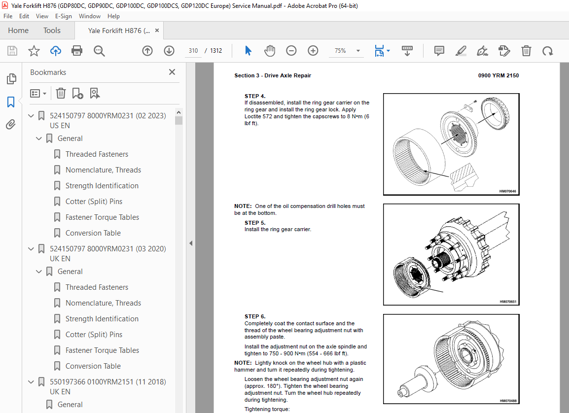
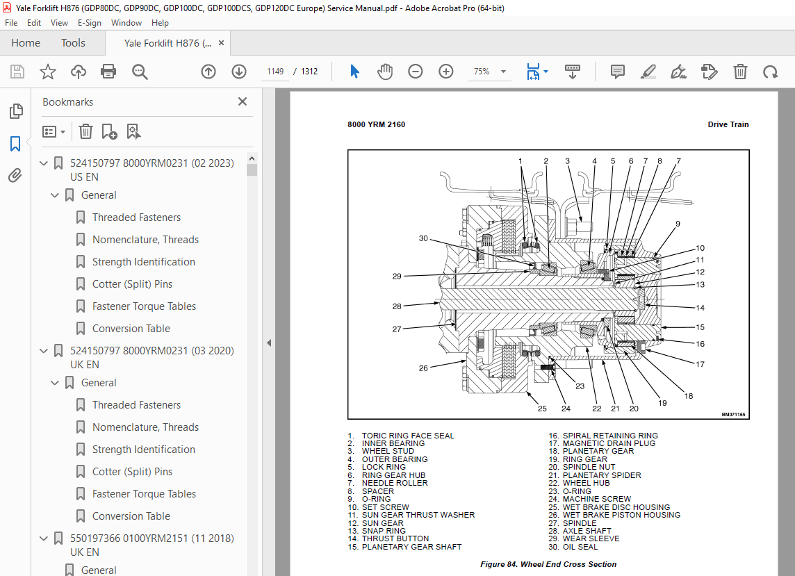
TABLE OF CONTENTS:
Yale Forklift H876 (GDP80DC, GDP90DC, GDP100DC, GDP100DCS, GDP120DC Europe) Service Manual – PDF DOWNLOAD
524150797 8000YRM0231 (02 2023) US EN 1
General 7
Threaded Fasteners 7
Nomenclature, Threads 7
Strength Identification 8
Cotter (Split) Pins 9
Fastener Torque Tables 14
Conversion Table 16
524150797 8000YRM0231 (03 2020) UK EN 23
General 27
Threaded Fasteners 27
Nomenclature, Threads 27
Strength Identification 28
Cotter (Split) Pins 29
Fastener Torque Tables 34
Conversion Table 36
550197366 0100YRM2151 (11 2018) UK EN 43
General 51
Precautions 51
Series Code / Model Designation Reference Table 51
Section 1 – Cab Repair 51
Operator’s Cab Assembly 51
Tilting the Cab 53
Raising 53
Lowering 54
Remove 54
Install 56
Cab Tilt System 58
Hand Tilt Pump 58
Remove 58
Install 58
Electric Tilt Pump 59
Remove 59
Install 59
Cab Tilt Cylinder 59
Remove 59
Disassemble 60
Clean 62
Inspect 62
Assemble 62
Install 62
Latch 63
Remove 63
Install 63
Cab Windows 64
Window Replacement 64
Front Window 65
Remove 65
Install 65
Rear Window 65
Remove 65
Install 65
Top Window 66
Remove 66
Install 66
Door, Upper/Lower Window 67
Remove 67
Install 67
Sliding Window and Sliding Tracks 67
Remove 67
Install 69
Weather Strip Replacement 69
Window Stopper Replacement 69
Window Seal Replacement 70
Sliding Window Frame 70
Remove 70
Install 70
Window Wipers 70
Window Wiper Assembly Replacement 70
Remove 70
Install 71
Window Wiper Motor Replacement 71
Front Window Wiper Motor 71
Install 71
Rear Window Wiper Motor Assembly 72
Remove 72
Install 72
Top Window Wiper Motor Assembly 72
Remove 72
Install 72
Window Washer System 72
Window Washer Reservoir and Pumps 72
Remove 72
Install 73
Window Washer Hoses 73
Hoses for Top and Rear Window 73
Install 74
Window Washer Spray Nozzles 75
Front Window 75
Remove 75
Install 75
Rear Window 75
Remove 75
Install 75
Top Window 75
Remove 75
Install 75
Cab Door Assembly 76
Cab Door 76
Remove 76
Install 76
Door Hinge 77
Remove 77
Install 77
Door Latch 78
Remove 78
Install 78
Door Handle 78
Remove 78
Install 78
Door Release 79
Remove 79
Install 79
Door Push Button 79
Remove 79
Install 80
Steering Wheel and Steering Column Assembly 80
Steering Wheel and Horn 80
Remove 80
Install 82
Steering Column Assembly 82
Remove 82
Install 83
Adjustment Handle 83
Remove 83
Install 83
Main Warning Lights 84
Remove 84
Install 84
Shift Lever 84
Remove 84
Install 84
Turn Signal Lever 84
Remove 84
Install 84
Pedals 85
Brake and Inching Pedal 85
Remove 85
Install 85
Accelerator Pedal and Sensor 86
Remove 86
Install 86
Adjust Sensor 86
Instrument Panel 86
Key Switch and Override Key Switch 86
Remove 86
Install 87
12V Power Socket 87
Remove 87
Install 87
Electric-Operated Heat Control and Air Recirculation Control (Airco Only) 87
Remove 87
Install 88
Cable-Operated Heater Control (Heater Only) 88
Remove 88
Install 89
Air Conditioning Switch Replacement 89
Instrument Panel Rocker Switches Replacement 89
Parking Brake Switch 89
Remove 89
Install 90
Indicator Display Replacement 90
Instrument Panel Top Console 90
Remove 90
Install 91
Seat Assembly 91
Remove 91
Install 91
Seat Components 92
Seat Cushion 92
Remove 92
Install 92
Back Cushion 92
Remove 92
Install 92
Seat Suspension Replacement 93
Boot Replacement 93
Power Assist Armrest 116
Release Cable 116
Remove 116
Install 116
Gas Spring 117
Remove 117
Install 117
Joystick 117
Remove 117
Install 117
Electrical Levers 118
Remove 118
Install 118
Armrest Rocker Switches 118
Remove 118
Install 118
Armrest Top Cover 119
Remove 119
Install 119
Cab Interior 119
Floor Mat 119
Front Floor Mat 119
Remove 119
Install 119
Rear Floor Mat 120
Remove 120
Install 120
Radio Console 120
Remove 120
Install 121
Air Duct Replacement 121
Remove Front 121
Remove Rear 121
Install 122
Accessories 123
Mirror Replacement 123
Sunshade Replacement 123
Top 123
Rear 123
Map Light Replacement 123
Interior Fan Replacement 124
Training Seat 124
Field Installation 124
Remove 124
Checks and Adjustments 124
Label Check and Replacement 124
Cab Tilt System Oil Level Check 124
Door Striker Pin Adjustment 125
Brake and Inching Pedal Adjustment 126
Section 2 – Cab Heater and Air Conditioner Repair 126
Heater Assembly 127
Access 127
Remove 127
Install 128
Heater Parts 129
Heater Core 129
Remove 129
Install 130
Blower 130
Remove 130
Install 131
Water Valve 132
Remove 132
Install 132
Push/Pull Cable 133
Water Valve Cable 133
Remove 133
Install 133
Heater/Air Conditioning Assembly 134
Remove 134
Install 135
Heater/Air Conditioner Parts 135
Vent Door 135
Remove 135
Install 136
Heater Core 136
Remove 136
Install 137
Evaporator Core 138
Remove 138
Install 139
Blower 140
Remove 140
Install 140
Thermostat 141
Remove 141
Install 142
Water Valve 142
Remove 142
Install 143
Filtration 144
Fresh Air Filter 144
Remove 144
Install 144
Recirculation Air Filter 144
Remove 144
Install 145
Air Conditioning Technical Detail 145
Maintenance Procedures and Required Equipment 146
Maintenance Procedures 146
Installing Manifold Gauges 146
Refrigerant Recovery 148
Refrigerant Leak Check 149
Evacuation and Dehydration 149
General 149
Preparation 149
Procedure For Evacuation and DehydratingSystem (Triple Evacuation) 149
Procedure For Evacuation and DehydratingSystem (One Time Evacuation) 149
Adding Refrigerant to a System 150
Checking Refrigerant Charge 150
Adding Full Charge 150
Adding Partial Charge 150
Filter Drier 151
550197367 0900YRM2150 (09 2018) UK EN 157
Series Code / Model Designation Reference Table 165
General 165
Precautions 165
Special Tools 165
Section 1 – Drive Shaft Repair 167
Drive Shaft Assembly 167
Remove 167
Disassemble 169
Clean and Inspect 169
Assemble 169
Install 170
Section 2 – Transmission Repair 171
Transmission Assembly 171
Remove 171
Clean and Inspect 181
Housings 181
Oil Seals and Gaskets 181
Bearings 181
Gears and Shafts 182
Install 192
Oil Pump 194
Clutch Packs 198
Clutch K3, Third Speed 198
Clutch K2, Second Speed 211
Clutch KR, Reverse 226
Clutch KV, Forward 241
Input Shaft 255
Clutch K1, First Speed 257
Transmission Oil Filter Assembly 272
Clean 273
Inspect 273
Transmission Control Valve 274
Clean 279
Inspect 279
Transmission Test and Calibration 286
Precautions 286
Transmission Oil Sampling 286
Preparation 286
Sampling Procedure 286
Stall Test 287
Stall Test Procedure 287
Inch Pedal Calibration 287
Brake and Inch Pedal Adjustment 288
Inch Sensor Adjustment 288
Inch Pedal Calibration 289
Preparation 289
Calibration Procedure Using the Calibration Switch 289
Calibration Procedure Using the Testman software 289
Inch Pedal Calibration Fault Codes 289
Clutch Calibration 290
Manual Clutch Calibration Procedure 290
Testman Clutch Calibration Procedure 292
Control Valve Pressure Checks 292
Speed and Temperature Sensor Checks 294
Electrical Specifications 295
Section 3 – Drive Axle Repair 297
Drive Axle Assembly 297
Remove 297
Install 299
Drive Axle Components 300
Planetary Gear Assembly 300
Preparations 301
Repairing and Replacing Parts 306
Welding 307
Clean 307
Ground or Polished Parts 307
Parts With Rough Finishes 307
Axle Assemblies 307
Drying Cleaned Parts 308
Preventing Corrosion 308
Inspect 308
Service Brake Assembly 313
Remove Service Brake 315
Clean 320
Ground and Polished Parts 320
Parts With Rough Finish 320
Wet Disc Brake and Axle Assembly 320
Inspect 320
Face Seals 320
Disc 321
Wear Limits 321
Replace Parts 322
Differential Assembly 328
Preparations 330
Remove 330
Differential Carrier From Axle Housing 330
Main Differential and Ring Gear Assembly From Differential Carrier 331
Drive Pinion and Pinion Carrier From Differential Carrier 333
Disassemble 335
Main Differential and Ring Gear Assembly 335
Drive Pinion, Bearings, and Pinion Carrier 337
Clean and Inspect 340
Assemble 340
Drive Pinion, Bearings, and Pinion Carrier 340
Pinion Bearings Preload Adjustment 343
Press Method 343
Flange Method 344
Triple-Lip Oil Seal 344
Pinion Carrier Shim Set Thickness Adjustment (Depth of Pinion) 346
Main Differential and Ring Gear Assembly 348
Differential Gears Rotating Torque 350
Install 351
Differential and Ring Gear Assembly 351
Differential Bearings Preload Adjustment 353
Method 1 353
Method 2 354
Ring Gear Runout Check 355
Ring Gear Backlash Adjustment 355
Tooth Contact Pattern Check 357
Thrust Screw Installation and Adjustment 360
Differential Carrier Into Axle Housing 360
Parking Brake 361
Preparations 362
Parking Brake Caliper 363
Remove 363
Disassemble 363
Clean and Inspect 363
Assemble 364
Install 364
Parking Brake Caliper Pads 365
Remove 365
Install 365
Drive Axle Checks and Adjustments 365
Oil Drain and Refill Procedures 365
Differential 365
Drain 365
(Re)Fill 366
Hub Assembly 366
Drain 366
(Re)Fill 366
Service Brake 366
Drain 366
(Re)Fill and De-aerate 367
Wheel Bearing Preload 367
Adjust 367
Parking Brake Adjustments 367
Parking Brake Bleed 367
Parking Brake Emergency Release 368
Park Brake Selector Valve Check 368
Park Brake Selector Valve Coil Check 368
Accumulator Pre-Charge Check 368
Parking Brake Pads Adjustment 370
Condition Check, Shuttle Valve L in the Main Control Valve 370
Condition Check, Shuttle Valve N in the Main Control Valve 371
Condition Check, Priority Valve on the Main Control Valve 371
Pressure Check, Port MLS1 371
Drive Axle Torque Specifications 372
Section 4 – Steering Axle Repair 374
Steering Axle Assembly 374
Remove 374
Install 375
Steering Axle Components 375
Steering Cylinder 375
Remove 375
Install 376
Tie Rod 377
Remove 377
Clean and Inspect 377
Install 377
Hubs 377
Remove and Disassemble 377
Clean and Inspect 377
Assemble and Install 377
Spindle 378
Remove 378
Clean 379
Assemble and Install 379
Steering Axle Checks and Adjustments 379
Maximum Steering Angle Adjustment 379
Torque Specifications 380
Steering Axle 380
Wheel Nuts 380
Steering Cylinder 380
Section 5 – DEF System Repair 381
DEF System Assembly 381
DEF System Components 381
DEF Tank 381
Remove 381
Install 382
DEF Tank Fill Cap 382
DEF Tank Unit 382
Remove 382
Install 382
DEF Tank Suction Filter 383
Replace 383
DEF Pump Assembly 384
Remove 384
Install 384
DEF Pump Filter 384
Replace 384
DEF Dosing Valve 385
Remove 385
Install 386
DEF System Checks and Adjustments 386
DEF Dosing Valve 386
DEF Pump 386
550197368 0700YRM2152 (11 2018) UK EN 389
Series Code / Model Designation Reference Table 393
General 393
Precautions 393
Cooling System 394
Cooling Core Assembly 394
Remove 395
Disassemble 399
Assemble 399
Install 399
Cooling System Components 402
Cooling Fan 402
Remove 402
Install 402
Drive Belt 403
Remove 403
Install 403
Belt Tensioner 404
Inspect 404
Remove 404
Install 404
Water Pump 404
Inspect 404
Remove 404
Install 405
Thermostat 405
Remove 405
Inspect 405
Install 406
Checks and Adjustments 406
Cooling System Checks 406
Basic Checks 406
Coolant Quality Checks 407
Coolant Flow Checks 407
Thermostat 407
Water Pump 408
Cooling Core Efficiency 408
Cooling Core Flow Restrictions 409
Engine Leak Tests 409
External Leak Test 409
Check for Coolant Leak Into The Engine Oil Sump 410
Combustion Leak Test 411
Engine Cooling System Maintenance 411
Draining the Engine Cooling System 411
Filling the Engine Cooling System 412
Flushing the Engine Cooling System 412
Cleaning the Engine Cooling System 413
550197369 1900YRM2149 (03 2020) UK EN 417
Series Code / Model Designation Reference Table 425
Section 1 – Hydraulic System Repair 425
Main Control Valve 425
Main Control Valve Assembly 425
Clean 428
Inspect 428
Assemble 428
Install 429
Priority Valve (A) 431
Remove 431
Clean 431
Inspect 431
Component Functionality Test 431
Install 431
Check Valve (K) 431
Remove 431
Clean 431
Inspect 431
Component Functionality Test 431
Install 431
Check Valve (I) 431
Remove 431
Clean 431
Inspect 432
Component Functionality Test 432
Install 432
Check Valve (Q) 432
Remove 432
Clean 432
Inspect 432
Component Functionality Test 432
Install 432
Screen Cartridge (O) 432
Disassemble 432
Component Functionality Test 432
Assemble 432
Shuttle Valves (L) and (M) 433
Remove 433
Clean 433
Inspect 433
Component Functionality Test 433
Install 433
Logic Valve (N) 434
Remove 434
Clean 434
Inspect 434
Component Functionality Test 434
Install 434
Full Flow Relief Valve (C) (Relief Spool) 434
Remove 434
Clean 434
Inspect 435
Assemble 435
Install 435
Pilot Supply Valve (F) 435
Remove 435
Clean 435
Inspect 435
Assemble 435
Component Functionality Test 435
Install 435
Load Sense (LS) Relief Valve (H) and Full Flow Relief Valve (G) 435
Remove 435
Clean 435
Inspect 436
Component Functionality Test 436
Install 436
Load Sense Relief Valve (H) Adjustment 436
Full Flow Relief Valve (G) Adjustment 436
Load Sense Selector Valve (D) 436
Remove 436
Clean 436
Inspect 437
Assemble 437
Install 437
Lift Pressure Selector Valve (B) 437
Remove 437
Clean 437
Inspect 438
Assemble 438
Install 438
Electrical Actuation Module 438
Remove 438
Clean 438
Inspect 438
Assemble 438
Install 438
Manual End Cap 440
Remove 440
Clean 440
Inspect 440
Assemble 440
Install 440
Emergency Lowering Valve 440
Remove 440
Clean 441
Inspect 441
Install 441
Carriage Valve Assembly 441
Remove 441
Disassemble 442
Clean and Inspect 442
Assemble 442
Install 443
Tilt Lock Valve 443
Remove 443
Clean 444
Inspect 444
Assemble 444
Install 444
Lowering Control Valve 444
Remove 444
Clean 445
Inspect 445
Install 445
Variable Displacement Pump (Primary and Secondary) 446
Remove 446
Clean 446
Inspect 446
Install 446
Load Sense and Pressure Controller Valve on Pump 448
Remove 448
Clean 448
Inspect 448
Assemble 448
Install 448
Hydraulic Checks and Adjustments 448
Adjustment of Standby Pressure on Variable Displacment Pumps 448
Preparation 448
Measure 449
Adjust 449
Hydraulic System Torque Specifications 451
Section 2 – Steering System Hydraulics Repair 452
Steering Control Unit 452
Remove 452
Install 453
Steering Cylinder 453
Remove 453
Clean and Inspect 455
Assemble and Install 456
Steering System Torque Specifications 456
Section 3 – Brake System Hydraulics Repair 457
Brake Treadle Valve 457
Remove 457
Install 457
Brake System Accumulator 458
Remove 458
Gas Filling Procedure 458
Install 459
Pre-Charge Filling 459
Parking Brake 461
Parking Brake Caliper 461
Remove 461
Disassemble 462
Clean and Inspect 462
Assemble 462
Install 463
Parking Brake Caliper Pads 463
Remove 463
Install 464
Parking Brake Adjustment 464
Parking Brake Bleed 464
Parking Brake Emergency Release 464
Brake Flow Distribution Manifold 465
Remove 465
Disassemble 466
Clean and Inspect 466
Assemble 466
Install 466
Brake Control Manifold 467
Remove 467
Orifices (F) and (G) 468
Disassemble 468
Assemble 468
Orifice (H) 468
Disassemble 468
Assemble 468
Unloading Valve (B) 468
Disassemble 468
Assemble 469
Screen 469
Disassemble 469
Assemble 469
Check Valve (E) 469
Disassemble 469
Assemble 469
Pressure Reducer Valve (C) 470
Disassemble 470
Assemble 470
Park Brake Selector Valve (A) 470
Disassemble 470
Assemble 470
Install 471
Gear Pump 471
Remove 471
Disassemble 472
Clean 473
Inspect 473
Assemble 474
Install 475
Brake System Checks and Adjustments 475
Precautions 475
Park Brake Selector Valve Check 475
Park Brake Selector Valve Coil Check 476
Accumulator Pre-Charge Check 476
Parking Brake Adjustment 477
Condition Checks 477
Check – Shuttle Valve (L) on Main Control Valve 477
Check – Shuttle Valve (N) on Main Control Valve 477
Check – Priority Valve on Main Control Valve 478
Pressure Checks 478
Check – Check Port MLS1 478
Brake System Torque Specifications 479
Section 4 – Cylinder Repair 480
Front End Cylinders 480
Side Shift Cylinder 480
Disassemble 480
Clean and Inspect 480
Assemble 481
Fork Positioner Cylinder 481
Disassemble 481
Clean and Inspect 482
Assemble 482
Tilt Cylinders 482
Disassemble 482
Clean and Inspect 483
Assemble 483
Lift Cylinders 484
Disassemble 484
Clean and Inspect 485
Assemble 485
Attachment Cylinders 485
Side Shift Cylinder 485
Disassemble 485
Clean 486
Inspect 486
Assemble 486
Extension Cylinder 486
Disassemble 486
Clean 487
Inspect 487
Assemble 487
Twist Lock Cylinders 488
Disassemble 488
Clean and Inspect 488
Assemble 488
550197369 1900YRM2149 (05 2023) US EN 491
Series Code / Model Designation Reference Table 501
Section 1 – Hydraulic System Repair 502
Main Control Valve 502
Main Control Valve Assembly 502
Clean 504
Inspect 505
Assemble 505
Install 505
Priority Valve (A) 507
Remove 507
Clean 507
Inspect 508
Component Functionality Test 508
Install 508
Check Valve (K) 508
Remove 508
Clean 508
Inspect 508
Component Functionality Test 508
Install 508
Check Valve (I) 508
Remove 508
Clean 508
Inspect 509
Component Functionality Test 509
Install 509
Check Valve (Q) 509
Remove 509
Clean 509
Inspect 509
Component Functionality Test 509
Install 509
Screen Cartridge (O) 509
Disassemble 509
Component Functionality Test 509
Assemble 509
Shuttle Valves (L) and (M) 510
Remove 510
Clean 510
Inspect 510
Component Functionality Test 510
Install 510
Logic Valve (N) 511
Remove 511
Clean 511
Inspect 511
Component Functionality Test 511
Install 511
Full Flow Relief Valve (C) (Relief Spool) 511
Remove 511
Clean 511
Inspect 512
Assemble 512
Install 512
Pilot Supply Valve (F) 512
Remove 512
Clean 512
Inspect 512
Assemble 512
Component Functionality Test 512
Install 512
Load Sense (LS) Relief Valve (H) and Full Flow Relief Valve (G) 512
Remove 512
Clean 512
Inspect 513
Component Functionality Test 513
Install 513
Load Sense Relief Valve (H) Adjustment 513
Full Flow Relief Valve (G) Adjustment 513
Load Sense Selector Valve (D) 513
Remove 513
Clean 513
Inspect 514
Assemble 514
Install 514
Lift Pressure Selector Valve (B) 514
Remove 514
Clean 514
Inspect 515
Assemble 515
Install 515
Electrical Actuation Module 515
Remove 515
Clean 515
Inspect 516
Assemble 516
Install 516
Manual End Cap 517
Remove 517
Clean 517
Inspect 517
Assemble 517
Install 517
Emergency Lowering Valve 517
Remove 517
Clean 518
Inspect 518
Install 518
Carriage Valve Assembly 518
Remove 518
Disassemble 519
Clean and Inspect 519
Assemble 519
Install 520
Tilt Lock Valve 520
Remove 520
Clean 521
Inspect 521
Assemble 521
Install 521
Lowering Control Valve 521
Remove 521
Clean 522
Inspect 522
Install 522
Variable Displacement Pump (Primary and Secondary) 523
Remove 523
Clean 523
Inspect 523
Install 523
Load Sense and Pressure Controller Valve on Pump 525
Remove 525
Clean 525
Inspect 525
Assemble 525
Install 525
Hydraulic Checks and Adjustments 525
Adjustment of Standby Pressure on Variable Displacment Pumps 525
Preparation 525
Measure 526
Adjust 526
Hydraulic System Torque Specifications 527
Section 2 – Steering System Hydraulics Repair 528
Steering Control Unit 528
Remove 528
Install 529
Steering Cylinder 529
Remove 529
Clean and Inspect 531
Assemble and Install 532
Steering System Torque Specifications 532
Section 3 – Brake System Hydraulics Repair 533
Brake Treadle Valve 533
Remove 533
Install 533
Brake System Accumulator 534
Remove 534
Gas Filling Procedure 534
Install 535
Pre-Charge Filling 535
Parking Brake 537
Parking Brake Caliper 537
Remove 537
Disassemble 538
Clean and Inspect 538
Assemble 538
Install 539
Parking Brake Caliper Pads 539
Remove 539
Install 540
Parking Brake Adjustment 540
Parking Brake Bleed 540
Parking Brake Emergency Release 540
Brake Flow Distribution Manifold 541
Remove 541
Disassemble 542
Clean and Inspect 542
Assemble 542
Install 542
Brake Control Manifold 543
Remove 543
Orifices (F) and (G) 544
Disassemble 544
Assemble 544
Orifice (H) 544
Disassemble 544
Assemble 544
Unloading Valve (B) 544
Disassemble 544
Assemble 545
Screen 545
Disassemble 545
Assemble 545
Check Valve (E) 545
Disassemble 545
Assemble 545
Pressure Reducer Valve (C) 545
Disassemble 545
Assemble 546
Park Brake Selector Valve (A) 546
Disassemble 546
Assemble 546
Install 547
Gear Pump 547
Remove 547
Disassemble 548
Clean 549
Inspect 549
Assemble 550
Install 551
Brake System Checks and Adjustments 552
Precautions 552
Park Brake Selector Valve Check 552
Park Brake Selector Valve Coil Check 552
Accumulator Pre-Charge Check 552
Parking Brake Adjustment 553
Condition Checks 554
Check – Shuttle Valve (L) on Main Control Valve 554
Check – Shuttle Valve (N) on Main Control Valve 554
Check – Priority Valve on Main Control Valve 554
Pressure Checks 555
Check – Check Port MLS1 555
Brake System Torque Specifications 555
Section 4 – Cylinder Repair 556
Front End Cylinders 556
Side Shift Cylinder 556
Disassemble 556
Clean and Inspect 556
Assemble 557
Fork Positioner Cylinder 557
Disassemble 557
Clean and Inspect 558
Assemble 558
Tilt Cylinders 558
Disassemble 558
Clean and Inspect 559
Assemble 559
Lift Cylinders 560
Disassemble 560
Clean and Inspect 561
Assemble 561
Attachment Cylinders 561
Side Shift Cylinder 561
Disassemble 561
Clean 562
Inspect 562
Assemble 562
Extension Cylinder 563
Disassemble 563
Clean 564
Inspect 564
Assemble 564
Twist Lock Cylinders 564
Disassemble 564
Clean and Inspect 565
Assemble 565
550197370 2200YRM2153 (09 2018) UK EN 567
Series Code / Model Designation Reference Table 573
General 573
Section 1 – Electrical 573
General Fault Finding 573
Preparation 573
Define the Problem Area 573
Identify Possible Causes of Malfunction 573
Determine the Most Probable Cause 573
Fuse Check 573
Wiring Check 574
Component Check 574
Repair and Test 574
Harnesses and Connectors 574
Harnesses Overview 574
Harness Connectors and Terminals 576
Frame Harness Connectors 576
Side Console Harness Connectors 578
Mast Harness Connectors 581
Closed Cab Harness Connectors 582
Steering Column/Cab Underfloor Harness Connectors 584
Armrest Harness Connectors 585
Cab Tilt Harness Connectors 587
Cab Lights Harness Connectors (LH harness shown) 588
ECM Harness Connectors (Tier 3/Stage IIIA) 588
EAS/ECM Harness Connectors (Tier 4F/Stage IV) 589
DEF Tank Harness Connectors (only Tier 4F/Stage IV) 590
Powertrain Harness Connectors 591
Hoodspine Harness Tier 3/Stage IIIA Connectors 592
Hoodspine Harness Tier 4F/Stage IV Connectors 593
Carriage Harness Connectors 594
Rear Harness Connectors 595
Wire Harness Identification and Connector Location 596
Fuses, Relays and Fly-Back Diodes 605
Main Fuses and Relays 605
Fuse Panel Overview 607
Relay Overview 610
Flyback Diodes 612
CANbus Circuit 612
Greasing System Electrical 613
Section 2 – Software 616
Hydraulic Control System 616
Safety precautions and tips 616
List of abbreviations 616
Installing the Hydraulic User Interface Program 617
Starting the Hydraulic User Interface Program 617
Truck selection window 617
Service Tool instructions 619
Tooltips 619
Parameter instructions 621
Basic screen layout 621
System Navigator 622
Warning screen/Language selection 624
Truck Configuration 626
Truck Configuration 628
Profile Setting 628
Hydraulic/Drive Priority 628
Options 628
Unit selection 629
Upload/download page 629
Installed Features 629
High Temperature Protection 630
Dynamic Lowering Control 631
Dynamic Lowering Profile 632
Vehicle Speed Limiter 633
Loaded Speed Limiter 633
Conditional Speed Limiter 634
ECH Speed Limiter 635
Anti-Stall 636
Hoist Tilt Aux Anti-Stall 637
Cold Temperature Protection 639
Automatic Throttle Up 641
ECO Mode and Engine Speed Limit 642
Hibernate Idle 644
Second Pump Control 646
Automatic Engine Shutdown 647
Hoist Pressure Sensor 648
Loaded/Unloaded Detection 649
Operator Input 650
Auto Calibration 651
Flow settings 652
Valve settings 653
Ramp Settings 654
Diagnostics 655
Vehicle Information 657
Controller Configuration 658
Pin Status 659
Brakes 660
Hydraulics 661
Input and Output 662
Aux Pin Configuration 663
Active Errors 664
Error History Page 665
Fault Cause PVE Actuator 666
Controller pinning 667
File Uploads/Downloads 668
Connecting to the Hydraulic Control Unit 668
Setup a connection 668
Check the current software version 674
Download a P1T (Parameter-file) 676
Download a ROP file 677
Tips and Tricks 679
Controller Identification 679
Truck Configuration Options 681
Section 3 – Controls 685
Instrument Panel 686
Central Warning Lights 686
Instrument Panel Overview 687
Instrument Panel Connectors 688
Fault Codes on LCD Display 690
Fault Code Mode 690
Transmission Calibration 690
Fault Code Log Mode 690
Get Access to the Fault Code Log 690
Clear the Fault Codes logged in the Display 691
Exit the Fault Code Log 691
550197371 2400YRM2154 (10 2018) UK EN 695
Series Code / Model Designation Reference Table 699
General 699
Greasing System 700
Grease Pump Assembly 700
Remove 701
Install 701
Greasing System Components 701
Grease Line Identification 701
Refilling the Grease Reservoir 712
Test Cycles Using the Button on the Pump 712
Bleeding the Pump 712
Bleeding the System 713
Minimum-Level Switch 714
Solenoid Valve 715
Pump Unit 719
Electric Pump Motor 724
Thread Adapter 729
Remove 729
Checks and Adjustments 730
Test Procedures 730
Check pressure switch (valve) and cable 730
Check pump and 5/2-way valve 730
Check for Internal System Leaks 731
Technical Data 732
Pump Unit 732
Grease Recommendations 732
Electrical 732
Torque Specifications 735
550197372 4000YRM2155 (10 2018) UK EN 739
Series Code / Model Designation Reference Table 745
General 745
Safety Procedures 745
When Working on the Hydraulic System 745
Section 1 – Forks and Carriage Repair 746
Forks 746
Pin-Type Forks 746
Remove 746
Install 747
Hook-Type Forks 748
Remove 748
Install 748
Fork Guide And Fork Pin 748
Remove 748
Install 749
Fork Hanger 749
Remove 749
Install 749
Carriage Assembly 751
Carriage Types 751
Remove 753
Install 754
Carriage Components 756
Carriage Bearing Blocks 756
Remove 756
Install 757
Carriage Load Rollers 758
Replace 758
Side Shift Cylinder 758
Remove 758
Install 759
Fork Positioner Cylinder 759
Remove 759
Install 760
Carriage Valve 760
Remove 760
Install 761
Section 2 – Container Attachment Repair 763
Container Attachment Assembly 763
Remove 763
Install 764
Spreader from Carriage 765
Container Attachment Components 767
Wear Pads 767
Extension Beam Wear Pads 767
Replace 767
End Beam Wear Pads 769
Check and Replace 769
Carriage Wear Pads 770
Upper Front Wear Pads 771
Upper Rear Wear Pads 771
Lower Support Wear Pads 772
Lower Rear Wear Pads 772
Extension Cylinder 772
Remove 772
Install 773
End Beam 773
Remove 773
Install 773
Extension Beam 773
Remove 773
Install 774
Side Shift Cylinder 774
Remove 774
Install 775
Twist Lock Cylinder 775
Remove 775
Install 777
Twist Locks 777
Remove and Disassemble 777
Clean 778
Inspect 778
Assemble and Install 779
Checks and Adjustments 779
Twist Lock Seated Signal Sensor Adjustment 779
Twist Lock Locked/Unlocked Signal Sensor Adjustment 780
Twist Lock Angle Adjustment 781
Overlowering Protection Sensor Adjustment 781
Electrical Component Checks 781
Printed Circuit Boards (PCB) 782
Solenoids 782
Proximity Switches 782
Section 3 – Mast Repair 783
Mast Assembly 783
Two-Stage Mast 783
Remove 783
Disassemble 785
Assemble 787
Install 788
Mast Components 790
Lift Chains and Top Chain Anchor 790
Remove 790
Install 790
Chain Anchor On Carriage 791
Remove 791
Install 791
Chain Sheave 792
Remove 792
Install 792
Header Hoses and Mast Hoses 792
Remove 792
Install 794
Electric Mast Cable 794
Remove 794
Install 795
Hose Sheave 795
Remove and Disassemble 795
Assemble and Install 795
Inner and Outer Mast Load Rollers 795
Replace 795
Mast Bearing Blocks 796
Remove 796
Install 796
Lift Cylinders 797
Remove 797
Install 798
Tilt Cylinders 799
Remove 799
Install 800
Mast Checks and Adjustments 800
General Checks 800
Mast Condition Check 800
Mast Operation Check 801
Tilt Lock Valve Check 801
Fork Inspection and Adjustment 801
Lift Chain Inspection 802
Lift Chain Lubricant Requirements 803
Lift Chain Lubrication Procedure 803
Leak Checks 803
Mast Vertical Creep 803
Mast Tilt Drift 804
Adjustments 804
Lift Cylinder Shimming 804
Lift Chain and Fork Height Adjustment 805
Lift Chain Adjustment Procedure 806
Header Hose Tension Adjustment 807
Electric Mast Cable Tension Adjustment 807
Tilt Lock Valve Adjustment 807
Tilt Cylinder Backward Tilt Angle Adjustment 808
Mast Support Pad Adjustment 808
Torque Specifications 809
Tightening Torques 809
550197373 8000YRM2147 (01 2020) UK EN 815
Series Code / Model Designation Reference Table 821
General 821
Serial Number Data 821
Truck Handling Procedures 822
Moving and Towing a Lift Truck 822
Precautions 822
Towing the Truck 823
Putting a Lift Truck on Blocks 823
Raising the Drive Tires 823
Raising the Steering Tires 824
Cleaning a Lift Truck 824
Safety Procedures Before Starting Maintenance 825
Making Checks From the Driver Seat with Engine Running 825
Fire Hazard 826
Hydraulic Service Switch 826
Transmission Calibration Switch 826
Wait 100 Seconds Before Disconnecting Battery 826
Periodic Maintenance Schedule 827
Daily Inspection 828
Daily Condition Checks 828
Daily Fluid Level Checks 828
Daily Checks from the Driver Seat with Engine Running 829
Initial Inspection 830
First Inspection after First 100 Hours of Operation 830
First Inspection after First 250 Hours of Operation 831
Periodic Maintenance 831
Inspect and Adjust 831
Annual Inspection 833
Lubricate 835
Change 836
Periodic Maintenance Procedures 837
Air Conditioning System 837
Attachment 837
Automatic Greasing System (Optional) 837
Greasing System Display 837
Greasing System 838
Greasing System Filter 838
Brake Cooling Filter 839
Brake System Accumulator 839
Cab Air Filter 840
Cab Door Hinges 840
Control Levers, Switches, and Pedals 840
Cooling System 840
Coolant Hoses 840
Coolant Level 841
Coolant Quality 841
Cooling Fan 841
Crankcase Breather Element (Tier 4F/Stage IV Only) 842
Diesel Exhaust Fluid (DEF) System 842
DEF Pump Filter 842
DEF Tank Fill Cap 843
DEF Tank Suction Filter 843
Drive Axle, Differential and Axle Hub Assembly 844
Check Oil level 844
Change Oil 844
Drive Wheel Hub Bearing Preload 844
Drive Shaft 844
Engine Air Filter 845
Engine Air Intake Piping and Charge Air Piping 845
Engine and Transmission Mounts 846
Engine Compartment 846
Engine Drive Belt 846
Engine Drive Belt Tensioner and Pulleys 847
Bearing Condition 847
Pulley Alignment 847
Tensioner Condition 847
Engine Oil 849
Engine Oil Level 849
Engine Oil and Engine Oil Filter 849
Engine Valve Adjustment 850
Fault Codes 852
Forks 853
Fork Pins, Carriage Pins, and Carriage Sliding Surfaces 853
Frame, Mast, Carriage and Attachment 854
Fuel, Oil, DEF, or Coolant Leaks 854
Fuel/Water Separator and Final Fuel Filter 854
Fuel Tank Breather 855
Header Hose Assembly 855
Horn, Gauges, Lights, Alarms and Control System 856
Hydraulic System Oil 856
Hydraulic Oil Testing Procedures 857
Hydraulic Oil Replacement 857
Hydraulic Tank Breather 858
Hydraulic Tank Return Filter 858
Inching Pedal Sensor Calibration 859
Lift Chains 859
Check and Lubricate Lift Chains 859
Adjust Lift Chains 859
Inspect Lift Chains 860
Chain Elongation 861
Lift Chain Wear and Damage 861
Lift System Accumulator (Optional) 862
Load Rollers 862
Carriage Load Rollers 862
(Inner) Mast Load Rollers 862
Mast, Carriage, and Attachment 862
Mast Pivot Pins 863
Operator Presence System 863
Operator Restraint System 863
Seat Belt and Seat Rails 863
Steering Column Latch 864
Parking and Service Brakes 864
Radiator Assembly 864
Steering Axle Grease Fittings 864
King Pins 864
Tie Rod Pins 865
Steering System 865
Steering Wheel Hub Bearings 865
Remove and Disassemble 865
Clean and Inspect 866
Assemble and Install 866
Tilt Cylinder Pivot Pins 866
Transmission 866
Transmission Clutch Calibration 867
Transmission Oil Level 867
Transmission Oil and Oil Filter 867
Vibration Damper (Viscous) 868
Warning and Safety Labels 869
Windows and Mirrors 869
Windshield Washer Fluid Level 869
Wheels and Tires 869
Wheels, Tires, and Tire Pressure 869
Remove Wheels from Lift Truck 870
Adding Air Pressure to Pneumatic Tires 876
Install Wheels on Lift Truck 881
Capacities and Specifications 882
Approved Fuel and Engine Oils 882
Approved Oils, Fluids, and Grease 882
Engine Oil Viscosity 883
Lift Chain Lubricant Requirements 884
Fuses and Relays 884
Main Electrical Supply 885
Relays 887
550197374 8000YRM2148 (09 2018) UK EN 891
Series Code / Model Designation Reference Table 895
General 895
Weight and Dimensions 896
Loading Procedures 907
Loading a Truck on a Transport 907
Preparing Truck for Loading on a Trailer with Mast Installed 907
Install the Tilt Extension Brackets 907
Loading Disassembled Components 908
Unloading Procedures 909
Unloading a Truck From Transport 910
Preparing Truck with Mast Installed for Unloading from a Trailer 910
Remove the Tilt Extension Brackets 910
Lifting a Truck 910
Driving a Truck off a Trailer 911
Unloading Disassembled Components 911
Removal of Forks Attached to a Basic Truck 911
Removal of Forks Attached to the Carriage 912
Moving and Towing 913
Moving a Disabled Lift Truck 913
Precautions 913
Towing a Lift Truck 914
Safety Procedures When Working Near The Mast 915
When Working Near The Mast Always 915
Before Starting Repairs To The Hydraulic System Always 916
Truck Assembly 916
Mast Assembly 916
Preparations 916
Installing the Mast 917
Installing the Tilt Cylinders 919
Adjusting the Tilt Cylinders 919
Removing the Carriage Transport Lock 920
Connecting the Lift Cylinders 920
Connecting the Mast Supply Hoses 920
Carriage and Forks or Attachment 921
Install Carriage/Attachment 921
Connecting Hoses and Electrical Cable 922
Install Forks 922
Adjust Carriage 924
Install Cab Lights 925
Lubricate 925
General Checks After Assembly 925
Plumbing Check 926
Lubrication Check 926
Fluid Level Check 926
Functionality Check 926
Literature Package Check 926
Cleaning 926
Labels 926
Wheels and Tires 926
Remove Wheels From Lift Truck 926
Adding Air Pressure to the Tires 932
Install Wheels on Lift Truck 937
Wheel Nuts on Drive and Steer Wheels 937
Pre-Delivery 937
Adjust Timing For Automatic Engine Shut Down 937
Perform Pre-Delivery Inspection 938
Delivery 938
Instructions Operating Manual 938
Instructions Daily Maintenance 938
Handing Over Truck 938
550197375 8000YRM2158 (10 2018) UK EN 941
Series Code / Model Designation Reference Table 945
General 945
Precautions 945
Main Components 945
Air Filter Assembly (Tier 3/Stage IIIA) 945
Remove 945
Install 946
Air Filter Assembly (Tier 4F/Stage IV) 946
Remove 946
Install 947
Exhaust System (Tier 3/Stage IIIA) 948
Remove 948
Install 949
Exhaust System (Tier 4F/Stage IV) 949
Exhaust Pipes High Mount 949
Remove 949
Install 949
Exhaust Pipes and Diffuser Low Mount 950
Remove 950
Install 950
Exhaust Seal Rings 950
Selective Catalytic Reducer (SCR) 951
Remove 951
Install 951
Decomposition Reactor Tube (DRT) 951
Remove 951
Install 952
Diesel Oxidation Catalyst (DOC) 952
Remove 952
Install 952
Hood Assembly 952
Remove 952
Install 954
Running Boards, Steps and Mud Flaps 954
Hydraulic Tank 955
Remove 955
Inspect 958
Clean 958
Steam Cleaning Method 958
Chemical Solution Cleaning Method 958
Repair 959
Small Leaks 959
Large Leaks 959
Inspection after Repair 959
Install 959
Fuel Tank 961
Remove 961
Clean and Repair 963
Install 963
Engine and Transmission (Tier 3/Stage IIIA) 964
Remove 964
Precautions 964
Remove Air Conditioning Compressor 964
Drain the Engine Cooling System 965
Drain Hydraulic Oil 965
Drain Transmission Oil 966
Disconnect Drive Shaft, Fan Clutch, Tubes, Pipes, Cables, Wires and Lines 966
Remove Engine and Transmission 968
Install 970
Install Engine and Transmission 970
Install Air Conditioning Compressor 970
Connect Drive Shaft, Fan, Tubes, Pipes, Cables, Wires and Lines 971
Refill the Systems 971
Starting the Engine 972
Engine and Transmission (Tier 4F/Stage IV) 972
Remove 972
Precautions 972
Remove Air Conditioning Compressor 973
Drain the Engine Cooling System 973
Drain Hydraulic Oil 974
Drain Transmission Oil 974
Disconnect Drive Shaft, Fan Clutch, Tubes, Pipes, Cables, Wires and Lines 974
Remove Engine and Transmission 977
Install 979
Install Engine and Transmission 979
Install Air Conditioning Compressor 979
Connect Drive Shaft, Fan, Tubes, Pipes, Cables, Wires and Lines 979
Refill the Systems 979
Starting the Engine 980
Counterweight 981
Remove 981
Install 982
Label Replacement 983
550197376 8000YRM2159 (07 2019) UK EN 987
Series Code / Model Designation Reference Table 991
Electrical Schematic T3/T4 Final 992
Hydraulic Schematic 1019
550197377 8000YRM2160 (10 2018) UK EN 1027
Series Code / Model Designation Reference Table 1037
General 1037
Hydraulics 1037
Hydraulic Component Location and Identification 1037
Main Control Valve 1041
Introduction 1041
Flow Path 1041
Main Manifold 1042
Introduction 1042
Priority Valve (A) 1044
Fundamentals 1044
Description 1044
Operation 1044
Component Functionality Test 1045
Check Valve (I) 1045
Function Description 1045
Function Operation 1045
Component Functionality Test 1045
Pilot Supply Circuit 1045
Function Description 1045
Pilot Supply Valve (F) 1046
Fundamentals 1046
Function Description 1046
Function Operation 1046
Component Functionality Test 1046
Lift Pressure Selector Valve (B) 1047
Function Description 1047
Function Operation 1047
Component Functionality Test 1047
Check Valve (K) 1048
Function Description 1048
Component Functionality Test 1048
Check Valve (Q) 1048
Function Description 1048
Component Functionality Test 1048
Screen Cartridge (O) 1049
Function Description 1049
Component Functionality Test 1049
Relief Valve 1049
Function Description 1049
Load Sense Relief Valve (H) 1050
Fundamentals 1050
Functional Operation 1050
Component Functionality Test 1050
Pressure Controller on Pump 1050
Fundamentals 1050
Functional Operation 1050
Component Functionality Test 1051
Full Flow Relief Valve (C) and (G) 1051
Fundamentals 1051
Functional Operation 1051
Component Functionality Test 1052
Shuttle Valve (L) and (M) 1052
Function Description 1052
Component Functionality Test 1052
Logic Valve (N) 1053
Function Description 1053
Function Operation 1053
Load Sense Selector Valve (D) 1054
Function Description 1054
Component Functionality Test 1054
Directional Control Valve Section 1054
Functional Operation (System Level) 1055
Directional Control Valve 1056
Fundamentals 1056
Description 1056
Functional Operation 1056
Electrical Actuation Module (Solenoid End Cap) 1057
Functional Operation 1057
Component Functionality Test 1058
Lift Function 1058
Function Description 1058
Pilot-Operated Check Valve 1059
Fundamentals 1059
Function Description 1059
Function Operation 1060
Emergency Lowering Valve 1060
Function Description 1060
Lowering Control Valve 1061
Fundamentals 1061
Function Description 1061
Tilt Function 1061
Function Description 1061
Impact Relief Valve 1062
Fundamentals 1062
Function Description 1062
Counterbalance Valve 1063
Fundamentals 1063
Function Description 1063
Auxiliary Function 1063
Function Description 1063
Variable Displacement Pump 1063
Function Description 1064
Basic Functional Operation 1064
Pressure Control Valve 1065
Fundamentals 1065
Operation 1065
Load Sense Pressure Regulator 1065
Fundamentals 1065
Functional Operation 1065
Hydraulic Control System 1065
Brake System 1065
Service Brakes 1065
Park Brake 1066
Description 1066
Hydraulic Oil Flow Path 1066
Brake Accumulator Charging System 1066
Service Brake System 1066
Priority Valve 1066
Fundamentals 1066
Description 1067
Operation 1067
Brake Control Manifold 1067
Description 1068
Orifice (F) 1068
Fundamentals 1068
Description 1069
Operation 1069
Unloading Valve 1069
Fundamentals 1069
Operation 1069
Screen 1069
Description 1069
Check Valve 1070
Description 1070
Pressure Reducer Valve 1070
Fundamentals 1071
Operation 1071
Brake Accumulator 1071
Fundamentals 1071
Operation 1071
Brake Treadle Valve 1072
Fundamentals 1072
Description 1072
Operation 1072
Steering System 1072
Steering System 1072
Introduction 1072
Steering System Main Component Identification 1073
Description 1077
Hydraulic Oil Flow Path 1077
Priority Valve 1077
Fundamentals 1077
Description 1077
Operation 1077
Steering Control Unit 1078
Description 1078
Steering Control Valve 1079
Fundamentals 1079
Operation 1079
Hand Pump 1079
Fundamentals 1079
Operation 1080
LS Relief Valve 1080
Fundamental 1080
Operation 1080
Shock Valve 1080
Fundamental 1080
Operation 1080
Electrical System 1081
Electrical Schematic 1081
Schematic Location Number 1083
Electrical Components 1083
Electrical Wires 1083
Wire Identification Number 1083
Electrical Wire Colors 1084
Wire Harnesses 1085
Harness Interconnection 1087
Electrical Connectors 1087
Connector Types 1087
Connector Identification 1088
Connector Pin Numbers 1088
Connector Description 1088
Fuses 1089
Relays 1090
Flyback Diodes 1091
CAN (Controller Area Network) 1091
Troubleshooting 1093
Instrument Panel 1093
Instrument Panel Connectors 1096
LCD Display 1098
Hourmeter Mode 1098
Fault Code Mode 1098
Transmission Calibration 1099
Fault Code Log Mode 1099
Operator’s Cab 1100
Cab Structure 1100
Cab Tilt System 1102
Cab Heater/Air Conditioning 1104
Heater System 1104
General 1104
Air Conditioning 1106
General 1106
Dryer 1107
Compressor Lubrication 1108
Control Systems, Sensors, and Switches 1108
Climate Control 1110
Description 1110
Service Menu 1110
Set Up 1111
View 1 and View 2 1111
Error List 1112
Statistics 1113
Exit 1113
Temperature Sensors 1113
Troubleshooting 1114
Water Valve 1114
Troubleshooting 1114
Drive Train 1117
Transmission, Operation and Diagnostics 1117
General 1117
Clutch 1119
Operation 1120
Hydraulic Operation 1120
Clutch Valve 1121
Cooling and Lubrication 1123
Control System 1124
Transmission Control Unit (TCU) 1125
Operating Modes 1125
Normal Mode 1125
Substitute Clutch Control 1125
Limp-Home Mode 1125
Transmission Shut Down Mode 1126
TCU Shut Down Mode 1126
Transmission Exceed Codes 1126
Self-Test 1126
Fault Codes 1126
Description 1126
Fault Log Mode 1127
Access 1127
Exit 1128
Clear 1128
Fault Log Memory 1128
Fault Rectification 1128
Hydraulic Control Valve 1129
Hydraulic Control Valve Repair 1131
Solenoid Replacement 1131
Pressure Check 1131
Pressure Specifications 1132
Speed and Temperature Sensors 1133
Speed Sensors 1133
Test 1134
Temperature Sensors 1134
Shift Lever 1134
Foot Directional Control 1135
ZF Transmission Test and Calibration 1135
Transmission Test and Calibration 1135
Precautions 1135
Stall Test 1136
Description 1136
Stall Test Procedure 1136
Inch Pedal Calibration 1137
Description 1137
Calibration 1137
Brake and Inch Pedal Adjustment 1137
Inch Sensor Adjustment 1138
Inch Pedal Calibration 1139
Preparation 1139
Calibration Procedure Using the Calibration Switch 1139
Calibration Procedure Using the Testman software 1140
Inch Pedal Calibration Fault Codes 1140
Clutch Calibration 1141
Description 1141
Clutch Calibration Procedure 1141
Manual Clutch Calibration Procedure 1142
Testman Clutch Calibration Procedure 1143
Testman 1144
Description 1144
Connection 1144
Truck Configuration 1144
Configuration 1145
Limitations 1145
Capacities and Specifications 1146
Electrical Specifications 1146
Transmission Control Unit Diagram 1147
Drive Axle 1148
Planetary Gear Assembly 1148
Differential 1149
Drive Shaft 1150
Steering System 1151
Brake System 1152
Park Brake System 1152
Park Brake Selector Valve 1152
Fundamentals 1152
Operation 1152
Component Validation for Correct Operation 1153
DEF System 1153
Cooling System 1163
Description 1163
Cooling Cores 1164
Fan 1164
Fan Clutch 1165
Fan Clutch Engagement 1165
Shroud 1166
Engine Cooling System 1166
Water Pump 1167
Thermostat 1167
Expansion Tank And Radiator Cap 1168
Cab Heater 1169
Coolant 1169
DEF Heater 1169
EGR Cooler 1170
Charge Air Cooling System 1170
Transmission Oil Cooling System 1170
Hydraulic Oil Cooling System 1170
Hydraulic Oil Cooling 1170
Oil Filtration and Oil Cooling 1172
Brake Cooling 1173
Hydraulic Control System 1173
Front End Equipment 1173
Carriage 1174
Standard Pin-Type Carriage 1174
Side Shift Apron Carriage 1175
Dual Function Side Shift Fork Positioning (DFSSFP) Carriage 1176
Carriage Valve 1177
Alternating Pressure and Tank (P & T) 1177
Fixed Pressure and Tank (P & T) 1178
Fixed Pressure and Tank System (Fixed P & T) 1178
Forks 1180
Mast 1180
Tilting 1181
Lifting 1181
Operation 1182
Pilot Operated Check Valves 1182
Gland Lubrication 1183
Emergency Lowering Valve 1184
Operation 1184
Lift Chains 1185
Elongation Through Wear 1186
Speed of Wear 1186
Plate Height Wear 1187
Lubrication 1187
Restoring The Oil Film 1187
Maintenance 1187
Maintaining The Presence of Oil 1188
Corrosion Protection 1188
Requirements for Chain Lubricant 1188
Load Rollers 1189
Bearing Blocks 1189
Greasing System 1190
General 1190
Description 1190
Grease Pump Assembly 1191
Reservoir 1192
Controller 1193
Pump 1193
5/2 Solenoid Valve 1193
Divider Block 1194
Pressure Switch 1197
Greasing Cycle 1199
Stage 1 Pumping 1199
Stage 2 Pressure Retaining 1200
Stage 3 Pressure Decreasing 1200
Stage 4 Pause 1200
Display 1200
Description 1200
Control LED’s 1201
3-Digit Display 1201
Start Up 1201
Selected Duty Cycle 1202
Decimal Dot 1202
Low Grease Level 1202
Test Being Performed 1202
Fault Code 1202
Switch Button 1203
Changing the duty cycle 1203
Test Cycle Selection 1203
Activating a Single Test Cycle 1203
Activating Multiple Test Cycles 1203
Resetting Fault Codes 1203
Electrical 1204
Frame 1206
550201743 8000YRM2162 (10 2018) UK EN 1211
Series Code / Model Designation Reference Table 1215
Counterweight Weights 1215
Lift Truck Weights 1216
Mast Speeds 1216
Tire Sizes 1217
Hydraulic System 1218
Electrical System 1218
Engine Specifications 1218
Capacities 1220
Torque Specifications, General 1220
Transmission ZF 1221
Driveline and Axle 1221
Counterweight 1221
Differential 1221
Brakes 1221
Steering 1221
Wheel Nuts 1221
Hydraulic System 1221
Mast 1222
Carriage 1222
Tilt Cylinders 1222
Wiper Arms, Front 1222
Torque Specifications, Cummins Diesel 1222
Lubrication System 1223
550201744 9000YRM2163 (10 2018) UK EN 1227
Series Code / Model Designation Reference Table 1231
General 1231
SECTION 1 – Troubleshooting 1231
Cab Heater and Air Conditioning 1231
Preliminary Checks 1231
Checking System Air Output 1231
Check The Sight Glass for Bubbles 1231
Troubleshooting Procedures 1231
General System 1232
Climate Control Display Diagnostics Menu Errors 1234
Mast 1234
Attachment 1238
Troubleshooting Procedures 1238
SECTION 2 – Error Codes 1240
Cummins Engine 1240
General 1240
Fault Code Descriptions 1240
Finding Fault Code Information 1240
Normal Mode 1241
Fault Log Mode 1241
Access 1241
Exit 1242
Clear 1242
Electronic Throttle Calibration 1242
Stationary Regeneration Procedure 1242
Transmission 1268
Transmission Exceed Codes 1268
Transmission Fault Codes 1270
Hydraulic Fault Codes 1296
Automatic Greasing System Fault Codes 1307
More products