$38.95
Yale J876 (GDP190DF, GDP210DF, GDP230DF, GDP230DFS, GDP250DF, GDP280DF) Service Manual PDF
Yale Forklift J876 (GDP190DF, GDP210DF, GDP230DF, GDP230DFS, GDP250DF, GDP280DF) Service Manual – PDF DOWNLOAD
FILE DETAILS:
Yale Forklift J876 (GDP190DF, GDP210DF, GDP230DF, GDP230DFS, GDP250DF, GDP280DF) Service Manual – PDF DOWNLOAD
Language : English
Pages : 844
Downloadable : Yes
File Type : PDF
IMAGES PREVIEW OF THE MANUAL:
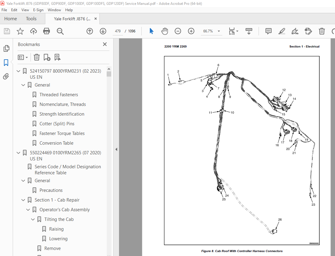
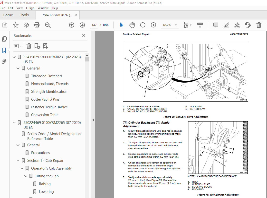
TABLE OF CONTENTS:
Yale Forklift J876 (GDP190DF, GDP210DF, GDP230DF, GDP230DFS, GDP250DF, GDP280DF) Service Manual – PDF DOWNLOAD
524150797 8000YRM0231 (02 2023) US EN 1
General 7
Threaded Fasteners 7
Nomenclature, Threads 7
Strength Identification 8
Cotter (Split) Pins 9
Fastener Torque Tables 14
Conversion Table 16
550224469 0100YRM2265 (07 2020) US EN 23
Series Code / Model Designation Reference Table 29
General 29
Precautions 29
Section 1 – Cab Repair 30
Operator’s Cab Assembly 30
Tilting the Cab 30
Raising 30
Lowering 31
Remove 32
Install 34
Cab Tilt System 35
Hand Tilt Pump 35
Remove 35
Install 36
Electric Tilt Pump 37
Remove 37
Install 38
Cab Tilt Cylinder 38
Remove 38
Install 39
Latch 40
Remove 40
Install 41
Cab Windows 41
Window Replacement 41
Front Window 41
Remove 41
Install 41
Rear Window 42
Remove 42
Install 42
Top Window 42
Remove 42
Install 42
Door Window 43
Remove 43
Install 43
Sliding Window and Sliding Tracks 43
Remove 43
Install 44
Weather Strip Replacement 44
Window Stopper Replacement 44
Sliding Window Frame 44
Remove 44
Install 44
Window Wipers 45
Window Wiper Assembly Replacement 45
Remove 45
Install 45
Front Window Wiper Motor Assembly 45
Remove 45
Install 46
Rear Window Wiper Motor Assembly 46
Remove 46
Install 46
Top Window Wiper Motor Assembly 47
Remove 47
Install 47
Window Washer System 47
Window Washer Reservoir and Pumps 47
Remove 47
Install 47
Window Washer Hoses 48
Remove 48
Install 48
Window Washer Spray Nozzles 49
Front Window 49
Remove 49
Install 49
Rear Window 49
Remove 49
Install 49
Top Window 49
Remove 49
Install 49
Cab Door Assembly 49
Cab Door 49
Remove 49
Install 50
Door Hinge 50
Remove/Install 50
Door Latch 51
Remove 51
Install 52
Door Handle 52
Remove 52
Install 52
Door Release 53
Remove 53
Install 53
Door Push Button 53
Remove 53
Install 53
Steering Wheel and Steering Column Assembly 54
Steering Wheel and Horn 54
Remove 54
Install 55
Steering Column Assembly 55
Remove 55
Install 56
Shift Lever 56
Remove 56
Install 56
Gear Selection Lever 57
Remove 57
Install 57
Turn Signal Lever 57
Remove 57
Install 57
Pedals 57
Brake and Inching Pedal 57
Remove 57
Install 58
Accelerator Pedal and Sensor 58
Remove 58
Install 58
Adjust Sensor 59
Power Assist Armrest 59
Remove 59
Install 60
Armrest Components 61
Electrical Mini-Levers 61
Remove 61
Install 61
Armrest Switch Groups 62
Remove 62
Install 62
Ignition Key Switch and Start/Stop Button Switch 63
Remove 63
Install 63
Joystick 64
Remove 64
Install 64
USB Power Socket 65
Remove 65
Install 65
12V Power Socket 65
Remove 65
Install 66
Display Replacement 66
Seat Assembly 67
Remove 67
Install 67
Initialize New Seat 68
Cab Interior 68
Floor Mat 68
Remove 68
Install 68
Radio Console 69
Remove 69
Install 69
Air Duct Replacement 69
Remove 69
Install 70
Accessories 70
Mirror Replacement 70
Sunshade Replacement 70
Top 70
Rear 71
Map Light Replacement 71
Interior Fan Replacement 71
Training Seat 71
Field Installation 71
Remove 71
Checks and Adjustments 72
Label Check and Replacement 72
Cab Tilt System Oil Level Check 72
Door Striker Pin Adjustment 73
Section 2 – Cab Heater and Air Conditioner Repair 74
Heater Assembly 74
Access 74
Remove 75
Install 76
Heater Parts 77
Heater Core 77
Remove 77
Install 78
Water Valve 78
Remove 78
Install 79
Heater/Air Conditioning Assembly 79
Remove 79
Install 80
Filtration 81
Fresh Air Filter 81
Remove 81
Install 82
Air Conditioning Technical Detail 82
Maintenance, Service and Repairs 83
Safety Precautions 83
General Statements for Maintenance and Repairs 84
Residual Pressure 84
Refrigeration Circuit 84
Cooling Water Circuit 84
Maintenance Intervals 84
Repairs 85
Checklist 85
550224470 0700YRM2266 (04 2020) US EN 87
Series Code / Model Designation Reference Table 91
General 91
Precautions 91
Cooling System 92
Cooling Core Assembly 92
Remove 93
Disassemble 96
Assemble 97
Install 97
Cooling System Components 100
Cooling Fan 100
Remove 100
Install 100
Checks and Adjustments 102
Cooling System Checks 102
Basic Checks 102
Coolant Quality Checks 102
Coolant Flow Checks 103
Thermostat 103
Water Pump 104
Cooling Core Efficiency 104
Cooling Core Flow Restrictions 104
Engine Leak Tests 104
External Leak Test 105
Check for Coolant Leak Into The Engine Oil Sump 105
Combustion Leak Test 106
Engine Cooling System Maintenance 106
Draining the Engine Cooling System 106
Filling the Engine Cooling System 107
Flushing the Engine Cooling System 107
Cleaning the Engine Cooling System 108
550224471 0900YRM2267 (03 2020) US EN 111
Series Code / Model Designation Reference Table 119
General 119
Precautions 119
Special Tools 120
Section 1 – Drive Shaft Repair 121
Drive Shaft Assembly 121
Remove 121
Disassemble 123
Clean and Inspect 123
Assemble 123
Install 124
Section 2 – Engine and Transmission Repair 124
Engine and Transmission Assembly 124
Remove 124
Precautions 124
Remove Air Conditioning Compressor 125
Drain the Engine Cooling System 125
Drain Hydraulic Oil 126
Drain Transmission Oil 126
Disconnect Drive Shaft, Fan Clutch, Tubes, Pipes, Cables, Wires and Lines 126
Remove Engine and Transmission 131
Install 134
Install Engine and Transmission 134
Install Air Conditioning Compressor 135
Connect Drive Shaft, Fan, Tubes, Pipes, Cables, Wires and Lines 135
Refill the Systems 135
Starting the Engine 136
Engine Repair 137
Transmission Assembly 138
Remove 138
Install 140
Transmission Components 143
Disassemble 143
Transmission Case, Disassemble 143
Oil Pump, Disassemble 150
Clutch K3, Third Speed, Disassemble 152
Clutch K2, Second Speed, Disassemble 158
Clutch KR, Reverse, Disassemble 165
Clutch KV, Forward, Disassemble 172
Input Shaft, Disassemble 179
Clutch K1, First Speed, Disassemble 180
Clean and Inspect 186
Housings 186
Oil Seals and Gaskets 187
Bearings 187
Gears and Shafts 187
Assemble 188
Clutch K1, First Speed, Assemble 188
Input Shaft, Assemble 196
Clutch KV, Forward, Assemble 197
Clutch KR, Reverse, Assemble 206
Clutch K2, Second Speed, Assemble 215
Clutch K3, Third Speed, Assemble 224
Oil Pump, Assemble 232
Transmission Case, Assemble 234
Transmission Oil Filter Assembly 243
Clean 245
Inspect 245
Transmission Control Valve 246
Clean 251
Inspect 251
Transmission Test and Calibration 258
Precautions 258
Transmission Oil Sampling 258
Preparation 258
Sampling Procedure 258
Stall Test 258
Stall Test Procedure 258
Inch Pedal Calibration 259
Brake and Inch Pedal Adjustment 259
Inch Sensor Adjustment 259
Inch Pedal Calibration 260
Preparation 260
Calibration Procedure 260
Clutch Calibration 260
Control Valve Pressure Checks 261
Speed and Temperature Sensor Checks 264
Electrical Specifications 264
Section 3 – Engine Intake and Exhaust Repair 266
Air Filter Assembly 266
Remove 266
Install 266
Exhaust System (Tier 3/Stage IIIA) 268
Remove 268
Install 268
Exhaust System (Tier 4F/Stage IV) 269
Exhaust Pipes High Mount 269
Remove 269
Install 269
Exhaust Pipes and Diffuser Low Mount 270
Remove 270
Install 270
Engine After Treatment (EAS) System (Tier4F\Stage IV) 270
Engine After Treatment System Assembly 271
Preparation 271
Remove 272
Install 273
Engine After Treatment (EAS) System Components 273
Exhaust Seal Rings 273
Selective Catalytic Reducer (SCR) 274
Remove 274
Install 274
Decomposition Reactor Tube (DRT) 274
Remove 274
Install 275
Diesel Oxidation Catalyst (DOC) 275
Remove 275
Install 275
DEF System 276
DEF System Assembly 276
DEF System Components 276
DEF Tank 276
Remove 276
Install 277
DEF Tank Fill Cap 278
DEF Tank Unit 278
Remove 278
Install 278
DEF Tank Suction Filter 278
Replace 278
DEF Pump Assembly 279
Remove 279
Install 279
DEF Pump Filter 280
Replace 280
DEF Dosing Valve 281
Remove 281
Install 281
DEF System Checks and Adjustments 282
DEF Dosing Valve 282
DEF Pump 282
Fuel Tank 282
Remove 282
Clean and Repair 284
Install 284
Section 4 – Drive Axle Repair 285
Drive Axle Assembly 285
Remove 285
Install 287
Drive Axle Components 288
Planetary Gear Assembly 288
Preparations 289
Repairing and Replacing Parts 294
Welding 294
Clean 294
Ground or Polished Parts 294
Parts With Rough Finishes 295
Axle Assemblies 295
Drying Cleaned Parts 295
Preventing Corrosion 295
Inspect 295
Service Brake Assembly 300
Remove Service Brake 302
Clean 306
Ground and Polished Parts 307
Parts With Rough Finish 307
Wet Disc Brake and Axle Assembly 307
Inspect 307
Face Seals 307
Disc 308
Wear Limits 308
Replace Parts 309
Differential Assembly 315
Preparations 317
Remove 317
Differential Carrier From Axle Housing 317
Main Differential and Ring Gear Assembly From Differential Carrier 318
Drive Pinion and Pinion Carrier From Differential Carrier 320
Disassemble 323
Main Differential and Ring Gear Assembly 323
Drive Pinion, Bearings, and Pinion Carrier 324
Clean and Inspect 327
Assemble 327
Drive Pinion, Bearings, and Pinion Carrier 327
Pinion Bearings Preload Adjustment 329
Press Method 329
Flange Method 330
Triple-Lip Oil Seal 331
Pinion Carrier Shim Set Thickness Adjustment (Depth of Pinion) 332
Main Differential and Ring Gear Assembly 334
Differential Gears Rotating Torque 336
Install 337
Differential and Ring Gear Assembly 337
Differential Bearings Preload Adjustment 339
Method 1 339
Method 2 340
Ring Gear Runout Check 341
Ring Gear Backlash Adjustment 341
Tooth Contact Pattern Check 343
Thrust Screw Installation and Adjustment 346
Differential Carrier Into Axle Housing 346
Parking Brake 347
Preparations 348
Parking Brake Caliper 349
Remove 349
Disassemble 349
Clean and Inspect 349
Assemble 350
Install 350
Parking Brake Caliper Pads 351
Remove 351
Install 351
Drive Axle Checks and Adjustments 351
Oil Drain and Refill Procedures 351
Differential 351
Drain 351
(Re)Fill 352
Hub Assembly 352
Drain 352
(Re)Fill 352
Service Brake 353
Drain 353
(Re)Fill and De-aerate 353
Wheel Bearing Preload 353
Adjust 353
Parking Brake Adjustments 353
Parking Brake Bleed 353
Parking Brake Emergency Release 354
Park Brake Selector Valve Check 354
Park Brake Selector Valve Coil Check 354
Accumulator Pre-Charge Check 355
Parking Brake Pads Adjustment 355
Condition Check, Shuttle Valve L in the Main Control Valve 356
Condition Check, Shuttle Valve N in the Main Control Valve 356
Condition Check, Priority Valve on the Main Control Valve 357
Pressure Check, Port MLS1 357
Drive Axle Torque Specifications 358
Section 5 – Steering Axle Repair 360
Steering Axle Assembly 360
Remove 360
Install 361
Steering Axle Components 363
Tie Rod 363
Remove 363
Clean and Inspect 363
Install 363
Steering Cylinder 363
Remove 363
Clean and Inspect 365
Assemble and Install 366
Hubs 366
Remove and Disassemble 366
Clean and Inspect 366
Assemble and Install 367
Spindle 367
Remove 367
Clean 368
Assemble and Install 368
Steering Axle Checks and Adjustments 368
Maximum Steering Angle Adjustment 368
Torque Specifications 369
Steering Axle 369
Wheel Nuts 369
Steering Cylinder 369
550224472 1900YRM2268 (11 2021) US EN 371
Series Code / Model Designation Reference Table 381
General 381
Precautions 381
Section 1 – Hydraulic System Repair 382
Main Control Valve 382
Remove 382
Clean 385
Inspect 385
Assemble 385
Install 386
Priority Valve (A) 389
Remove 389
Clean 389
Inspect 389
Component Functionality Test 389
Install 389
Check Valve (K) 389
Remove 389
Clean 389
Inspect 389
Component Functionality Test 389
Install 389
Check Valve (I) 389
Remove 389
Clean 389
Inspect 390
Component Functionality Test 390
Install 390
Check Valve (Q) 390
Remove 390
Clean 390
Inspect 390
Component Functionality Test 390
Install 390
Screen Cartridge (O) 390
Disassemble 390
Component Functionality Test 390
Assemble 390
Shuttle Valves (L) and (M) 391
Remove 391
Clean 391
Inspect 391
Component Functionality Test 391
Install 391
Logic Valve (N) 392
Remove 392
Clean 392
Inspect 392
Component Functionality Test 392
Install 392
Full Flow Relief Valve (C) (Relief Spool) 392
Remove 392
Clean 392
Inspect 393
Assemble 393
Install 393
Pilot Supply Valve (F) 393
Remove 393
Clean 393
Inspect 393
Assemble 393
Component Functionality Test 393
Install 393
Load Sense (LS) Relief Valve (H) and Full Flow Relief Valve (G) 393
Remove 393
Clean 393
Inspect 394
Component Functionality Test 394
Install 394
Load Sense Relief Valve (H) Adjustment 394
Full Flow Relief Valve (G) Adjustment 394
Load Sense Selector Valve (D) 394
Remove 394
Clean 394
Inspect 395
Assemble 395
Install 395
Lift Pressure Selector Valve (B) 395
Remove 395
Clean 395
Inspect 396
Assemble 396
Install 396
Variable Displacement Pump (Primary and Secondary) 396
Remove 396
Clean 398
Inspect 398
Install 398
Electrical Actuation Module 400
Remove 400
Clean 400
Inspect 400
Assemble 400
Install 400
Emergency Lowering Valve (Left Slice Only) 402
Remove 402
Clean 402
Inspect 402
Install 402
Load Sense and Pressure Controller Valve on Pump 402
Remove 402
Clean 403
Inspect 403
Assemble 403
Install 403
Carriage Valve 403
Remove 404
Clean and Inspect 404
Assemble 404
Install 404
Manual End Cap 404
Remove 406
Clean 406
Inspect 406
Assemble 406
Install 406
Tilt Lock Valve 406
Remove 406
Clean 408
Inspect 408
Assemble 408
Install 408
Lowering Control Valve 408
Remove 408
Clean 409
Inspect 409
Install 409
Hydraulic Tank 410
Remove 410
Inspect 412
Clean 412
Steam Cleaning Method 412
Chemical Solution Cleaning Method 413
Repair 413
Small Leaks 413
Large Leaks 413
Inspection after Repair 413
Install 414
Hydraulic Checks and Adjustments 415
Adjustment of Pressure Controller on Pump 415
Adjustment of Load Sense Controller on the Secondary Variable Pump 417
Adjustment of Load Sense Controller on the Primary Variable Pump 418
Hydraulic System Torque Specifications 419
Section 2 – Steering System Hydraulics Repair 420
Steering Control Unit 420
Remove 420
Install 421
Steering Cylinder 421
Remove 421
Clean and Inspect 424
Assemble and Install 424
Steering System Torque Specifications 425
Steering Control Unit 425
Steering Cylinder 425
Section 3 – Brake System Hydraulics Repair 426
Brake Treadle Valve 426
Remove 426
Install 426
Accumulator 427
Remove 427
Disassemble 428
Clean 430
Inspect 430
Repair 430
Assemble 430
Install 431
Pre-Charge Filling 431
Parking Brake 432
Parking Brake Caliper 432
Remove 432
Disassemble 433
Clean and Inspect 433
Assemble 434
Install 434
Parking Brake Caliper Pads 435
Remove 435
Install 435
Parking Brake Bleed 435
Parking Brake Emergency Release 436
Brake Flow Distribution Manifold 436
Remove 436
Disassemble 438
Clean and Inspect 438
Assemble 438
Install 438
Brake Control Manifold 439
Remove 439
Install 440
Orifices (F) and (G) 440
Disassemble 440
Assemble 440
Orifice (H) 440
Disassemble 440
Assemble 441
Unloading Valve (B) 441
Disassemble 441
Assemble 441
Screen 441
Disassemble 441
Assemble 441
Check Valve (E) 441
Disassemble 441
Assemble 441
Pressure Reducer Valve (C) 442
Disassemble 442
Assemble 442
Park Brake Selector Valve (A) 442
Disassemble 442
Assemble 442
Brake System Checks and Adjustments 443
Hydraulic Pressure Checks Preparation 443
Park Brake Selector Valve Check 443
Park Brake Selector Valve Coil Check 443
Accumulator Pre-Charge Check 444
Parking Brake Adjustment 444
Condition Check, Shuttle Valve (L) in the Main Control Valve 445
Condition Check, Shuttle Valve (N) in the Main Control Valve 445
Condition Check, Priority Valve on the Main Control Valve 446
Pressure Check, Port MLS1 446
Hydraulic Brake Torque Specifications 447
Hydraulic Hose Torque Procedure 447
Section 4 – Cylinder Repair 448
Front End Cylinders 448
Side Shift Cylinder 448
Disassemble 448
Clean and Inspect 449
Assemble 449
Fork Positioner Cylinder 449
Disassemble 449
Clean and Inspect 450
Assemble 451
Tilt Cylinders 451
Disassemble 451
Clean and Inspect 451
Assemble 451
De-Aeration of the Tilt Cylinders before Start-up 452
Lift Cylinders 453
Disassemble 453
Clean and Inspect 454
Assemble 454
550224473 2200YRM2269 (02 2022) US EN 457
Series Code / Model Designation Reference Table 463
General 463
Section 1 – Electrical 464
General Fault Finding 464
Preparation 464
Define the Problem Area 464
Identify Possible Causes of Malfunction 464
Determine the Most Probable Cause 464
Fuse Check 464
Wiring Check 464
Component Check 464
Repair and Test 464
Harnesses and Connectors 465
Harnesses Overview 465
Harness Connectors and Terminals 465
Frame Harness Connectors 466
Cab Rear Wall Harness Connectors 470
Mast Harness Connectors 474
Mast Work Lights and Lights Extension Harness Connectors 474
Closed Cab Harness Connectors 476
Steering Column Harness Connectors 480
Cab Tilt Harness Connectors 481
Cab Lights Harness Connectors (LH harness shown) 483
ECM Harness Connectors (Tier 3/Stage IIIA Engine) 485
EAS/ECM Harness Connectors (Tier 4F/Stage IV Engine) 486
DEF Tank Harness Connectors (Only Tier 4F/Stage IV Engine) 488
Powertrain Harness Connectors 489
Hoodspine Harness Tier 3/Stage IIIA Connectors 492
Hoodspine Harness Tier 4F/Stage IV Connectors 492
Carriage Harness Connectors 493
Rear Harness Connectors 494
Wire Harness Identification and Connector Location 497
Fuses and Relays 497
Fuse Relay Board 502
CANbus Circuit 504
Greasing System Electrical 506
Section 2 – Controls 509
Information Display 509
General 509
Information Display Overview 510
Information Display Diagram and Connectors 511
Fault Codes 513
Transmission Calibration 513
Section 3 – User Interface Display 514
Navigation Key 514
Startup Sequence 515
Home Screen 516
Screen Brightness Menu 517
HVAC Controls Menu 518
Logging in 520
Log In/Out 520
View the fault log 521
Fault Log 521
View the hardware and software versions 522
Calibrations 522
Calibrate the clutch pack 523
Calibrate the brake pedal 523
Calibrate the accelerator pedal 524
Calibrate the load weight sensor 524
Diagnostics Menu 524
Hydraulics 525
H1d 1st Hyd Function 525
H2d 2nd Hyd Function 526
Aux Hyd Functions 526
Drive 526
D1 Engine 526
D9 Transmission 526
Controllers 526
C1d VSM 527
C10d Hydraulic Controller 1 527
C11d Armrest Module 527
C12d High Current Module 527
C99d Light module 527
Overview 527
Settings 528
Hydraulics 528
Operators 529
Truck Setup 529
T1 Display 529
T2 Lights 529
T5 Switches 529
Display Flow Chart 529
550224474 2400YRM2270 (02 2020) US EN 539
Series Code / Model Designation Reference Table 543
General 543
Greasing System 544
Grease Pump Assembly 544
Remove 545
Install 545
Greasing System Components 545
Grease Line Identification 545
Grease Reservoir 549
Disassemble 549
Assemble 550
Refilling the Grease Reservoir 550
Test Cycles Using the Button on the Pump 551
Bleeding the Pump 551
Bleeding the System 552
Checks and Adjustments 567
Test Procedures 567
Check pressure switch (valve) and cable 567
Check pump and 5/2-way valve 567
Check for Internal System Leaks 568
Technical Data 569
Pump Unit 569
Grease Recommendations 569
Electrical 569
Torque Specifications 571
550224475 4000YRM2271 (03 2020) US EN 573
Series Code / Model Designation Reference Table 579
General 579
Safety Procedures 579
When Working Near The Mast Always 579
When Working on the Hydraulic System 579
Section 1 – Forks and Carriage Repair 580
Forks 580
Pin-Type Forks 583
Remove 583
Install 584
Hook-Type Forks 584
Remove 584
Install 584
Fork Guide And Fork Pin 585
Remove 585
Install 585
Fork Hanger 586
Remove 586
Install 586
Carriage Assembly 588
Carriage Types 588
Remove 590
Install 591
Carriage Components 594
Carriage Bearing Blocks 594
Remove 594
Install 594
Carriage Load Rollers 595
Replace 595
Side Shift Cylinder 596
Remove 596
Install 597
Fork Positioner Cylinder 597
Remove 597
Install 597
Carriage Valve 598
Remove 598
Install 599
Section 2- Mast Repair 601
Mast Assembly 601
Two-Stage Mast 601
Remove 601
Disassemble 604
Assemble 605
Install 606
Three-Stage Mast 607
Remove 607
Disassemble 609
Assemble 611
Install 612
Mast Components 613
Two-Stage Mast 613
Lift Chains and Top Chain Anchor 613
Remove 613
Install 613
Chain Anchor On Carriage 614
Remove 614
Install 614
Chain Sheave 615
Remove 615
Install 616
Header Hoses and Mast Hoses 616
Remove 616
Install 617
Electric Mast Cable 617
Remove 617
Install 618
Hose Sheave 618
Remove and Disassemble 618
Assemble and Install 618
Inner and Outer Mast Load Rollers 618
Replace 618
Mast Bearing Blocks 619
Remove 619
Install 619
Lift Cylinders 620
Remove 620
Install 621
Tilt Cylinders 622
Remove 622
Install 623
Three-Stage Mast 623
Mast Lift Chains and Chain Anchors 623
Remove 623
Install 624
Carriage Lift Chains and Chain Anchors 625
Remove 625
Install 626
Chain Anchor On Carriage 626
Remove 626
Install 627
Intermediate Mast Chain Sheave 627
Remove 627
Install 628
Inner Mast Chain Sheave 628
Remove 628
Install 628
Mast Hoses 629
Remove 629
Install 629
Electric Mast Cable 630
Remove 630
Install 630
Hose Sheave 630
Remove and Disassemble 630
Assemble and Install 630
Inner, Intermediate, and Outer Mast Load Rollers 631
Replace 631
Intermediate Mast Lift Cylinders 631
Remove 631
Install 632
Inner Mast Lift Cylinders 632
Remove 632
Install 633
Tilt Cylinders 634
Remove 634
Install 634
Mast Checks and Adjustments 635
General Checks 635
Mast Condition Check 635
Mast Operation Check 635
Tilt Lock Valve Check 635
Fork Inspection and Adjustment 636
Lift Chain Inspection 636
Lift Chain Lubricant Requirements 637
Lift Chain Lubrication Procedure 638
Leak Checks 638
Mast Vertical Creep 638
Mast Tilt Drift 638
Adjustments 639
Lift Cylinder Shimming 639
Lift Chain and Fork Height Adjustment 640
Lift Chain Adjustment Procedure 641
Header Hose Tension Adjustment 641
Electric Mast Cable Tension Adjustment 641
Tilt Lock Valve Adjustment 641
Tilt Cylinder Backward Tilt Angle Adjustment 642
Mast Support Pad Adjustment 643
Torque Specifications 644
Tightening Torques 645
550224476 8000YRM2272 (03 2020) US EN 651
Series Code / Model Designation Reference Table 655
Counterweight Weights 655
Lift Truck Weights 655
Capacities 656
Electrical System 656
Engine Specifications 657
Mast Speeds 658
Tire Sizes 659
Hydraulic System 659
Torque Specifications, General 660
Transmission ZF 660
Driveline and Axle 660
Counterweight 660
Differential 660
Brakes 660
Steering 660
Wheel Nuts 660
Hydraulic System 660
Mast 661
Carriage 661
Tilt Cylinders 661
Torque Specifications, Cummins Diesel 661
Lubrication System 661
550224477 8000YRM2273 (03 2020) US EN 663
Series Code / Model Designation Reference Table 667
Electrical Schematic T3/T4 Final 668
Hydraulic Schematic 696
550224478 8000YRM2274 (03 2020) US EN 705
Series Code / Model Designation Reference Table 709
General 709
Precautions 709
Main Components 709
Hood Assembly 709
Remove 709
Install 711
Running Boards, Steps and Mud Flaps 711
Counterweight 712
Remove 712
Install 713
Label Replacement 714
550224480 8000YRM2276 (07 2020) US EN 717
Series Code / Model Designation Reference Table 723
General 723
Serial Number Data 723
Truck Handling Procedures 724
Moving and Towing a Lift Truck 724
Precautions 724
Towing the Truck 725
Putting a Lift Truck on Blocks 725
Raising the Drive Tires 725
Raising the Steering Tires 726
Cleaning a Lift Truck 726
Safety Procedures Before Starting Maintenance 727
Making Checks From the Driver Seat with Engine Running 728
Fire Hazard 728
Hydraulic Service Switch 728
Transmission Calibration Switch 728
Wait 100 Seconds Before Disconnecting Battery 728
Periodic Maintenance Schedule 729
Daily Inspection 730
Daily Condition Checks 730
Daily Fluid Level Checks 731
Daily Checks from the Driver Seat with Engine Running 731
Initial Inspection 732
First Inspection after First 100 Hours of Operation 732
First Inspection after First 250 Hours of Operation 733
Periodic Maintenance 733
Inspect and Adjust 733
Annual Inspection 735
Lubricate 737
Change 738
Periodic Maintenance Procedures 739
Air Conditioning System 739
Automatic Greasing System (Optional) 739
Greasing System 739
Greasing System Filter 740
Brake Cooling Filter 740
Brake System Accumulator 741
Cab Air Filter 741
Control Levers, Switches, and Pedals 742
Cooling System 742
Coolant Hoses 742
Coolant Level 742
Coolant Quality 743
Cooling Fan 743
Crankcase Breather Element (Tier 4F/Stage IV Only) 743
Diesel Exhaust Fluid (DEF) System 743
DEF Pump Filter 743
DEF Tank Fill Cap 744
DEF Tank Suction Filter 744
Drive Axle, Differential and Axle Hub Assembly 745
Check Oil level 745
Change Oil 746
Drive Wheel Hub Bearing Preload 746
Drive Shaft 746
Engine Air Filter 746
Engine Air Intake Piping and Charge Air Piping 747
Engine and Transmission Mounts 747
Engine Compartment 748
Engine Drive Belt 748
Engine Drive Belt Tensioner and Pulleys 748
Bearing Condition 748
Pulley Alignment 749
Tensioner Condition 749
Engine Oil 750
Engine Oil Level 750
Engine Oil and Engine Oil Filter 751
Engine Valve Adjustment 751
Fault Codes 753
Forks 753
Fork Guide Bearing Blocks 754
Fork Guide Wear Pads 755
Fork Pins, Carriage Pins, and Carriage Sliding Surfaces 755
Frame, Mast and Carriage 755
Fuel, Oil, DEF, or Coolant Leaks 756
Fuel/Water Separator and Final Fuel Filter 756
Fuel Tank Breather 757
Header Hose Assembly 757
Horn, Gauges, Lights, Alarms and Control System 757
Hydraulic System Oil 758
Hydraulic Oil Testing Procedures 758
Hydraulic Oil Replacement 759
Hydraulic Tank Breather 760
Hydraulic Tank Return Filter 760
Inching Pedal Sensor Calibration 760
Lift Chains 760
Check and Lubricate Lift Chains 760
Adjust Lift Chains 761
Inspect Lift Chains 762
Chain Elongation 762
Lift Chain Wear and Damage 763
Lift System Accumulator (Optional) 764
Load Rollers 764
Carriage Load Rollers 764
(Inner) Mast Load Rollers 764
Mast and Carriage 764
Mast Pivot Pins 765
Operator Presence System 765
Operator Restraint System 765
Seat Belt and Seat Rails 765
Steering Column Pedal 766
Parking and Service Brakes 766
Radiator Assembly 766
Steering Axle Grease Fittings 766
King Pins 766
Tie Rod Pins 767
Steering System 767
Steering Wheel Hub Bearings 767
Remove and Disassemble 767
Clean and Inspect 768
Assemble and Install 768
Tilt Cylinder Pivot Pins 769
Transmission 770
Transmission Clutch Calibration 770
Transmission Oil Level 770
Transmission Oil and Oil Filter 770
Turbo Charger 771
Vibration Damper (Viscous) 771
Warning and Safety Labels 772
Windows and Mirrors 772
Windshield Washer Fluid Level 772
Wheels and Tires 773
Wheels, Tires, and Tire Pressure 773
Remove Wheels from Lift Truck 774
Adding Air Pressure to Pneumatic Tires 780
Install Wheels on Lift Truck 784
Capacities and Specifications 785
Approved Fuel and Engine Oils 785
Approved Oils, Fluids, and Grease 786
Engine Oil Viscosity 787
Lift Chain Lubricant Requirements 787
Electrical Components 787
Cab Electric Group 787
Check the Fuses 788
Power Distribution Group 790
550224481 8000YRM2277 (03 2020) US EN 797
Series Code / Model Designation Reference Table 801
General 801
Weight and Dimensions 801
Loading Procedures 812
Loading A Truck on a Transport 812
Preparing Truck for Loading on a Trailer with Mast Installed 812
Install the Tilt Extension Brackets 812
Loading Disassembled Components 813
Unloading Procedures 816
Unloading A Truck From Transport 816
Preparing Truck with Mast Installed for Unloading from a Trailer 816
Remove the Tilt Extension Brackets 816
Lifting a Truck 816
Driving a Truck off a Trailer 817
Unloading Disassembled Components 817
Removal of Forks Attached to a Basic Truck 818
Removal of Forks Attached to the Carriage 819
Moving and Towing 820
Moving a Disabled Lift Truck 820
Precautions 820
Towing A Lift Truck 821
Safety Procedures When Working Near The Mast 822
When Working Near The Mast Always 822
Before Starting Repairs To The Hydraulic System Always 823
Truck Assembly 824
Mast Assembly 824
Preparations 824
Installing the Mast 824
Installing the Tilt Cylinders 826
Adjusting the Tilt Cylinders 826
Removing the Carriage Transport Lock 827
Connecting the Lift Cylinders 827
Connecting the Mast Supply Hoses 827
Carriage and Forks 829
Install Carriage 829
Connecting Hoses and Electrical Cable 829
Install Forks 830
Adjust Carriage 831
Install Cab Lights 832
Lubricate 833
General Checks After Assembly 834
Plumbing Check 834
Lubrication Check 834
Fluid Level Check 834
Functionality Check 834
Literature Package Check 834
Cleaning 834
Labels 834
Wheels and Tires 835
Remove Wheels From Lift Truck 835
Remove Pneumatic Tire From Wheel 836
Install Pneumatic Tire on Wheel 837
Adding Air Pressure to Tires 838
Remove Solid Rubber Tire from Wheel 839
Install Solid Rubber Tire on Wheel 840
Install Wheels on Lift Truck 841
Capacities and Specifications 841
Torque Values 841
Pre-Delivery 842
Perform Pre-Delivery Inspection 842
Delivery 842
Instructions Operating Manual 842
Instructions Daily Maintenance 842
Handing Over Truck 842
More products