$45
Yamaha FJR1300A(V) 2006 Service Manual - PDF DOWNLOAD
Yamaha FJR1300A(V) 2006 Service Manual - PDF DOWNLOAD
FILE DETAILS:
Yamaha FJR1300A(V) 2006 Service Manual - PDF DOWNLOAD
Language : English
Pages : 586
Downloadable : Yes
File Type : PDF
IMAGES PREVIEW OF THE MANUAL:

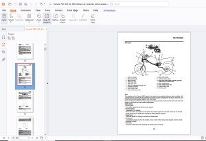
TABLE OF CONTENTS:
Yamaha FJR1300A(V) 2006 Service Manual - PDF DOWNLOAD
TABLE OF CONTENTS 0
GENERAL INFORMATION 9
IDENTIFICATION 10
FEATURES 11
IMPORTANT INFORMATION 39
CHECKING THE CONNECTIONS 41
SPECIAL TOOLS 42
SPECIFICATIONS 49
GENERAL SPECIFICATIONS 50
ENGINE SPECIFICATIONS 51
CHASSIS SPECIFICATIONS 58
ELECTRICAL SPECIFICATIONS 61
TIGHTENING TORQUES 64
LUBRICATION POINTS AND LUBRICANT TYPES 74
LUBRICATION SYSTEM CHART AND DIAGRAMS 78
COOLING SYSTEM DIAGRAMS 90
CABLE ROUTING 94
PERIODIC CHECKS AND ADJUSTMENTS115
PERIODIC MAINTENANCE118
ENGINE120
CHASSIS138
ELECTRICAL SYSTEM153
CHASSIS155
GENERAL CHASSIS158
FRONT WHEEL170
REAR WHEEL177
FRONT BRAKE182
REAR BRAKE194
ABS (ANTI-LOCK BRAKE SYSTEM)207
HANDLEBARS217
FRONT FORK222
STEERING HEAD232
REAR SHOCK ABSORBER ASSEMBLY236
SWINGARM240
SHAFT DRIVE244
ENGINE259
ENGINE REMOVAL262
CAMSHAFTS270
CYLINDER HEAD279
VALVES AND VALVE SPRINGS282
GENERATOR AND STARTER CLUTCH289
PICKUP ROTOR295
ELECTRIC STARTER298
CLUTCH302
SHIFT SHAFT317
OIL PUMP319
MIDDLE GEAR324
CRANKCASE335
CONNECTING RODS AND PISTONS343
CRANKSHAFT351
TRANSMISSION355
BALANCERS364
COOLING SYSTEM371
RADIATOR372
OIL COOLER375
THERMOSTAT377
WATER PUMP381
FUEL SYSTEM387
FUEL TANK388
THROTTLE BODIES391
AIR INDUCTION SYSTEM396
ELECTRICAL SYSTEM401
IGNITION SYSTEM404
ELECTRIC STARTING SYSTEM412
CHARGING SYSTEM420
LIGHTING SYSTEM424
SIGNALING SYSTEM430
COOLING SYSTEM440
FUEL INJECTION SYSTEM444
FUEL PUMP SYSTEM484
WINDSHIELD DRIVE SYSTEM490
ACCESSORY BOX SYSTEM496
IMMOBILIZER SYSTEM502
ABS (ANTI-LOCK BRAKE SYSTEM)514
ELECTRICAL COMPONENTS548
TROUBLESHOOTING575
TROUBLESHOOTING576
FJR1300A(V) 2006 WIRING DIAGRAM583
DESCRIPTION:
Yamaha FJR1300A(V) 2006 Service Manual - PDF DOWNLOAD
HOW TO USE THIS MANUAL :
This manual is intended as a handy, easy-to-read reference book for the mechanic. Comprehensive explanations of all installation, removal, disassembly, assembly, repair and inspection procedures are laid out with the individual steps in sequential order.1 The manual is divided into chapters. An abbreviation and symbol in the upper right corner of each page indicate the current chapter. Refer to “SYMBOLS” on the following page.2 Each chapter is divided into sections. The current section title is shown at the top of each page, except in Chapter 3 (“Periodic Inspections and Adjustments”), where the sub-section title (-s) appear. (In Chapter 3, “Periodic Inspections and Adjustments”, the sub-section title appears at the top of each page, instead of the section title.)3 Sub-section titles appear in smaller print than the section title.4 To help identify parts and clarify procedure steps, there are exploded diagrams at the start of each removal and disassembly section.5 Numbers are given in the order of the jobs in the exploded diagram. A circled number indicates a disassembly step.6 Symbols indicate parts to be lubricated or replaced (see “SYMBOLS”).7 A job instruction chart accompanies the exploded diagram, providing the order of jobs, names of parts, notes in jobs, etc.8 Jobs requiring more information (such as special tools and technical data) are described sequentially.
G.B 12/03/25
More products