$40
Yamaha YZFR6V(C) Service Manual - PDF DOWNLOAD
Yamaha YZFR6V(C) Service Manual - PDF DOWNLOAD
FILE DETAILS:
Yamaha YZFR6V(C) Service Manual - PDF DOWNLOAD
Language : English
Pages : 434
Downloadable : Yes
File Type : PDF
IMAGES PREVIEW OF THE MANUAL:
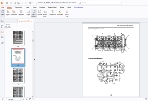
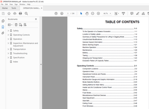
TABLE OF CONTENTS:
Yamaha YZFR6V(C) Service Manual - PDF DOWNLOAD
YZFR6V(C) Service Manual 1
Important Manual Information 3
How To Use This Manual 4
Symbols 5
Table Of Contents 7
General Information 9
Identification 10
Vehicle Identification Number 10
Model Label 10
Features 11
Outline Of The FI System 11
FI System 12
YCC-T (Yamaha Chip Controlled Throttle) 13
Mechanism Characteristics 13
Aims And Advantages Of Using YCC-T 13
YCC-T System Outline 14
YCC-T Control Outline 15
Instrument Functions 16
Tachometer 16
Clock Mode 16
Odometer, Tripmeter, And Stopwatch Modes 17
Stopwatch Mode 17
Coolant Temperature Display 17
Air Intake Temperature Display 18
Self-Diagnosis Device 18
Display Brightness And Shift Timing Indicator Light Control Mode 18
Important Information 20
Preparation For Removal And Disassembly 20
Replacement Parts 20
Gaskets, Oil Seals And O-Rings 20
Lock Washers/Plates And Cotter Pins 20
Bearings And Oil Seals 21
Circlips 21
Checking The Connections 22
Special Tools 23
Specifications 29
General Specifications 30
Engine Specifications 31
Engine 31
Fuel 31
Engine Oil 31
Oil Filter 31
Oil Pump 31
Cooling System 31
Spark Plug(s) 32
Cylinder Head 32
Camshaft 32
Timing Chain 33
Valve, Valve Seat, Valve Guide 33
Valve Spring 34
Cylinder 35
Piston 35
Piston Ring 35
Connecting Rod 36
Crankshaft 36
Clutch 36
Transmission 37
Shifting Mechanism 37
Air Filter 37
Fuel Pump 37
Injector 37
Throttle Body 37
Throttle Position Sensor 37
Fuel Injection Sensor 38
Idling Condition 38
Air Induction System 38
Chassis Specifications 39
Electrical Specifications 42
Tightening Torques 45
General Tightening Torque Specifications 45
Engine Tightening Torques 46
Connecting Rod Nut 48
Crankcase Bolt 48
Crankcase Stud Bolt 48
Cylinder Head Tightening Sequence: 49
Crankcase Tightening Sequence: 49
Chassis Tightening Torques 50
Front Wheel Axle Pinch Bolt 52
Lower Ring Nut 53
Lower Bracket Pinch Bolt 53
Lubrication Points And Lubricant Types 54
Engine 54
Chassis 56
Lubrication System Chart And Diagrams 58
Engine Oil Lubrication Chart 58
Lubrication Diagrams 60
Cooling System Diagrams 72
Cable Routing 76
Periodic Checks And Adjustments 91
Periodic Maintenance 94
Introduction 94
Periodic Maintenance Chart For The Emission Control System 94
General Maintenance And Lubrication Chart 94
Engine 97
Adjusting The Valve Clearance 97
Synchronizing The Throttle Bodies 99
Basic Procedure100
Alternate Procedure100
Adjusting The Throttle Cable Free Play101
Checking The Spark Plugs101
Measuring The Compression Pressure102
Checking The Engine Oil Level103
Changing The Engine Oil104
Measuring The Engine Oil Pressure105
Adjusting The Clutch Lever Free Play106
Replacing The Air Filter Element107
Checking The Throttle Body Joints108
Checking The Fuel Line108
Checking The Crankcase Breather Hose108
Checking The Exhaust System109
Checking The Canister (For California Only)109
Checking The Coolant Level111
Checking The Cooling System111
Changing The Coolant112
Chassis114
Adjusting The Front Disc Brake114
Adjusting The Rear Disc Brake114
Checking The Brake Fluid Level115
Checking The Front Brake Pads115
Checking The Rear Brake Pads115
Checking The Front Brake Hoses116
Checking The Rear Brake Hoses116
Adjusting The Rear Brake Light Switch116
Bleeding The Hydraulic Brake System117
Adjusting The Shift Pedal118
Adjusting The Drive Chain Slack118
Lubricating The Drive Chain119
Checking And Adjusting The Steering Head119
Checking The Front Fork121
Adjusting The Front Fork Legs121
Spring Preload121
Rebound Damping122
Compression Damping122
Adjusting The Rear Shock Absorber Assembly123
Spring Preload123
Rebound Damping124
Compression Damping124
Checking The Tires125
Checking The Wheels126
Checking And Lubricating The Cables127
Lubricating The Levers127
Lubricating The Pedals127
Lubricating The Sidestand127
Lubricating The Rear Suspension127
Electrical System128
Checking And Charging The Battery128
Checking The Fuses128
Replacing The Headlight Bulbs128
Adjusting The Headlight Beams128
Chassis131
General Chassis134
Front Wheel137
Removing The Front Wheel140
Checking The Front Wheel140
Disassembling The Front Wheel140
Assembling The Front Wheel141
Adjusting The Front Wheel Static Balance141
Checking The Front Brake Discs142
Installing The Front Wheel (Front Brake Discs)142
Rear Wheel144
Removing The Rear Wheel147
Disassembling The Rear Wheel147
Checking The Rear Wheel147
Checking The Rear Brake Caliper Bracket147
Checking The Rear Wheel Drive Hub147
Checking And Replacing The Rear Wheel Sprocket147
Assembling The Rear Wheel148
Adjusting The Rear Wheel Static Balance148
Checking The Rear Brake Disc148
Installing The Rear Wheel (Rear Brake Disc)148
Front Brake150
Introduction155
Checking The Front Brake Discs155
Replacing The Front Brake Pads156
Removing The Front Brake Calipers157
Disassembling The Front Brake Calipers157
Checking The Front Brake Calipers157
Assembling The Front Brake Calipers158
Installing The Front Brake Calipers158
Removing The Front Brake Master Cylinder159
Checking The Front Brake Master Cylinder159
Assembling The Front Brake Master Cylinder159
Installing The Front Brake Master Cylinder160
Rear Brake162
Introduction167
Checking The Rear Brake Disc167
Replacing The Rear Brake Pads167
Removing The Rear Brake Caliper168
Disassembling The Rear Brake Caliper168
Checking The Rear Brake Caliper169
Assembling The Rear Brake Caliper169
Installing The Rear Brake Caliper170
Removing The Rear Brake Master Cylinder171
Checking The Rear Brake Master Cylinder171
Assembling The Rear Brake Master Cylinder171
Installing The Rear Brake Master Cylinder171
Handlebars173
Removing The Handlebars175
Checking The Handlebars175
Installing The Handlebars175
Front Fork177
Removing The Front Fork Legs180
Disassembling The Front Fork Legs180
Checking The Front Fork Legs181
Assembling The Front Fork Legs182
Installing The Front Fork Legs186
Steering Head188
Removing The Lower Bracket191
Checking The Steering Head191
Installing The Steering Head191
Rear Shock Absorber Assembly193
Handling The Rear Shock Absorber195
Disposing Of A Rear Shock Absorber195
Removing The Rear Shock Absorber Assembly195
Checking The Rear Shock Absorber Assembly195
Checking The Connecting Arm And Relay Arm196
Installing The Relay Arm196
Installing The Rear Shock Absorber Assembly196
Swingarm198
Removing The Swingarm200
Checking The Swingarm200
Installing The Swingarm201
Chain Drive203
Removing The Drive Chain204
Checking The Drive Chain204
Checking The Drive Sprocket205
Checking The Rear Wheel Sprocket205
Checking The Rear Wheel Drive Hub205
Installing The Drive Chain205
Engine207
Engine Removal210
Installing The Engine215
Camshafts216
Removing The Camshafts218
Checking The Camshafts218
Checking The Timing Chain, Camshaft Sprockets, And Timing Chain Guides220
Checking The Timing Chain Tensioner220
Installing The Camshafts221
Cylinder Head224
Removing The Cylinder Head225
Checking The Cylinder Head225
Installing The Cylinder Head225
Valves And Valve Springs227
Removing The Valves228
Checking The Valves And Valve Guides228
Checking The Valve Seats230
Checking The Valve Springs232
Checking The Valve Lifters232
Installing The Valves233
Generator And Starter Clutch235
Removing The Generator237
Checking The Starter Clutch237
Installing The Starter Clutch237
Installing The Generator238
Pickup Rotor239
Removing The Pickup Rotor240
Installing The Pickup Rotor240
Electric Starter242
Checking The Starter Motor244
Assembling The Starter Motor245
Clutch246
Removing The Clutch250
Checking The Friction Plates250
Checking The Clutch Plates250
Checking The Clutch Springs251
Checking The Clutch Housing252
Checking The Clutch Boss252
Checking The Pressure Plate252
Checking The Primary Drive Gear252
Checking The Primary Driven Gear252
Checking The Pull Lever Shaft And Pull Rod252
Checking The Oil Pump Drive Sprocket And Oil Pump Drive Chain253
Installing The Clutch253
Shift Shaft256
Checking The Shift Shaft258
Checking The Stopper Lever258
Installing The Shift Shaft258
Oil Pump259
Removing The Oil Pan262
Checking The Oil Pump262
Checking The Relief Valve262
Checking The Oil Pipes263
Checking The Oil Strainer263
Assembling The Oil Pump263
Installing The Oil Pan263
Crankcase264
Disassembling The Crankcase266
Checking The Crankcase266
Checking The Oil Pipe266
Checking The Timing Chain266
Assembling The Crankcase266
Connecting Rods And Pistons268
Removing The Connecting Rods And Pistons269
Checking The Cylinders And Pistons269
Checking The Piston Rings270
Checking The Piston Pins271
Checking The Connecting Rods272
Installing The Connecting Rods And Pistons273
Crankshaft276
Removing The Crankshaft Journal Bearings277
Checking The Oil Nozzles277
Checking The Crankshaft And Connecting Rods277
Installing The Crankshaft279
Transmission280
Removing The Transmission285
Checking The Shift Forks285
Checking The Shift Drum Assembly285
Checking The Transmission286
Assembling The Main Axle And Drive Axle286
Installing The Transmission287
Cooling System289
Radiator290
Checking The Radiator292
Installing The Radiator292
Oil Cooler293
Checking The Oil Cooler295
Installing The Oil Cooler295
Thermostat296
Checking The Thermostat297
Installing The Thermostat297
Water Pump298
Checking The Water Pump299
Installing The Water Pump299
Fuel System301
Fuel Tank302
Removing The Fuel Tank304
Removing The Fuel Pump304
Checking The Fuel Pump Body304
Checking The Fuel Pump Operation304
Installing The Fuel Pump304
Installing The Fuel Tank305
Air Filter Case306
Removing The Fuel Hose (Primary Injector Fuel Rail To Secondary Injector Fuel Rail)308
Checking The Secondary Injectors308
Installing The Fuel Hose (Primary Injector Fuel Rail To Secondary Injector Fuel Rail)308
Throttle Bodies309
Checking The Primary Injectors313
Checking The Throttle Bodies313
Checking The Rollover Valve (For California Only)313
Checking The Fuel Pressure313
Adjusting The Throttle Position Sensor (For Throttle Valves)314
Adjusting The Throttle Position Sensor (For Throttle Cable Pulley)314
Installing The Throttle Body Joints315
Air Induction System316
Checking The Air Induction System320
Electrical System321
Ignition System324
Circuit Diagram324
Engine Stopping Due To Sidestand Operation326
Troubleshooting327
Electric Starting System330
Circuit Diagram330
Starting Circuit Cut-Off System Operation332
Troubleshooting334
Charging System336
Circuit Diagram336
Troubleshooting338
Lighting System340
Circuit Diagram340
Troubleshooting342
Signaling System344
Circuit Diagram344
Troubleshooting346
Cooling System352
Circuit Diagram352
Troubleshooting354
Fuel Injection System356
Circuit Diagram356
Ecu Self-diagnostic Function358
Engine Trouble Warning Light Indication And Fuel Injection System Operation358
Checking The Engine Trouble Warning Light358
Self-diagnostic Function Table359
Self-diagnostic Function Table359
Communication Error With The Meter361
Troubleshooting Method362
Diagnostic Mode363
Fault Code Table364
Sensor Operation Table367
Actuator Operation Table369
Troubleshooting Details371
Fuel Pump System396
Circuit Diagram396
Troubleshooting398
Electrical Components400
Checking The Switches404
Checking The Bulbs And Bulb Sockets407
Types Of Bulbs407
Checking The Condition Of The Bulbs407
Checking The Condition Of The Bulb Sockets408
Checking The Fuses408
Checking And Charging The Battery409
Checking The Relays412
Checking The Turn Signal Relay413
Checking The Relay Unit (Diode)414
Checking The Ignition Coils415
Checking The Crankshaft Position Sensor416
Checking The Lean Angle Sensor416
Checking The Starter Motor Operation416
Checking The Stator Coil417
Checking The Rectifier/Regulator417
Checking The Horn418
Checking The Oil Level Switch418
Checking The Fuel Sender418
Checking The Speed Sensor419
Checking The Radiator Fan Motors419
Checking The Coolant Temperature Sensor420
Checking The Throttle Position Sensor (For Throttle Valves)420
Checking The Throttle Position Sensor (For Throttle Cable Pulley)421
Checking The Fuel Pump421
Checking The Air Induction System Solenoid422
Checking The Atmospheric Pressure Sensor422
Checking The Cylinder Identification Sensor423
Checking The Intake Air Pressure Sensor423
Checking The Air Temperature Sensor423
Troubleshooting425
Troubleshooting426
General Information426
Starting Failures426
Engine426
Fuel System426
Electrical System426
Incorrect Engine Idling Speed426
Engine426
Fuel System426
Electrical System427
Poor Medium-and-High-Speed Performance427
Engine427
Fuel System427
Faulty Gear Shifting427
Shift Pedal Does Not Move427
Jumps Out Of Gear427
Faulty Clutch427
Overheating427
Overcooling428
Poor Braking Performance428
Faulty Front Fork Legs428
Unstable Handling428
Faulty Lighting Or Signaling System429
Wiring Diagram430
YZFR6V(C) 2006430
YZFR6V(C) 2006 Wiring Diagram433
YZFR6V(C) 2006 Wiring Diagram434
DESCRIPTION:
Yamaha YZFR6V(C) Service Manual - PDF DOWNLOAD
HOW TO USE THIS MANUAL:
This manual is intended as a handy, easy-to-read reference book for the mechanic. Comprehensive explanations of all installation, removal, disassembly, assembly, repair and check procedures are laid out with the individual steps in sequential order.1 The manual is divided into chapters. An abbreviation and symbol in the upper right corner of each page indicate the current chapter. Refer to “SYMBOLS”.2 Each chapter is divided into sections. The current section title is shown at the top of each page, except in Chapter 3 (“PERIODIC CHECKS AND ADJUSTMENTS”), where the sub-section title(s) appears. 3 Sub-section titles appear in smaller print than the section title.4 To help identify parts and clarify procedure steps, there are exploded diagrams at the start of each removal and disassembly section.5 Numbers are given in the order of the jobs in the exploded diagram. A circled number indicates a disassembly step.6 Symbols indicate parts to be lubricated or replaced. Refer to “SYMBOLS”.7 A job instruction chart accompanies the exploded diagram, providing the order of jobs, names of parts, notes in jobs, etc. 8 Jobs requiring more information (such as special tools and technical data) are described sequentially.
G.B 13/03/25
More products