$35
Yanmar TNE-Series Engines Service Manual 915185 – PDF DOWNLOAD
Yanmar TNE-Series Engines Service Manual 915185 – PDF DOWNLOAD
FILE DETAILS:
Yanmar TNE-Series Engines Service Manual 915185 – PDF DOWNLOAD
Language : English
Pages : 136
Downloadable : Yes
File Type : PDF
Size: 4.01 MB
IMAGES PREVIEW OF THE MANUAL:
DESCRIPTION:
Yanmar TNE-Series Engines Service Manual 915185 – PDF DOWNLOAD
FOREWORD:
This Service Manual describes the procedure of maintenance and service of the Yanmar industrial
TNE series engine (Special swirl precombustion chamber (hereinafter “Indirect injection system”)
and Direct injection systems).
- Before starting service and maintenance of TNE engine, you are requested to read this Service
Manual carefully to your full understanding and to take careful note that the standard TNE engine
may differ in the structure and applicable specification from that loaded on each of individual driven
machines (such as the generator, pump, compressor, and combine, etc. ). - For further information, carefully read the Service Manual issued for each driven machine. _
This Service Manual in subject to changes, with or without notice, with respect to the structure and
the content of maintenance for the purpose of improving engine quality.
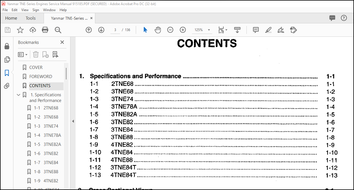
TABLE OF CONTENTS:
Yanmar TNE-Series Engines Service Manual 915185 – PDF DOWNLOAD
COVER……………………………………………………………………………………….. 1
FOREWORD…………………………………………………………………………………….. 2
CONTENTS…………………………………………………………………………………….. 3
1. Specifications and Performance……………………………………………………………… 7
1-1 2TNE68……………………………………………………………………………… 7
1-2 3TNE68……………………………………………………………………………… 8
1-3 3TNE74……………………………………………………………………………… 9
1-4 3TNE78A…………………………………………………………………………….. 10
1-5 3TNE82A…………………………………………………………………………….. 11
1-6 3TNE82……………………………………………………………………………… 12
1-7 3TNE84……………………………………………………………………………… 13
1-8 3TNE88……………………………………………………………………………… 14
1-9 4TNE82……………………………………………………………………………… 15
1-10 4TNE84……………………………………………………………………………… 16
1-11 4TNE88……………………………………………………………………………… 17
1-12 3TNE84T…………………………………………………………………………….. 18
1-13 4TNE84T…………………………………………………………………………….. 19
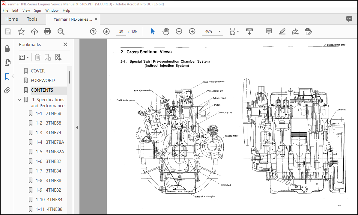
2. Cross Sectional Views……………………………………………………………………… 20
2-1 Special Swirl Pre-combustion Chamber System…………………………………………….. 20
2-2 Direct Injection System………………………………………………………………. 21
3. Cooling Water,Lubricating Oil and Fuel Oil…………………………………………………… 22
3-1 Cooling water……………………………………………………………………….. 22
3-2 Lubricating oil……………………………………………………………………… 22
3-3 Fuel oil……………………………………………………………………………. 24
4. Troubleshooting…………………………………………………………………………… 25
4-1 Trouble causes and remedies…………………………………………………………… 25
4-2 Trouble diagnousis through measurement of compression pressure……………………………. 27
5. Special Service Tools and Measuring Instruments………………………………………………. 28
5-1 Special service tools………………………………………………………………… 28
5-2 Measuring instruments………………………………………………………………… 30
6. Measurement,Inspection and Adjustment……………………………………………………….. 33
6-1 Measuring the compression pressure…………………………………………………….. 33
6-2 Adjusting the valve head clearance…………………………………………………….. 35
6-3 Checking the V-belt tension…………………………………………………………… 36
6-4 Measuring and checking the injection pressure and spray patterns of the fuel injection valve…. 36
6-5 Checking and adjusting the fuel injection timing………………………………………… 40
6-6 Adjusting the no-load maximum(or minimum)revolutions…………………………………….. 42
6-7 Checking the cooling water system and radiator for water leakage………………………….. 42
6-8 Checking the battery…………………………………………………………………. 43
6-9 Checking sensors…………………………………………………………………….. 45
6-10 Checking the oil cooler………………………………………………………………. 46
6-11 Checking the piston cooling nozzle…………………………………………………….. 47
7. Measuring Procedures,Service Data and Corrective Action……………………………………….. 48
7-1 Cylinder head……………………………………………………………………….. 48
7-2 Cylinder block………………………………………………………………………. 54
7-3 Valve rocker arm…………………………………………………………………….. 57
7-4 Piston and piston ring……………………………………………………………….. 59
7-5 Connecting rod………………………………………………………………………. 64
7-6 Camshaft……………………………………………………………………………. 67
7-7 Crankshaft………………………………………………………………………….. 69
7-8 Gears………………………………………………………………………………. 72
7-9 Trochoid pump……………………………………………………………………….. 74
8. Disassembly and Reassembly…………………………………………………………………. 75
8-1 Disassembly…………………………………………………………………………. 75
8-2 Precautions before and during reassembly……………………………………………….. 80
9. Service Data……………………………………………………………………………… 84
9-1 Cylinder head……………………………………………………………………….. 84
9-2 Cylinder block………………………………………………………………………. 85
9-3 Valve rocker arm…………………………………………………………………….. 85
9-4 Piston……………………………………………………………………………… 86
9-5 Piston ring…………………………………………………………………………. 87
9-6 Connecting rod………………………………………………………………………. 88
9-7 Camshaft……………………………………………………………………………. 88
9-8 Crankshaft………………………………………………………………………….. 88
9-9 Side gap and backlash………………………………………………………………… 89
9-10 Others……………………………………………………………………………… 89
10. Tightening Torque…………………………………………………………………………. 90
10-1 Main bolt/nut……………………………………………………………………….. 90
10-2 Standard bolt and nut………………………………………………………………… 90
11. Fuel Injection Pump for Indirect Injection System…………………………………………….. 91
11-1 Exploded views(YPFR type)…………………………………………………………….. 91
11-2 Disassembly…………………………………………………………………………. 92
11-3 Inspection………………………………………………………………………….. 93
11-4 Reassembly………………………………………………………………………….. 95
12. Fuel Injection Pump for Direct Injection System………………………………………………. 96
12-1 Exploded Views(YPES type)…………………………………………………………….. 96
12-2 Special service tools for disassembly and reassembly…………………………………….. 97
12-3 Disassembly…………………………………………………………………………. 98
12-4 Inspection…………………………………………………………………………..102
12-5 Reassembly…………………………………………………………………………..104
13. Governor………………………………………………………………………………….109
13-1 Exploded views of governor for indirect injection system………………………………….109
13-2 Exploded views of governor for direct injection system……………………………………110
13-3 Disassembly………………………………………………………………………….111
13-4 Inspection…………………………………………………………………………..115
13-5 Reassembly…………………………………………………………………………..117
14. Turbocharger………………………………………………………………………………121
14-1 Specifications……………………………………………………………………….121
14-2 Construction…………………………………………………………………………121
14-3 Waste gate valve adjusting method………………………………………………………123
14-4 Exploded view of Turbocharger(w/waste gate)……………………………………………..125
14-5 Tightening torque…………………………………………………………………….126
14-6 Service standards…………………………………………………………………….126
15. Service information for CARB ULG regulation…………………………………………………..127
15-1 Emission control labels……………………………………………………………….127
15-2 Limiting the high idle and low idle adjustment screw……………………………………..132
15-3 Limiting the fuel volume limiter screw………………………………………………….133
Attached Drawing 1. Exploded Views of Engine Components……………………………………………134
Attached Drawing 2. Exploded Views of Engine Components……………………………………………135
More products